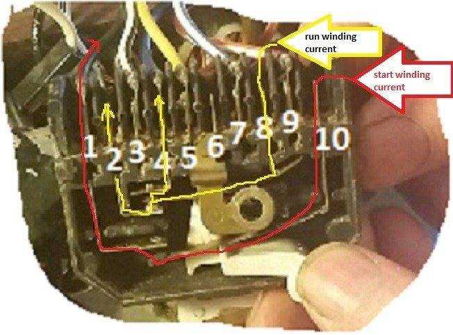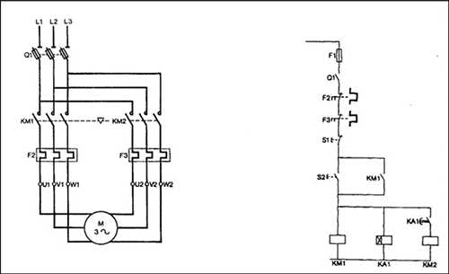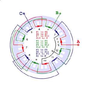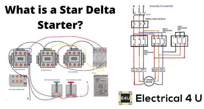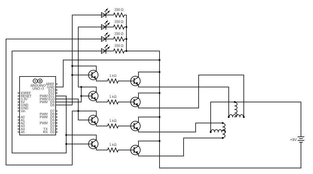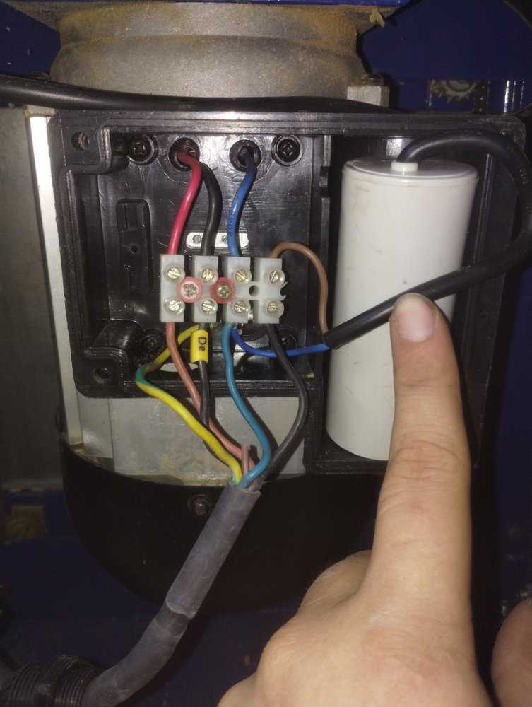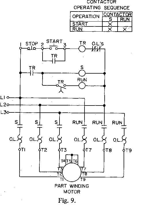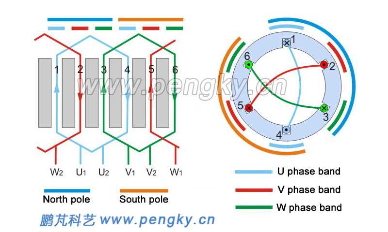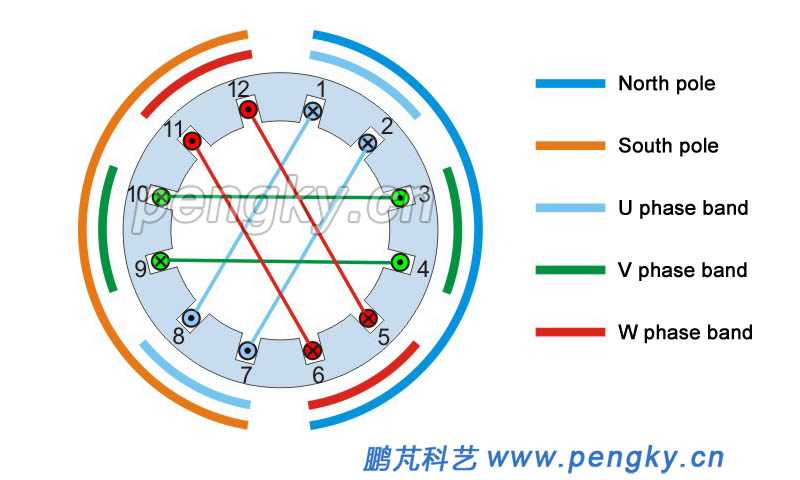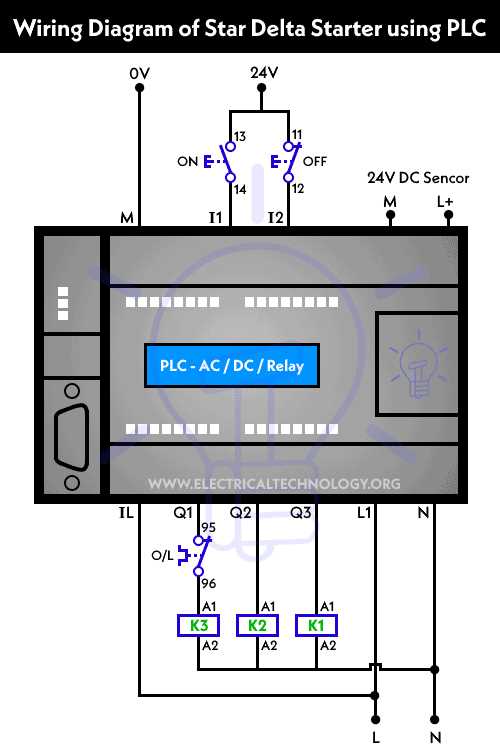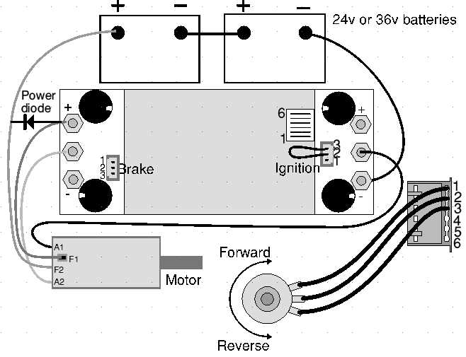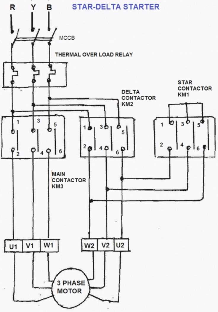
part winding motor wiring diagram

When working with intricate electrical setups, it’s essential to comprehend the underlying structure of different connection methods. This knowledge helps ensure reliable performance and prevents potential issues that can arise from improper configurations. In this section, we’ll explore one such method, breaking down its core principles and applications in modern systems.

The focus will be on a particular type of configuration that is commonly used in industrial and mechanical settings. This approach divides tasks between various internal components, allowing for efficient control and energy distribution. By understanding the layout and purpose behind each element, you’ll gain insights into how this technique optimizes performance in various machines.

We will also touch on the key aspects of configuring these setups for different use cases, highlighting common challenges and solutions. By the end of this guide, you’ll have a clear grasp of how these connections operate, along

Overview of Part Winding Motor Configuration
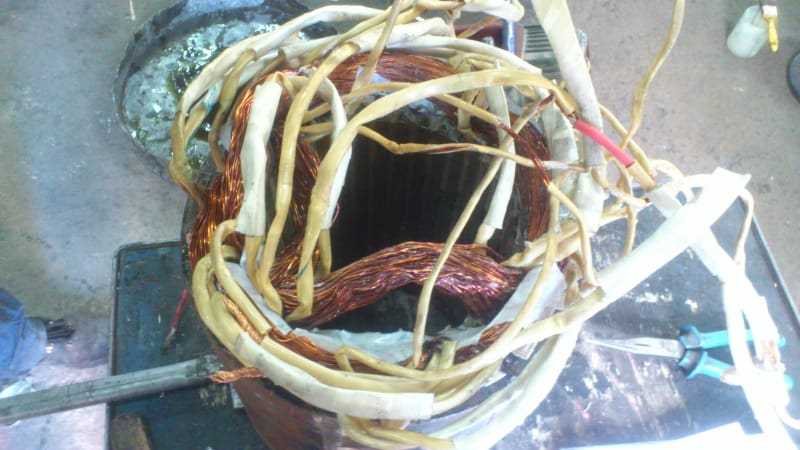
part winding motor wiring diagram

This setup involves a specialized approach to managing electrical machinery, allowing for varying operational phases depending on the required output. It utilizes a strategy that optimizes energy usage and helps ensure efficient performance during initial startup and full operation. The arrangement typically involves two stages, making it adaptable to different power demands.

Key Benefits: The main advantage of this configuration is its ability to balance energy distribution. By dividing the activation into separate sections, it reduces the initial load on the electrical system, leading to more controlled and smoother operation.

Usage Scenarios: This method is often implemented in systems where gradual engagement of power is crucial. It helps extend equipment life and reduces mechanical stress during operation. Applications range from large industrial machines to specialized automated equipment.

Key Features of Part Winding Motors

This section outlines the essential characteristics of machines designed for progressive control over their operational phases. These machines are often used where smooth transitions are needed between various levels of performance. Their unique construction allows for more efficient handling of tasks, ensuring that they operate effectively while maintaining balance and precision.

Operational Flexibility
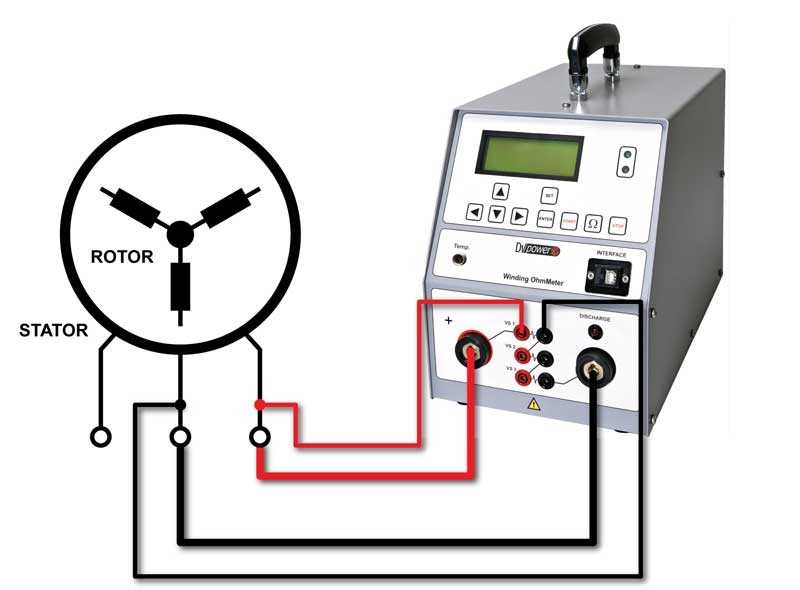
part winding motor wiring diagram

These machines are equipped to adjust their workload depending on the demands placed upon them. This flexibility is particularly useful in environments where fluctuating needs must be met without compromising on efficiency. By switching between modes, they can handle both low and high-power requirements with ease.

Energy Efficiency
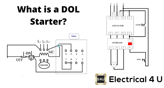
part winding motor wiring diagram

One of the most important aspects of these devices is their ability to minimize energy consumption during initial stages of operation. This feature is critical for reducing operational costs, as it allows the machine to begin functioning at lower power levels, gradually increasing output as necessary.

Feature Benefit
Phase Adjustment Understanding the Role of Windings

In electric systems, certain internal components are key to generating the necessary force for operation. These elements are organized in a way that allows for smooth and controlled energy transfer. Their structure and arrangement directly impact how efficiently the device functions under varying conditions.

Energy Flow and Control

The internal components are responsible for controlling the direction and amount of current that passes through the system. By adjusting their configuration, it becomes possible to manage different levels of energy, ensuring a smooth start or increased performance when needed. This control helps in optimizing overall efficiency and longevity.

Efficiency and Performance Optimization

part winding motor wiring diagram

Another important function of these internal structures is to help balance the workload. When designed effectively, they distribute energy in a way that reduces strain on individual parts. This improves durability and contributes to a stable and efficient operation across various stages of performance.

Benefits of Using Part Winding Systems

part winding motor wiring diagram

Employing systems that gradually increase the operational capacity can offer significant advantages in various applications. These systems enable smooth transitions from low to full performance, which helps reduce stress on equipment and improves overall longevity. By optimizing the flow of electrical energy, this approach ensures that systems operate efficiently while minimizing wear and tear.

Enhanced Equipment Lifespan

part winding motor wiring diagram

One key advantage is the extension of equipment life. Gradual start-up methods reduce the initial load, leading to fewer mechanical and electrical stresses. This, in turn, helps in preserving the integrity of the components, allowing machinery to function effectively over an extended period.

Energy Efficiency and Cost Reduction

part winding motor wiring diagram

Another benefit is the improved energy efficiency. Systems designed to optimize performance in stages consume less power during the initial phases, helping to lower overall energy consumption. This not only contributes to reduced operational costs but also aligns with modern energy-saving practices.

Step-by-Step Motor Wiring Instructions

part winding motor wiring diagram

The following instructions will guide you through the connection process for a multi-phase electric unit. It’s crucial to ensure all components are correctly linked to avoid potential issues in operation. This method provides a structured approach to help you successfully configure your equipment.

Preparation Before Starting

part winding motor wiring diagram

Before beginning, gather all necessary tools and materials. Verify that the power source is off and all components are properly identified. Carefully review the labels or markings on the device, as they will assist in the correct setup.

Connection Process

Follow the steps outlined below to connect your equipment safely and efficiently. Ensure that you double-check each step to avoid misconfiguration.

Step Description
1

Common Wiring Schemes for Efficiency

When it comes to optimizing energy usage in electromechanical systems, selecting the right connection configurations is crucial. These setups not only enhance performance but also contribute to overall system longevity. By adopting specific techniques, users can significantly reduce power consumption and improve operational efficiency.

One effective approach is the use of series connections, which enables the division of electrical loads across multiple components. This method minimizes current levels, reducing heat generation and wear on parts. Another technique is the implementation of parallel arrangements, which allows for consistent voltage supply while facilitating redundancy. This ensures that if one pathway fails, others can continue to operate, enhancing reliability.

Furthermore, employing star and delta configurations is beneficial in applications requiring variable speed control. These layouts provide flexibility in torque and speed management, leading to better adaptability in various operational conditions. By understanding and utilizing these common setups, users can achieve greater efficiency and maintain optimal performance in their systems.

How to Identify Motor Winding Phases

Understanding the phases of a rotating device is crucial for efficient operation and maintenance. Correctly identifying each phase ensures optimal performance and prevents potential issues during setup or troubleshooting. This process can help in determining the appropriate connections and configurations needed for various applications.

Step 1: Start by locating the terminals that correspond to each section of the coil assembly. These terminals are typically labeled, but if not, careful observation can reveal their placement based on the manufacturer’s design.

Step 2: Utilize a multimeter to measure resistance between the terminals. This method allows for distinguishing between different sections, as the resistance values will indicate which parts are electrically connected. Compare the readings to establish relationships among the terminals.

Step 3: Next, trace the connections back to the power source or control system. This step involves checking the continuity to ensure that each phase is properly linked and functioning as intended. It’s essential to verify that no shorts or miswirings exist.

Step 4: Lastly, consult the technical documentation provided by the manufacturer for specific guidance on identifying the phases. This information can offer invaluable insights, especially when dealing with complex configurations or unique designs.

Safety Considerations When Wiring Motors

part winding motor wiring diagram

Ensuring safety during the connection of electrical devices is crucial to prevent accidents and damage. Understanding the proper techniques and precautions can significantly reduce risks associated with electrical installations. It is essential to be aware of the potential hazards and implement strategies to maintain a safe working environment.

Understanding Electrical Hazards

part winding motor wiring diagram

When engaging with electrical installations, individuals must recognize various hazards, including electric shock and short circuits. Always consider the voltage levels and the current capacity of the components involved. Proper insulation and using the correct protective equipment are vital in safeguarding oneself and others during the installation process.

Best Practices for Safe Connections

To minimize risks, ensure that all components are rated for the intended application. Double-check that power sources are disconnected before starting any installation. Additionally, keeping work areas organized and free of clutter can help prevent accidents. Regularly inspecting tools and equipment for wear can also enhance safety during the setup.

Best Practices for Wiring Connections

Ensuring optimal performance and reliability in electrical systems requires careful attention to how components are linked. Following established guidelines not only enhances functionality but also minimizes the risk of faults and failures.

  • Choose Quality Materials: Use high-grade conductors and insulation to withstand operational conditions.
  • Maintain Proper Insulation: Ensure that all connections are well-insulated to prevent short circuits and electrical shocks.
  • Secure Connections: Utilize reliable connectors and terminals that provide a firm grip, reducing the likelihood of disconnections.
  • Follow Manufacturer Guidelines: Adhere to specifications provided by manufacturers for optimal setup and compatibility.
  • Minimize Length: Keep leads as short as feasible to reduce resistance and potential signal loss.

Implementing these strategies will greatly enhance the safety and efficiency of electrical setups, contributing to their longevity and effectiveness.

Tips for Troubleshooting Wiring Diagrams

Troubleshooting electrical schematics can be challenging, yet understanding a few key strategies can greatly enhance the process. By following systematic approaches, one can identify and resolve issues more efficiently, ensuring the smooth operation of electrical systems.

1. Review the Basics: Begin by familiarizing yourself with the fundamental principles of electricity and the specific features of the system in question. Understanding voltage, current, and resistance will help in diagnosing problems effectively.

2. Check Connections: Loose or corroded connections are common culprits in electrical failures. Inspect all terminals and junctions, ensuring they are secure and free from debris or oxidation. This simple step can often resolve many issues.

3. Use Multimeters: A multimeter is an invaluable tool for troubleshooting. It allows you to measure voltage, current, and resistance at various points in the circuit, helping to pinpoint the location of a fault.

4. Consult Manufacturer Resources: Manufacturer documentation often contains valuable information about common problems and their solutions. Referencing these resources can save time and provide insights that may not be immediately obvious.

5. Take Systematic Notes: Keeping detailed records of your troubleshooting process can help you track what has been checked and what remains. This organized approach can prevent redundant efforts and lead to quicker resolutions.

6. Test Components Individually: If a specific part is suspected to be faulty, isolate it from the system and test it independently. This method can help determine if the issue lies within that component or elsewhere in the system.

7. Seek Expert Advice: If troubleshooting becomes overwhelming, don’t hesitate to consult with a knowledgeable technician or technician. Their experience can provide new perspectives and solutions that may not have been considered.

Tools Needed for Motor Wiring Setup

part winding motor wiring diagram

Setting up electrical connections requires a specific set of instruments to ensure a smooth and efficient process. Having the right tools not only simplifies the task but also enhances safety and accuracy. Below are essential implements that should be part of your toolkit.

Essential Instruments

part winding motor wiring diagram

  • Wire Strippers: Useful for removing insulation from electrical conductors without damaging the wire.
  • Screwdrivers: A variety of types and sizes, including flat-head and Phillips, are necessary for securing connections.
  • Multimeter: An essential device for measuring voltage, current, and resistance, helping to troubleshoot any issues.
  • Crimping Tool: Ideal for joining two pieces of metal by deforming one or both of them to hold the other.
  • Electrical Tape: Used for insulating wires and making safe, secure connections.

Safety Equipment

part winding motor wiring diagram

  • Safety Glasses: Protect your eyes from debris or sparks during the setup process.
  • Gloves: Insulated gloves help prevent electrical shock while handling live wires.
  • First Aid Kit: Always have a kit on hand in case of any accidents or injuries.

Equipped with these tools, you can proceed with confidence, ensuring both safety and effectiveness in your electrical setup tasks.

Understanding Electrical Load and Power Flow

Electrical load and power flow are fundamental concepts that govern how energy is transferred and utilized within various systems. By examining these elements, one can gain insights into the efficiency and performance of electrical devices and systems. A clear understanding of how energy is consumed and the characteristics of the load can significantly impact operational effectiveness.

Electrical load refers to the amount of power required by a device or system to function properly. It can vary depending on the operational conditions and the nature of the connected equipment. Different types of loads, such as resistive, inductive, and capacitive, interact with the energy supply in distinct ways, influencing overall performance and efficiency.

Power flow describes the movement of electrical energy through a circuit or system. It involves the transfer of energy from the source to the load, encompassing factors like voltage, current, and impedance. Understanding power flow is essential for optimizing system performance and ensuring that all components operate within their designated parameters.

By analyzing both electrical load and power flow, one can identify potential inefficiencies, prevent overload conditions, and enhance the overall reliability of the electrical setup. This knowledge is crucial for anyone involved in the design, maintenance, or operation of electrical systems, as it enables informed decisions that lead to improved performance and longevity.