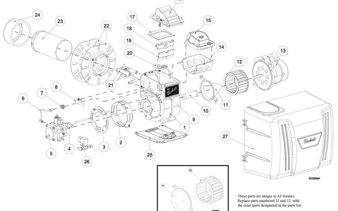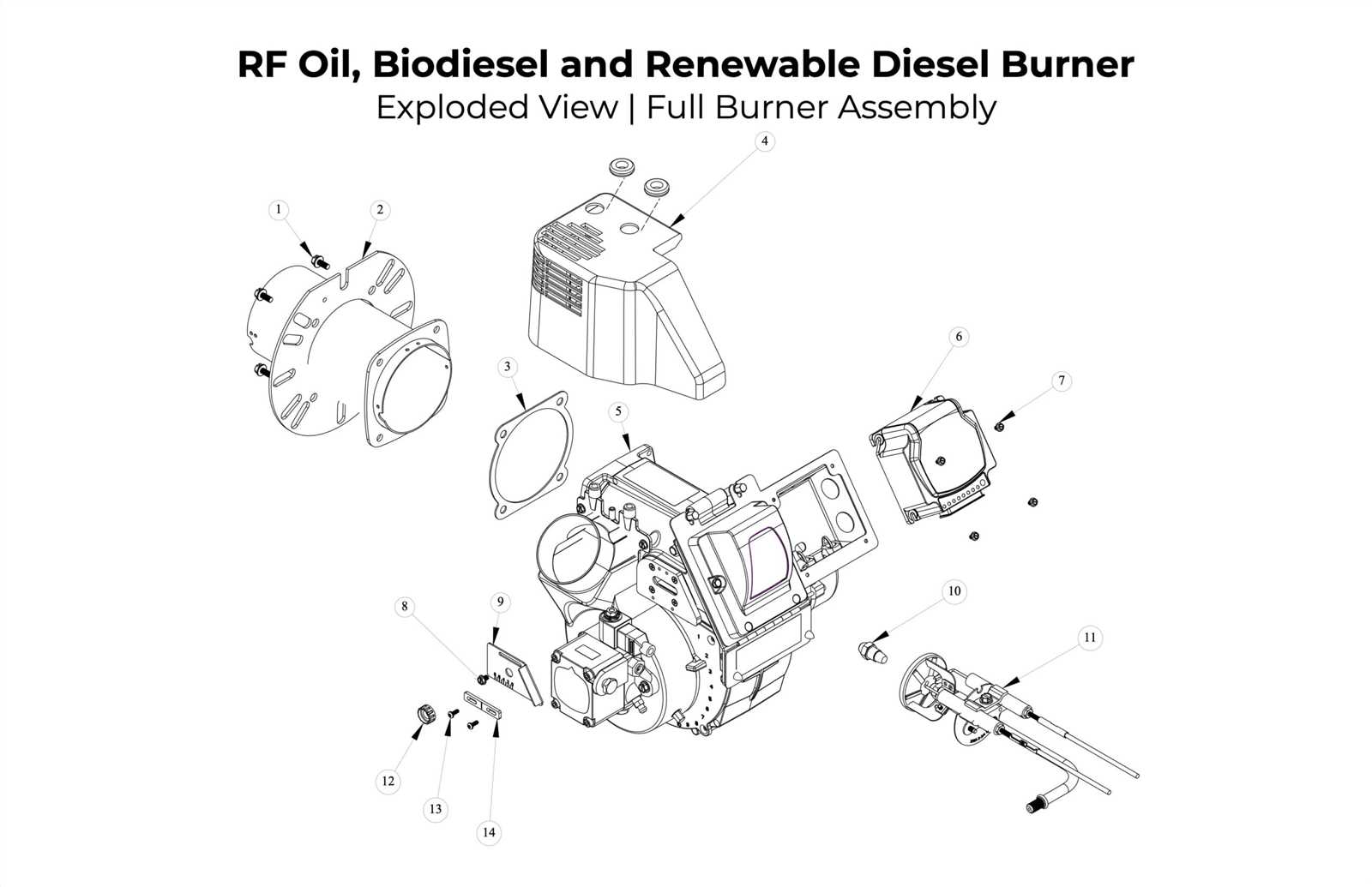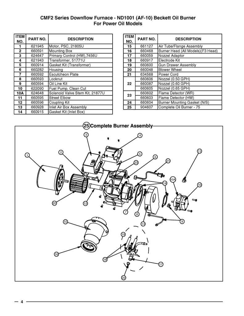
In the realm of home heating systems, understanding the intricate elements that compose the operational core can unveil a world of functionality and precision. Each component plays a crucial role in the seamless operation of the heating apparatus, ensuring optimal performance and efficiency.
Delving deeper into the inner workings reveals a network of interconnected parts, each tailored to perform specific tasks that collectively contribute to the system’s overall functionality. These components, meticulously designed and engineered, uphold the integrity and reliability essential for sustained performance.
Unveiling the inner mechanisms sheds light on the sophisticated synergy between parts, illustrating how each piece interacts harmoniously to achieve the desired outcome. This exploration not only enhances understanding but also underscores the importance of each element in the grand scheme of heating efficiency.
In this section, we will explore the key elements that make up a typical combustion heating device. Understanding how each piece functions can help in maintaining, troubleshooting, and enhancing the system’s efficiency. We’ll break down each part, explaining its role in the overall mechanism.
- Combustion Chamber: The area where fuel is ignited to produce heat. Proper operation of this section is crucial for energy efficiency and safe use.
- Fuel Pump: Responsible for transferring fuel into the system
Essential Parts of the Oil Burner
The operation of combustion devices relies on a collection of interconnected components, each playing a critical role in ensuring efficient fuel conversion and maintaining safe performance. Understanding these components allows for better maintenance and troubleshooting.
- Fuel Pump: Responsible for drawing and delivering the fuel to the combustion chamber at the required pressure for proper atomization.
- Ignition Transformer: Generates the high voltage needed to create a spark, igniting the air-fuel mixture within the system.
- Nozzle: Sprays fuel into fine particles, ensuring optimal combustion when mixed with air.
- Electrodes: Positioned near the nozzle, these create the spark needed to ignite the fuel-air mixture.
- Air Intake: Controls the amount of air entering the system, ensuring a balanced fuel-to-air ratio for efficient
Functionality of Each Component Explained
Understanding the operation of each element within a combustion system is crucial for effective maintenance and troubleshooting. Each component plays a vital role in ensuring optimal performance and efficiency. Below, we explore the specific functions of these essential elements.
Fuel Pump: This unit is responsible for drawing fuel from the storage tank and delivering it to the combustion chamber at a regulated pressure. Its efficiency directly impacts the system’s overall performance.
Ignition Transformer: This device generates the high-voltage spark necessary to ignite the fuel-air mixture. Its reliability is key to achieving a consistent flame and preventing unburned fuel accumulation.
Air Fan: The air fan supplies the required amount of air to support combustion. Proper airflow is essential for efficient burning and minimizes emissions, ensuring compliance with environmental standards.
Electrode Assembly: Positioned within the combustion chamber, this assembly creates the spark that initiates combustion. Its alignment and condition are critical for achieving a stable flame.
Control Module: This component regulates the entire operation by monitoring parameters such as temperature and pressure. It ensures that the system responds appropriately to varying demands, enhancing safety and efficiency.
Flame Sensor: The flame sensor detects the presence of a flame during operation. It plays a vital role in safety by shutting down the system if a flame is not detected, preventing potential hazards.
Combustion Chamber: This is where the actual burning of fuel occurs. Its design influences heat transfer and efficiency, making it a critical component for effective energy generation.
By understanding the functionality of each element, users can ensure that their systems operate smoothly and efficiently, minimizing downtime and maximizing performance.
Visual Representation of Oil Burner Diagram
This section aims to provide a clear and informative illustration of the components involved in combustion systems. Understanding these elements is crucial for proper maintenance and troubleshooting. Visual aids can enhance comprehension, making it easier for technicians and users alike to navigate the complexities of these devices.
Key Components Overview
- Fuel Supply System
- Ignition Mechanism
- Air Intake
- Control Unit
- Combustion Chamber
Each of these components plays a vital role in the overall functionality, and their arrangement can significantly impact performance. A well-organized visual representation can illustrate how these parts interact within the system.
Benefits of Visual Aids
- Enhances understanding of complex structures.
- Facilitates easier troubleshooting and repairs.
- Supports training and educational efforts.
- Encourages proper maintenance practices.
Utilizing diagrams can ultimately lead to more efficient operation and extended lifespan of the equipment, benefiting both users and technicians in their daily tasks.
Common Issues and Solutions
In any heating system, various complications can arise that affect efficiency and performance. Understanding these common challenges allows for timely interventions and maintenance, ensuring optimal functionality.
Fuel Delivery Problems
One frequent issue is inadequate fuel flow, often caused by clogged filters or faulty pumps. Regular inspection and replacement of filters can mitigate this, while ensuring the pump is functioning correctly will restore proper operation.
Ignition Failures
Another challenge is ignition malfunction, which may stem from dirty electrodes or improper settings. Cleaning the ignition components and checking alignment can resolve these issues, leading to reliable starts.
Maintenance Tips for Optimal Performance
Ensuring the longevity and efficiency of your heating system requires regular upkeep. By following these practical suggestions, you can enhance functionality and prevent potential issues.
- Regularly inspect components for wear and tear.
- Clean filters and vents to improve airflow.
- Check for leaks and seal any gaps promptly.
- Maintain proper fuel levels to avoid disruptions.
Additionally, consider scheduling professional evaluations at least once a year to ensure everything operates smoothly.
Safety Features in Oil Burners
Ensuring the protection of users and the environment is a paramount concern in heating systems. Various mechanisms and technologies are integrated into these systems to minimize risks and enhance safety during operation. Understanding these features is essential for both operators and technicians, as they play a critical role in maintaining safe conditions.
Automatic Shutoff Mechanisms
One of the primary safety components is the automatic shutoff mechanism. This feature activates when irregularities are detected, such as pressure drops or flame failure. By immediately stopping fuel flow, it prevents potential hazards, ensuring that the system operates within safe parameters.
Flame Monitoring Systems
Another vital aspect is the flame monitoring system. This technology continuously observes the combustion process, providing real-time feedback. If a flame goes out or becomes unstable, the system triggers an alert or shuts down the operation, safeguarding against dangerous situations.
Incorporating these safety features significantly reduces the risk of accidents and enhances the overall reliability of heating systems. Regular maintenance and inspections are also crucial to ensure these mechanisms function correctly, providing peace of mind to users.
Replacement Parts and Their Importance
Ensuring the longevity and efficiency of heating systems relies heavily on the availability and quality of components. When key elements wear out or fail, timely replacements are essential to maintain optimal performance and prevent costly breakdowns.
Impact on Efficiency
Substituting worn components can significantly enhance the overall functioning of the system. New elements not only restore lost efficiency but can also improve energy consumption, leading to reduced operating costs.
Safety Considerations
Utilizing high-quality replacements is crucial for safety. Faulty or degraded components can pose risks, including fire hazards or harmful emissions. Regular checks and prompt replacements help ensure a safe operating environment.
How to Read the Parts Diagram
Understanding a schematic can significantly enhance your ability to maintain and troubleshoot heating equipment. It serves as a visual guide, providing insights into the configuration and functionality of each component, allowing for easier identification and resolution of issues.
Identifying Components

Begin by familiarizing yourself with the labels and symbols used in the illustration. Each part is typically represented with unique identifiers that correspond to specific functions within the system, making it easier to locate and assess individual elements.
Following the Flow

Next, trace the connections between the various components. Observing the flow of energy or materials can help you understand how the system operates as a whole, enabling more effective troubleshooting and repairs.
Comparing Beckett Models and Specifications
This section aims to provide a comprehensive overview of various models and their unique specifications, highlighting the distinctions and similarities that can influence selection for different applications. Understanding these differences is crucial for making informed decisions tailored to specific needs.
Model Variations: Each variant presents unique characteristics, such as efficiency ratings, fuel consumption, and operational capacities. These factors play a significant role in determining the best fit for specific environments, whether residential or commercial.
Technical Specifications: Key metrics, including burner capacity, ignition types, and safety features, are essential for evaluating performance. Specifications may also encompass environmental considerations, such as emissions standards and energy efficiency, which are increasingly important in today’s market.
In conclusion, comparing the various models allows for a clearer understanding of their functionalities, guiding users toward choices that enhance performance and reliability in their heating systems.
FAQs About Oil Burner Parts
This section addresses common inquiries regarding components related to heating systems. Understanding these elements can enhance efficiency and longevity, ensuring optimal functionality.
Question Answer What are the main components? Key elements include the pump, nozzle, and combustion chamber, each playing a vital role in performance. How often should I replace these components? Regular inspections are recommended, with replacements typically needed every 1-3 years depending on usage. What are signs of wear? Common indicators include unusual noises, poor heating efficiency, and frequent cycling on and off. Can I fix issues myself? Minor adjustments may be manageable, but professional assistance is advised for complex problems to ensure safety.