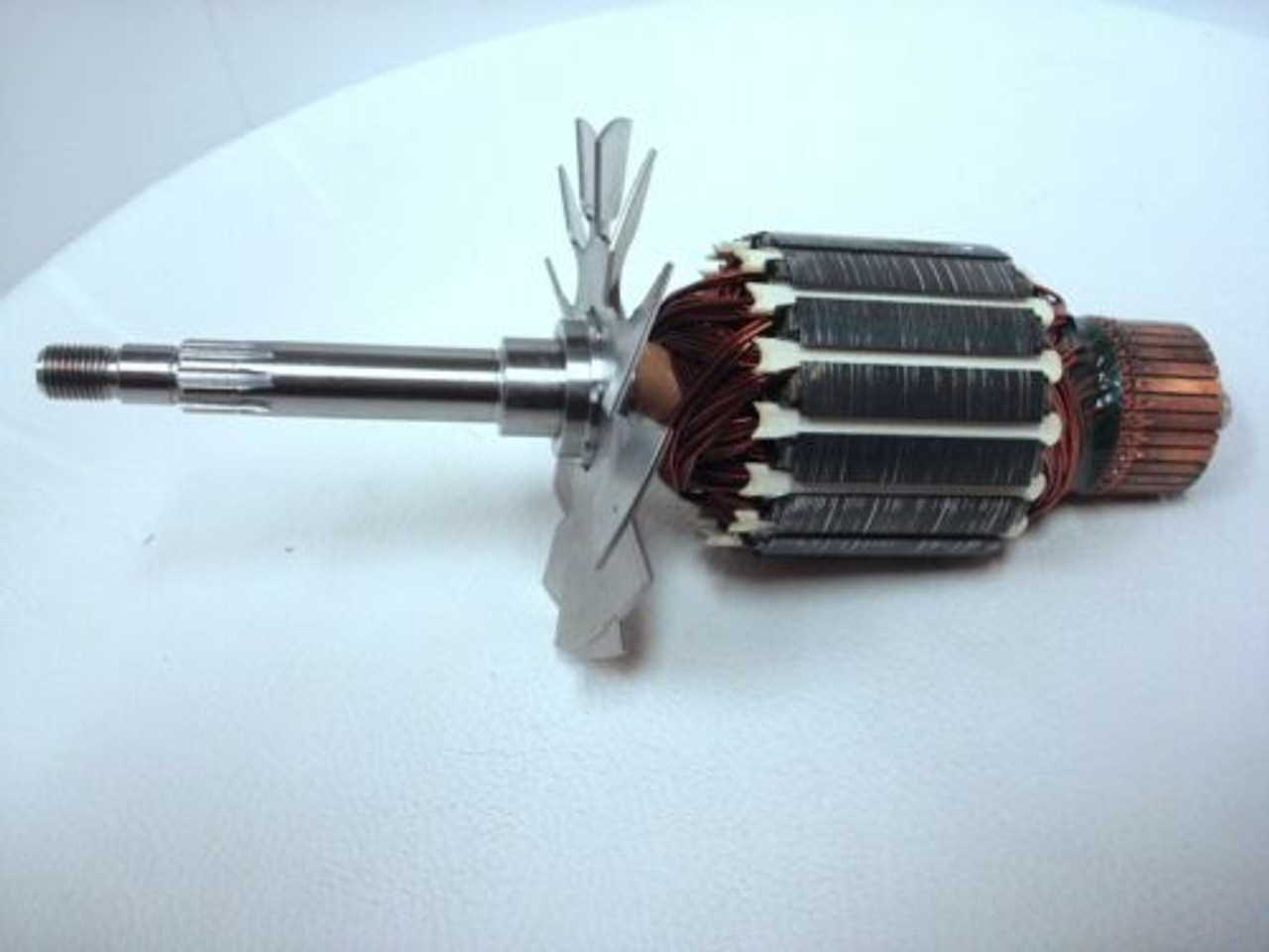
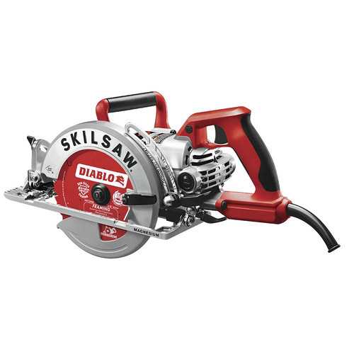
Blade Bolt: A fastener that holds the blade securely in place, making it easy to remove and replace when needed
Handle Structure and Design
The handle plays a crucial role in ensuring user comfort and precise control. Its design incorporates ergonomic considerations to facilitate ease of use, even during extended periods of operation. A well-crafted handle provides a secure grip, reducing strain on the hand and allowing for more accurate movements.
Material selection is vital in handle construction, as it influences both durability and comfort. High-quality materials help resist wear while maintaining a smooth surface. Additionally, the design focuses on balancing weight distribution, which minimizes user fatigue and enhances the tool’s overall stability.
Furthermore, the shape of the handle is tailored to fit various hand sizes, with thoughtful contours that prevent slippage. By prioritizing these aspects, the handle ensures that users can maintain control and efficiency in their tasks, regardless of the demands of the job.
Motor Housing and its Features
The motor housing serves as a crucial component in power tools, providing protection and structural integrity to the internal mechanisms. Its design not only ensures durability but also facilitates efficient operation by housing essential parts securely. Understanding its features can enhance the performance and longevity of the tool.
Key Features
- Durability: Constructed from high-quality materials, the housing withstands wear and tear, extending the tool’s lifespan.
- Heat Dissipation: Designed to allow airflow, the housing helps maintain optimal operating temperatures, preventing overheating during extended use.
- Noise Reduction: Features that minimize vibrations and sound levels enhance user comfort and reduce disturbance.
- Easy Access: Many designs include openings for straightforward maintenance, making it easier to service the internal components.
Impact on Performance
A well-engineered motor housing significantly influences overall tool efficiency. By providing stability, it helps to maintain precision during operation. Additionally, the incorporation of features that support ventilation and noise control contributes to a more pleasant user experience. Proper maintenance of the motor housing can also prevent potential issues, ensuring reliable performance over time.
Switch and Electrical Connections
Understanding the various components related to the control mechanisms and power connectivity is essential for the efficient operation of any cutting tool. This section delves into the intricacies of the switch mechanism and the related electrical interfaces that ensure reliable functionality and user safety. Proper knowledge of these elements aids in maintenance, troubleshooting, and replacement tasks.
Functionality of the Switch
The switch plays a crucial role in the activation and deactivation of the tool, acting as the primary interface for the user. Its design facilitates easy control, allowing for seamless operation during use. Regular inspection of this component ensures it operates smoothly, preventing interruptions during cutting tasks.
Electrical Connections Overview
Electrical connections link the power source to the motor, facilitating the flow of electricity necessary for operation. A clear understanding of these connections is vital for effective troubleshooting and repair. Ensuring secure connections can greatly enhance performance and safety.
| Component |
Description |
| Switch |
Controls the power flow to the motor, enabling operation. |
| Power Cord |
Connects the tool to the power supply. |
| Terminal Block |
Facilitates the distribution of electrical connections within the tool. |
| Ground Wire |
Ensures safety by providing a path for electrical faults. |
Gear and Drive Mechanism

The gear and drive system is a fundamental component in power tools, responsible for transferring energy from the motor to the cutting blade. This mechanism plays a crucial role in ensuring the efficient operation of the tool, allowing for precise cutting actions and optimal performance across various applications.
Within this system, several key elements work together:
- Gears: These components transmit rotational force, converting the high-speed motion of the motor into the appropriate speed and torque needed for cutting.
- Drive Belt: This flexible connector transfers power between the motor and the gears, enabling smooth operation and minimizing vibration.
- Pinion and Rack: These elements facilitate linear motion, guiding the blade as it cuts through materials.
- Bearings: Essential for reducing friction, bearings support rotating parts and enhance overall efficiency.
Understanding the various components of this system helps in diagnosing issues and ensuring optimal functionality. Regular maintenance and timely replacement of worn-out parts can significantly prolong the life of the tool.
Detailed View of the Guard System
The guard system is an essential safety feature designed to protect users from accidental contact with the cutting blade. This mechanism ensures that the blade is shielded when not in use and provides a clear line of sight during operation, enhancing both safety and precision. The functionality of this system plays a critical role in the overall effectiveness of the tool.
Construction and Design
The guard is typically constructed from durable materials that can withstand the rigors of frequent use. Its design incorporates a pivot mechanism, allowing it to move smoothly as the tool engages with the material being cut. This movement not only exposes the blade when needed but also securely covers it when the tool is lifted or not in operation, minimizing the risk of injury.
Adjustment Features
Many guard systems come with adjustable features that allow users to modify the guard’s position based on the thickness of the material being cut. This adaptability is crucial for achieving precise cuts while ensuring maximum safety. Users should regularly check these adjustment points to ensure optimal performance and safety compliance.
Maintenance Tips
To maintain the guard system’s functionality, it is important to keep it clean and free from debris that can hinder its operation. Regular inspection for wear and tear is also essential, as damaged guards can compromise safety. If any part of the guard system shows signs of deterioration, it should be replaced immediately to maintain the tool’s safety standards.
Understanding the Power Cord Wiring
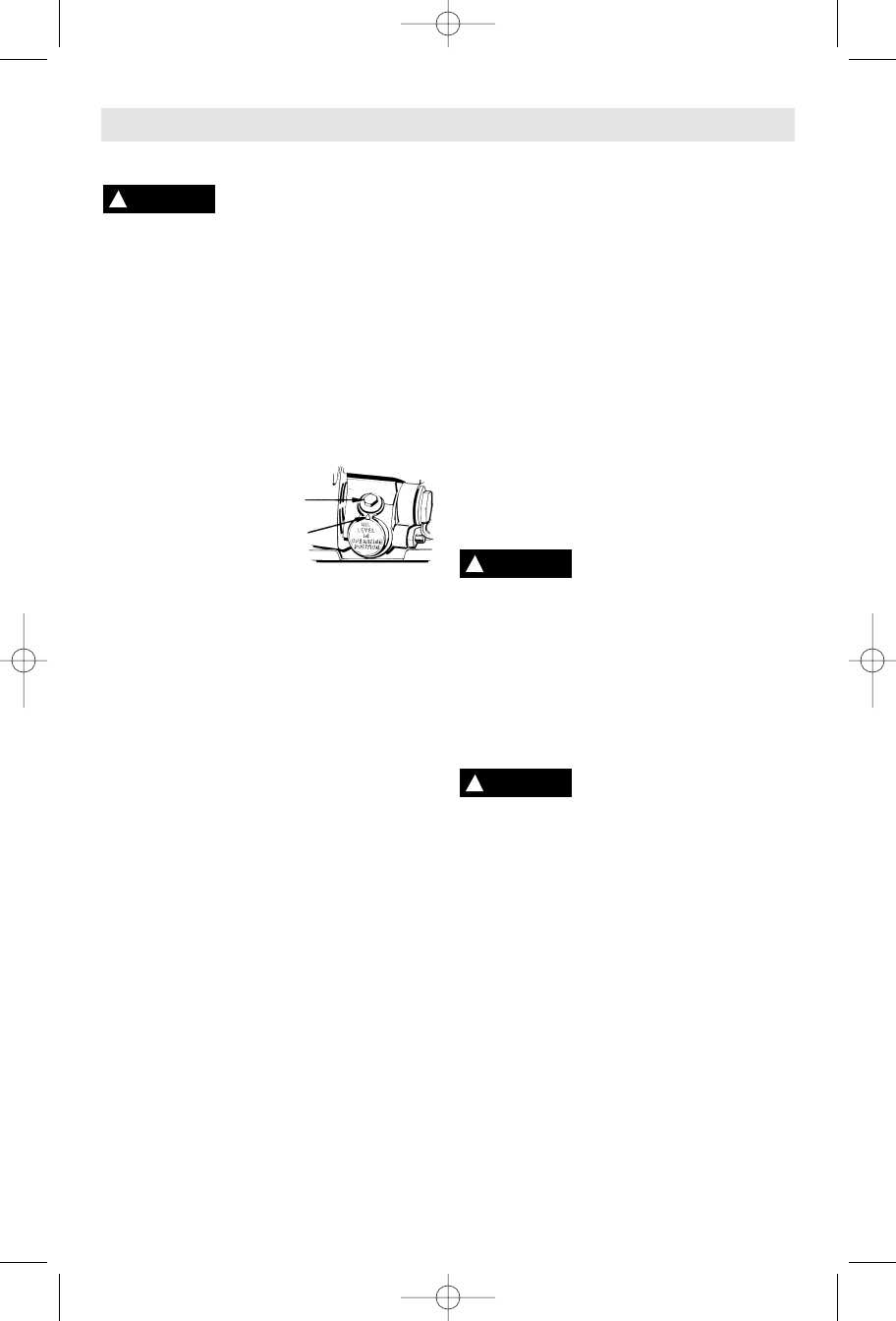
The power cord is a crucial component in electrical devices, providing the necessary connection to a power source. Understanding its wiring is essential for safe operation and maintenance. This section will delve into the basics of power cord wiring, including its structure, function, and common configurations.
Components of Power Cord Wiring
A typical power cord consists of several key elements. These include conductors, insulation, and connectors. The conductors are responsible for carrying electrical current, while the insulation protects users from electrical shock. Connectors are used to link the cord to the device and the power outlet.
Common Wiring Configurations
There are various wiring configurations depending on the type of device and its power requirements. Understanding these configurations can help in troubleshooting and repairs. Below is a table outlining common configurations and their functions:
| Wiring Configuration |
Function |
| Two-wire system |
Used in basic appliances, providing live and neutral connections. |
| Three-wire system |
Includes a ground wire for added safety, commonly used in power tools. |
| Extension cord wiring |
Used to extend reach, often featuring multiple outlets. |
Common Wear Parts and Replacements
In the realm of power tools, certain components are prone to wear over time due to continuous use. Understanding these elements is crucial for maintaining optimal performance and ensuring longevity. Regular inspection and timely replacement can prevent unexpected failures and enhance the tool’s efficiency.
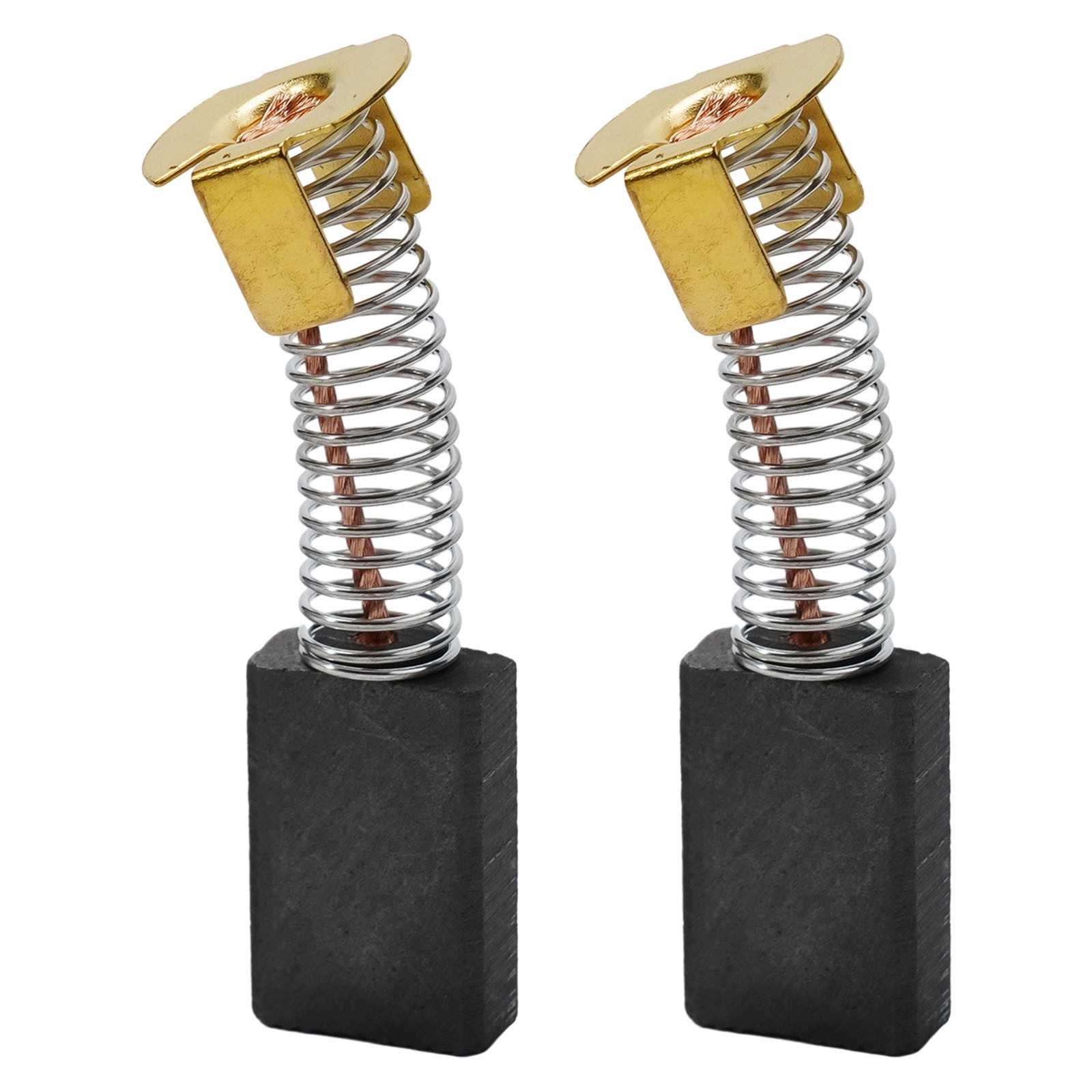
One of the most frequently replaced items is the blade. As it encounters various materials, its sharpness diminishes, leading to less precise cuts. Additionally, the brushes are vital for motor function; worn brushes can result in poor electrical contact, affecting power delivery. It’s also important to keep an eye on the bearing systems, as they support moving parts and, if degraded, can cause operational noise and instability.
Another component to consider is the housing, which may become cracked or damaged after prolonged exposure to dust and debris. Lastly, the switch mechanism is essential for safe operation. A faulty switch can lead to hazardous situations, making it imperative to replace it promptly when issues arise.
Troubleshooting Issues with Key Components
Addressing problems with essential elements of your equipment is crucial for maintaining optimal performance. Understanding common challenges and their symptoms can save time and enhance efficiency. This section will explore several significant components, helping you identify and resolve potential issues effectively.
Motor Malfunctions: One of the primary concerns may involve the motor. If the device fails to start or operates intermittently, check for loose connections or damaged wiring. Additionally, overheating can indicate an overloaded motor, which might require adjustments to workload or replacement of faulty parts.
Blade Dullness: A dull blade can severely impact cutting efficiency and quality. Signs of dullness include excessive friction, slow cutting speed, and increased effort needed during operation. Regularly inspecting the blade and replacing it when necessary ensures smooth and precise cuts.
Power Supply Issues: Inconsistent power supply can lead to various problems, including unexpected shutdowns or failure to start. Ensure that the power cord is intact and connections are secure. If the power source appears unstable, consider using a different outlet or checking the circuit for issues.
Safety Switch Problems: The safety switch is designed to prevent accidental activation. If the device does not start, inspect the safety switch for proper functionality. Dirt or debris can hinder its operation, so cleaning the switch may resolve the issue.
By systematically evaluating these key components, you can effectively troubleshoot and maintain your equipment, ensuring reliable performance and longevity.
Maintenance Tips for Your Circular Saw
Proper upkeep of your circular cutting tool is essential for optimal performance and longevity. Regular maintenance not only enhances the efficiency of the equipment but also ensures safety during its use. Here are some effective tips to keep your tool in excellent working condition.
First and foremost, always keep the cutting blade clean and free from debris. A buildup of dust and resin can hinder the cutting efficiency and lead to uneven cuts. Regularly inspect the blade for signs of wear and tear, and replace it if necessary to maintain precise cutting ability.
Additionally, check the motor housing and other components for any signs of wear. Lubricate moving parts as recommended by the manufacturer to reduce friction and prevent overheating. This practice helps in maintaining the smooth operation of the tool, ensuring a longer lifespan.
It’s also important to regularly examine the power cord and plug for any damage. Frayed cords can pose safety hazards, so replace them immediately if any issues are detected. Furthermore, storing the equipment in a dry and clean environment will protect it from rust and corrosion.
Finally, consult the user manual for specific maintenance instructions tailored to your tool. Following these guidelines will help keep your circular saw functioning effectively and safely, providing you with reliable performance for your projects.
