| Exhaust Hose |
Cooling System Parts and Their Role
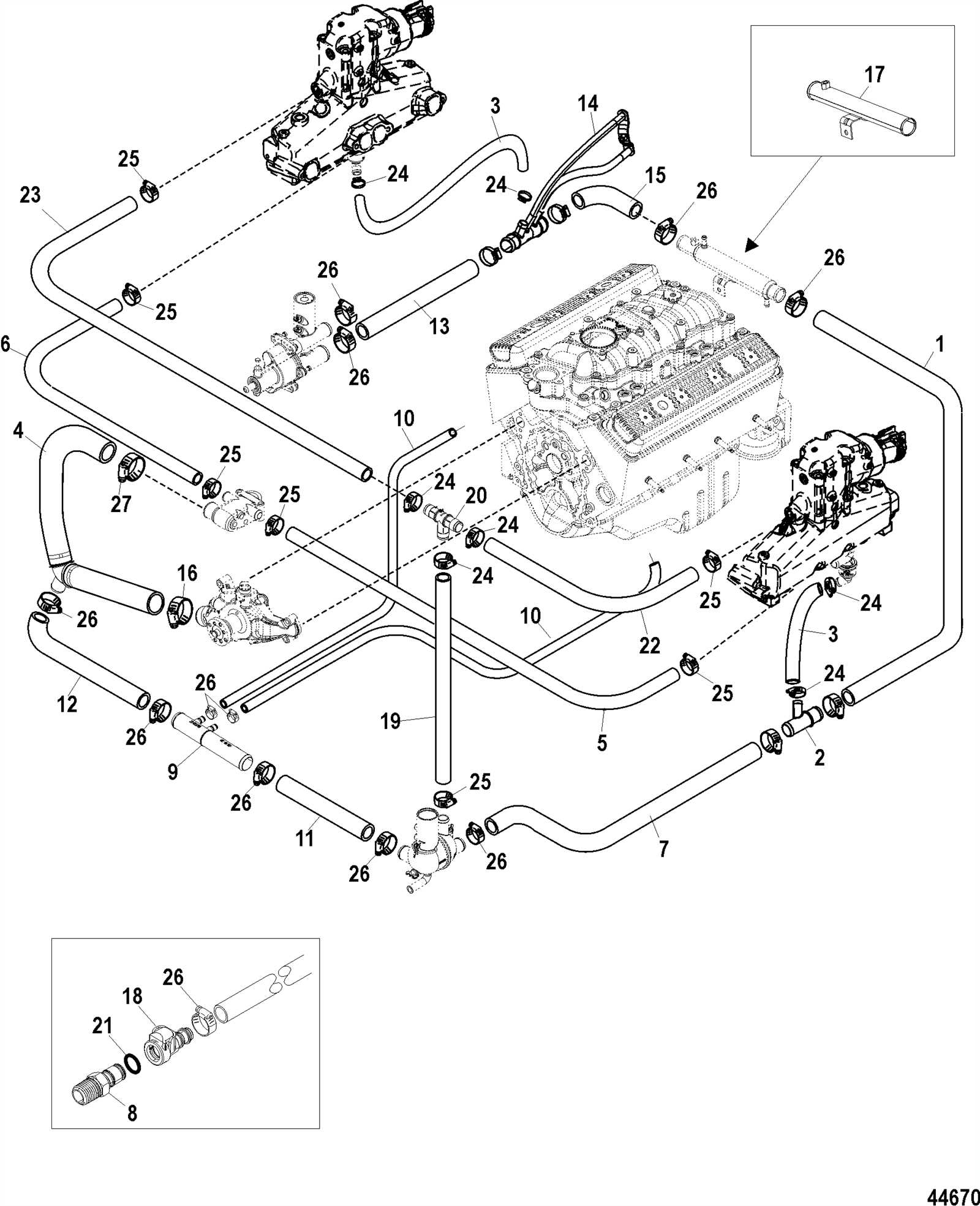
The cooling system is a crucial component in maintaining the optimal temperature of the engine. It ensures that the internal temperature remains within safe limits, preventing overheating and promoting efficient performance. Understanding the various elements of this system helps in comprehending how each part contributes to the overall functionality and longevity of the engine.
Key Components
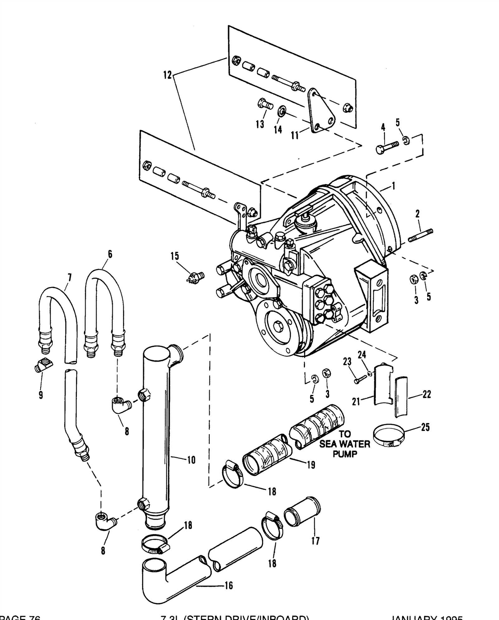
The primary components of the cooling system include the thermostat, water pump, and heat exchanger. The thermostat regulates the flow of coolant, ensuring it circulates only when necessary. The water pump is responsible for moving the coolant through the system, while the heat exchanger facilitates the transfer of heat away from the engine, maintaining a balanced temperature.
Functionality Overview
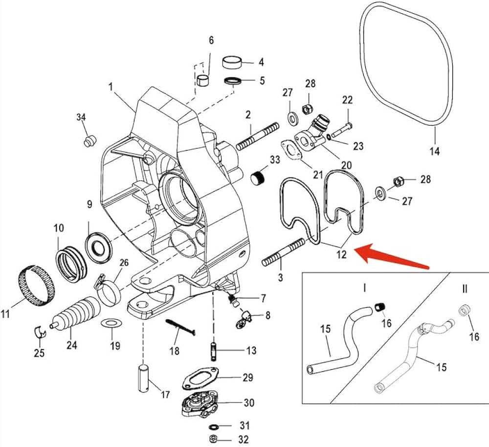
Each element works in harmony to provide effective cooling. When the engine heats up, the thermostat opens, allowing coolant to flow from the heat exchanger. The water pump then circulates this coolant, absorbing excess heat and delivering it back to the heat exchanger, where it is dissipated. This continuous cycle is vital for maintaining optimal engine performance and preventing potential damage.
Fuel Delivery System Breakdown
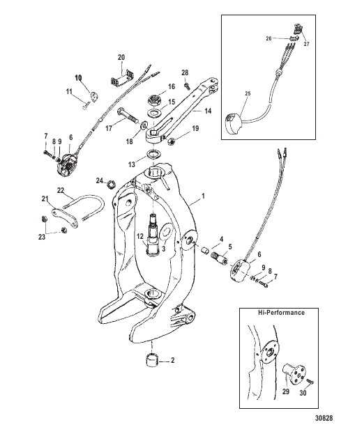
The fuel delivery system is crucial for the efficient operation of an engine, ensuring that the proper amount of fuel reaches the combustion chamber at the right pressure. This system comprises various components that work together to facilitate the intake, storage, and distribution of fuel, allowing for optimal performance and reliability.
| Component |
Function |
| Fuel Tank |
Stores fuel until it is needed by the engine. |
| Fuel Pump |
Moves fuel from the tank to the engine at the required pressure. |
| Fuel Filter |
Removes impurities and contaminants from the fuel before it reaches the engine. |
| Fuel Injectors |
Atomizes fuel and injects it into the combustion chamber at the correct timing. |
| Fuel Pressure Regulator |
Maintains consistent fuel pressure within the system, adjusting as needed for engine demands. |
Understanding the intricacies of this system helps in troubleshooting issues, maintaining performance, and ensuring the longevity of the engine. Regular inspections and replacements of worn-out components are essential to keep the fuel delivery mechanism functioning efficiently.
Propeller Assembly and Its Importance
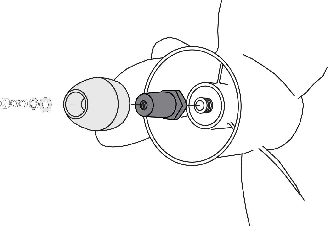
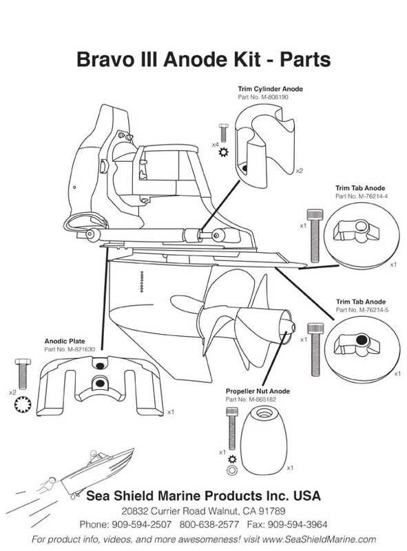
The propeller assembly plays a crucial role in the functionality of marine vessels, influencing both performance and efficiency. This essential component converts engine power into thrust, allowing boats to maneuver effectively in water. Understanding the assembly’s structure and operation is vital for maintaining optimal performance and ensuring safety on the water.
Components of the Propeller Assembly
A typical propeller assembly consists of several key parts that work together seamlessly. Each component is designed to perform a specific function, contributing to the overall effectiveness of the propulsion system. Below is a table summarizing the main components:
| Component |
Description |
| Propeller Blades |
These blades create thrust by moving water backward, propelling the vessel forward. |
| Hub |
The central part of the propeller where the blades are attached, connecting the propeller to the drive shaft. |
| Shaft |
Transmits power from the engine to the propeller, allowing for rotation and thrust generation. |
| Nut and Washer |
Secures the propeller to the shaft, ensuring stability and preventing loosening during operation. |
Significance of Proper Maintenance
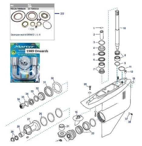
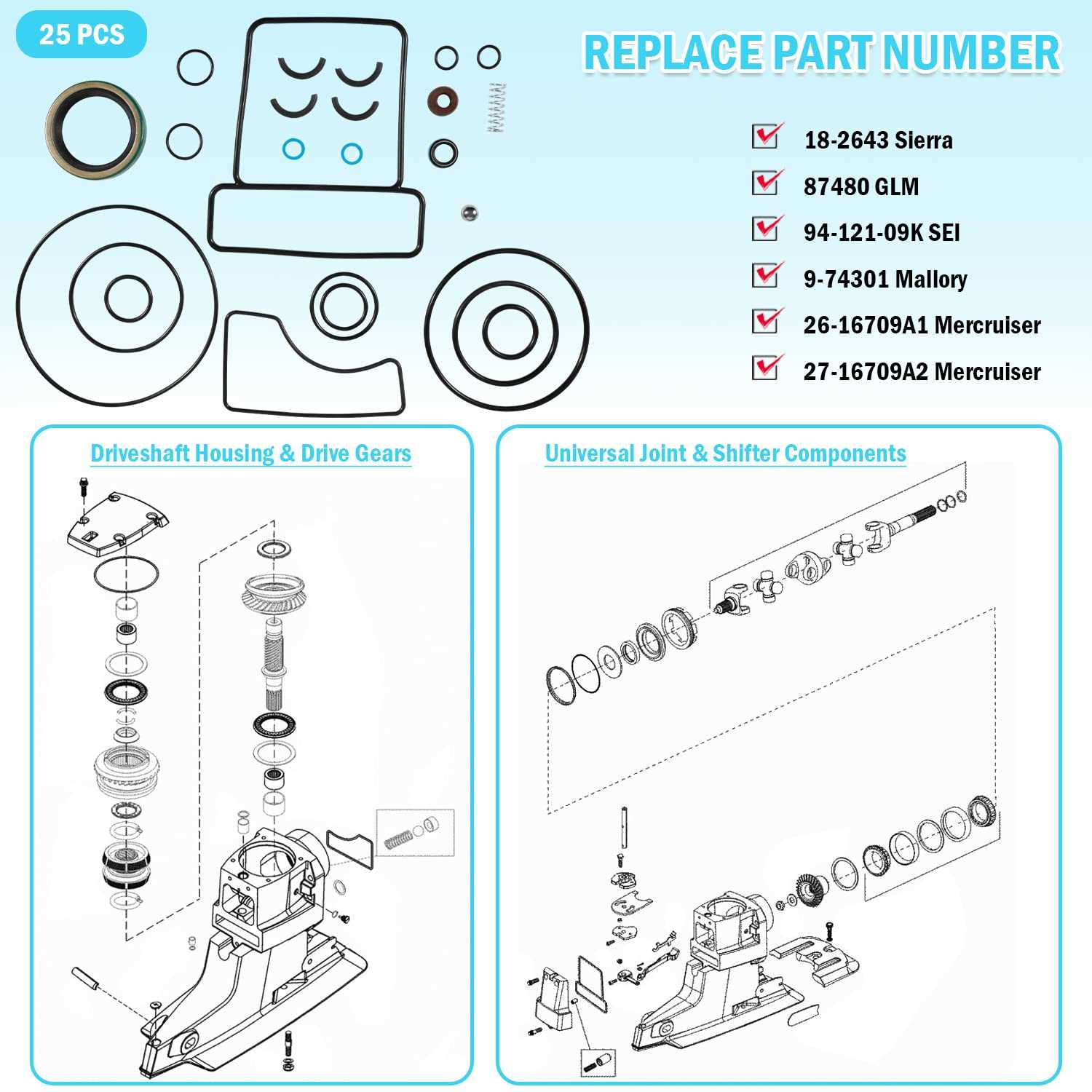
Regular inspection and maintenance of the propeller assembly are essential for optimal vessel performance. Damaged or worn components can lead to decreased efficiency, increased fuel consumption, and potential safety hazards. By ensuring that each part is in good condition, boat owners can enhance performance and prolong the lifespan of their vessels.
Understanding the Trim and Tilt Systems
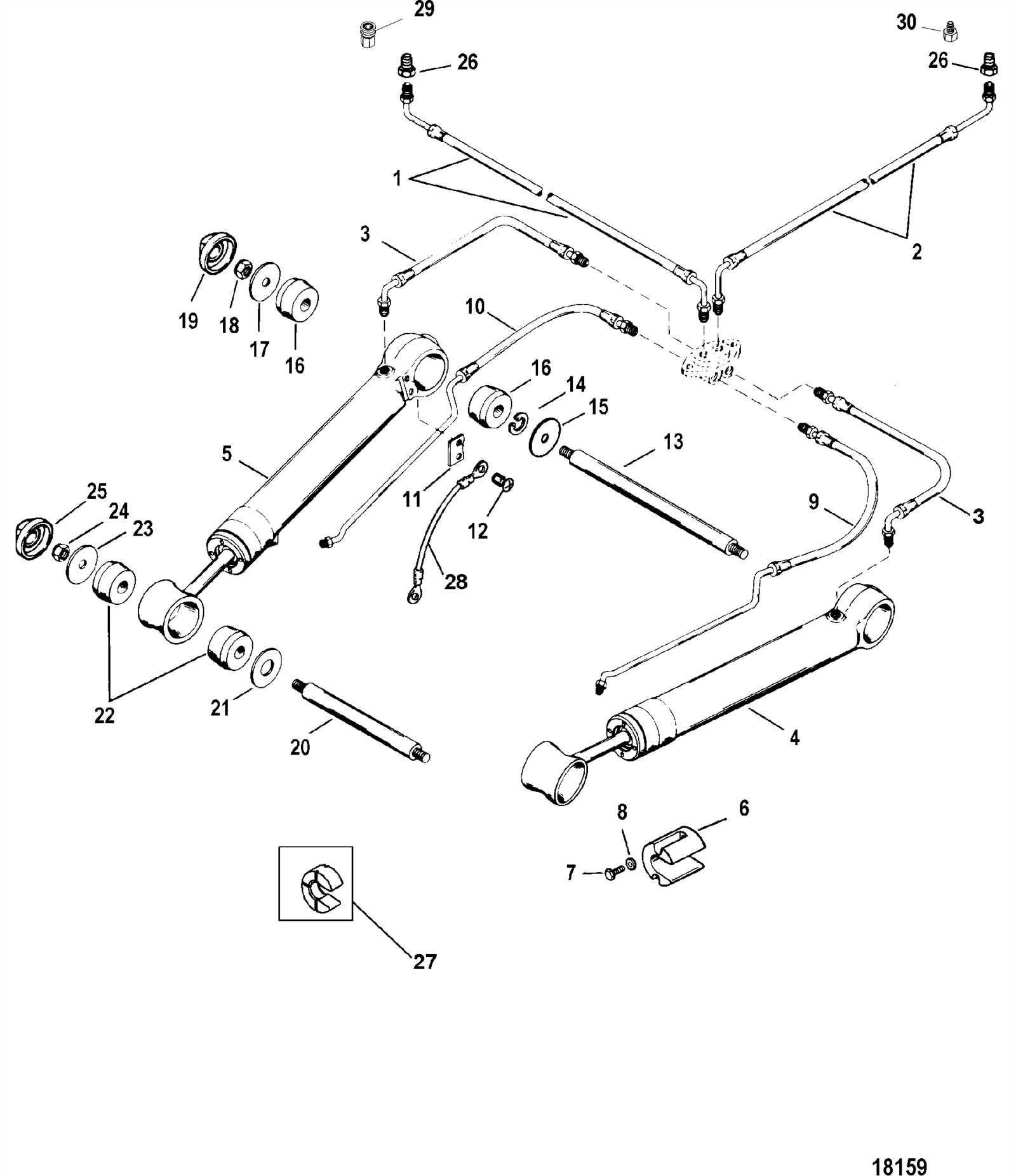
The trim and tilt mechanisms are essential components in enhancing the performance and maneuverability of watercraft. These systems allow for adjustments in the angle of the engine relative to the water surface, thereby optimizing efficiency during navigation. By altering the trim, boat operators can improve fuel consumption, reduce drag, and achieve smoother rides in varying water conditions.
Typically, these systems utilize hydraulic or electric actuators to facilitate the elevation and lowering of the engine unit. This functionality is vital for adapting to different operational scenarios, such as cruising or docking. Understanding how these mechanisms operate can significantly impact a vessel’s handling and overall performance.
| Component |
Description |
| Hydraulic Pump |
Generates pressure to move the actuator, enabling tilt adjustments. |
| Actuator |
Responsible for lifting and lowering the engine, providing the necessary trim changes. |
| Control Switch |
Allows the operator to adjust the trim and tilt positions from the helm. |
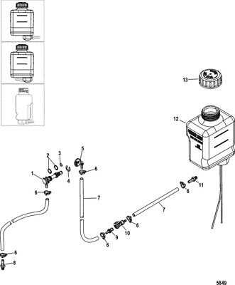
| Fluid Reservoir |
Holds hydraulic fluid essential for the operation of the tilt system. |
Maintaining these systems is crucial for reliable performance. Regular inspections and timely servicing can prevent potential issues and extend the lifespan of the components involved.
Electrical Components of the Bravo 3
The electrical system in marine propulsion units plays a crucial role in ensuring optimal performance and reliability. It comprises various elements that work together to manage power distribution, control functions, and enhance safety on the water.
Wiring Harness: The wiring harness serves as the central hub for electrical connections, facilitating communication between different components. It is essential for maintaining the integrity and functionality of the entire system.
Power Distribution Module: This module is responsible for distributing electrical power to various systems, ensuring that each component receives the necessary voltage and current for proper operation.
Control Switches: Control switches allow the operator to manage essential functions, such as starting the engine and activating various onboard systems. Their design ensures ease of use and accessibility in various conditions.
Sensors: Various sensors monitor critical parameters, including temperature and pressure, providing real-time data to the operator. These sensors contribute significantly to the safety and efficiency of the propulsion unit.
Battery System: The battery system stores energy required for starting the engine and powering electrical devices. Maintaining the health of the batteries is vital for reliable operation, particularly during long voyages.
Understanding these electrical components and their functions helps ensure optimal performance and safety while navigating the waters.
Maintenance Tips for Optimal Performance
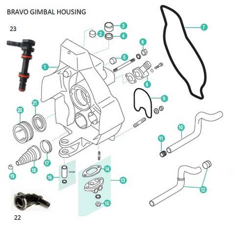
Ensuring peak efficiency of your marine propulsion system requires regular upkeep and attention to detail. Proper maintenance not only extends the lifespan of the components but also enhances overall functionality. By adhering to a systematic maintenance routine, boat owners can avoid costly repairs and enjoy a smoother sailing experience.
Regular Inspection and Cleaning
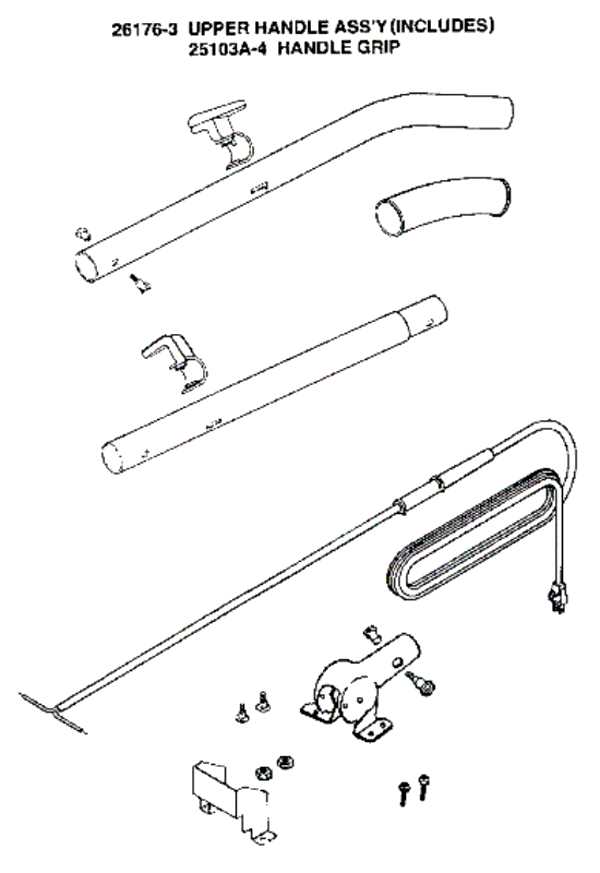
Conducting frequent inspections and cleaning of the equipment is essential. This practice helps identify wear and tear early, preventing potential failures during operation. Pay particular attention to critical areas that may accumulate debris or corrosion.
Fluid Checks and Changes
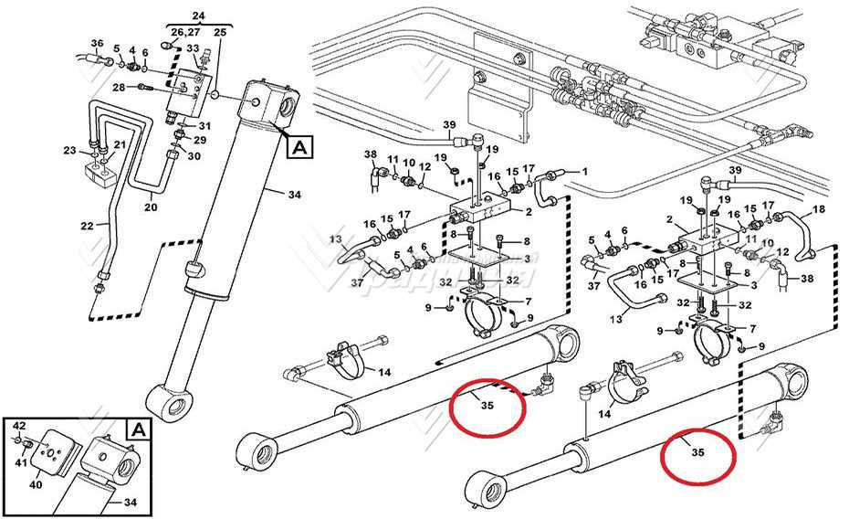
Monitoring and changing fluids at recommended intervals is crucial for optimal performance. The following table outlines key fluids to check regularly:
| Fluid Type |
Recommended Interval |
| Engine Oil |
Every 100 hours of operation |
| Gear Lubricant |
Annually or every 150 hours |
| Coolant |
Every two years |
| Fuel Filter |
Every season |
By following these maintenance guidelines, boat enthusiasts can ensure their systems operate efficiently and reliably, leading to a more enjoyable boating experience.
