When maintaining complex machinery, it’s crucial to understand the intricate relationships between its various elements. Ensuring the optimal functioning of mechanical systems often requires a close look at how the different parts are structured and work together. This becomes particularly important when dealing with equipment designed for large-scale farming and harvesting tasks.
The key to efficient repair and upkeep lies in recognizing how each section connects to form a complete, working unit. Without a clear understanding of these interconnections, even the most seasoned technician could face unnecessary challenges. Identifying each component and its role is the foundation of successful machinery maintenance.
By focusing
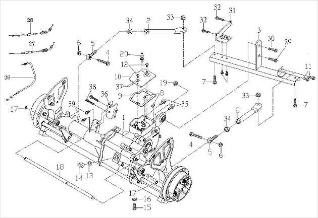
Equipment Component Overview
This section provides a general examination of the key components found in the machinery used for crop cutting and processing. Understanding the various mechanical parts that work together in such equipment helps ensure efficient field operations and long-term durability.
Below is a table detailing the primary assemblies involved in this agricultural machine:
| Component | Function | ||||||||||||||||
|---|---|---|---|---|---|---|---|---|---|---|---|---|---|---|---|---|---|
| Cutter Bar Assembly | Responsible for cutting crops at ground level, ensuring an even trim for optimal processing. | ||||||||||||||||
| Reel Mechanism | Works to lift and feed the crop into the cutting system, ensuring smooth and continuous flow. | ||||||||||||||||
| Rollers |
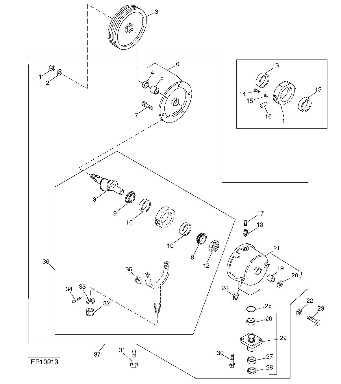
| Component | Function | |||||||||||
|---|---|---|---|---|---|---|---|---|---|---|---|---|
| Input Shaft | Receives power from the drive system and initiates the motion. | |||||||||||
G
Replacing Blades and RollersMaintaining the efficiency of your cutting equipment is essential for optimal performance. One of the critical aspects of this upkeep involves the timely replacement of cutting edges and rollers. Proper maintenance not only enhances functionality but also prolongs the lifespan of your machinery. When it comes to replacing these components, following a systematic approach can make the process more efficient. Here are the key steps to consider:
By regularly replacing blades and rollers, you ensure that your cutting equipment operates smoothly and efficiently, making your tasks easier and more productive. Hydraulic System Parts Explained
The hydraulic mechanism plays a crucial role in the efficient operation of agricultural machinery, facilitating various functions through the use of fluid power. Understanding the components involved in this system is essential for proper maintenance and functionality. Key Components of the Hydraulic SystemThe main elements of the hydraulic system include the pump, reservoir, valves, and actuators. Each component serves a specific purpose, contributing to the overall performance of the equipment. Functionality and Importance
Fluid is drawn from the reservoir by the pump, creating pressure that is then directed through the valves to control the flow. Actuators, such as cylinders, convert this fluid power into mechanical movement, allowing for various operations such as lifting and lowering attachments. Regular inspection and maintenance of these components are vital for optimal performance and longevity. Common Issues with the Drive BeltThe drive belt is a crucial component in agricultural machinery, playing a significant role in power transmission. Understanding the common problems associated with this part can help in maintaining optimal performance and extending the lifespan of the equipment. Regular inspection and timely intervention can prevent minor issues from escalating into significant failures. Signs of Wear and Tear
One of the primary concerns with the drive belt is the gradual wear and tear it experiences over time. This can manifest in various ways, including fraying edges, cracking, and loss of tension. Addressing these signs early can prevent complete failure and ensure the machinery operates smoothly. Improper AlignmentImproper alignment of the drive belt can lead to increased stress on the component, causing premature damage. Misalignment may result from worn pulleys or incorrect installation. Regular checks and adjustments can mitigate this issue, ensuring that the belt runs smoothly and efficiently.
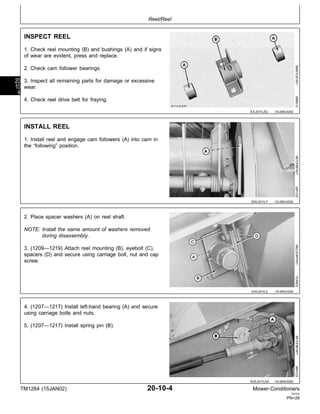
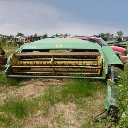
Safety Features of the 1209 HaybineThe machinery in question incorporates several essential safety features designed to enhance operational security and minimize risks during use. These elements play a crucial role in ensuring the well-being of the operator and those in the vicinity while maintaining high efficiency in fieldwork. One of the primary safety mechanisms includes emergency shut-off switches, which allow for quick cessation of operations in critical situations. This feature is vital for preventing accidents and ensuring immediate response in case of an emergency. Moreover, the design includes protective guards that shield moving parts from accidental contact, significantly reducing the likelihood of injuries. These barriers are strategically placed to ensure that they do not interfere with the machine’s functionality while providing maximum safety. Additionally, proper operator training is emphasized to ensure safe handling and effective use of the equipment. The inclusion of comprehensive manuals and instructional materials helps users understand the necessary precautions and operational protocols, further promoting safety on the field. In summary, the integration of these safety features demonstrates a commitment to creating a secure working environment, enabling operators to perform their tasks confidently while minimizing potential hazards. Adjusting the Reel for Optimal PerformanceProper calibration of the reel mechanism is essential for achieving the best results during operation. This adjustment ensures that the cutting process is efficient and effective, allowing for a uniform harvest. By focusing on the optimal positioning and height of the reel, operators can enhance the overall functionality of the equipment. Setting the Height
To begin with, it’s crucial to establish the correct height for the reel. Adjusting this component ensures that it effectively engages with the crop while preventing any damage. Operators should observe the interaction between the reel and the material being harvested, making necessary modifications to achieve the desired outcome. Tuning Reel SpeedIn addition to height adjustments, tuning the reel speed is vital for optimal performance. The speed should be synchronized with the forward motion of the equipment to maintain a steady flow of material. A careful balance allows for efficient cutting while minimizing crop loss, contributing to a more productive operation. Lubrication Points and Greasing RoutineProper maintenance is essential for the optimal functioning of any agricultural machinery. A well-established lubrication schedule ensures that all moving components operate smoothly, reducing wear and tear and prolonging the lifespan of the equipment. Identifying key lubrication points is critical in maintaining efficiency and performance. Key Areas for LubricationFocus on the major pivot points and bearings where friction occurs. Regular greasing of these areas minimizes resistance and enhances the overall operation of the machinery. Pay particular attention to roller bearings, chains, and joints, ensuring they receive adequate lubrication to function effectively. Greasing Schedule
It is advisable to establish a greasing routine based on operating hours or specific intervals, typically every 8 to 10 hours of operation. Regularly check grease levels and apply the recommended type of lubricant, ensuring that no excess is introduced, which can attract dirt and debris. Maintaining a consistent greasing routine is vital for achieving optimal performance. Parts Replacement for Smooth OperationEnsuring optimal performance of agricultural machinery requires regular maintenance and timely substitution of worn-out components. This approach not only enhances the efficiency of operations but also extends the lifespan of the equipment. Understanding the key elements that need attention can significantly impact productivity during the harvesting season. Key Components to Monitor
Replacement RecommendationsWhen it comes to replacements, consider the following:
Signs of Wear in Key Components
Identifying the indicators of deterioration in crucial elements of agricultural machinery is essential for maintaining optimal performance and ensuring longevity. Regular inspections can reveal signs that components may need attention, preventing unexpected breakdowns and costly repairs. Common Indicators of Deterioration
Performance Changes
|
