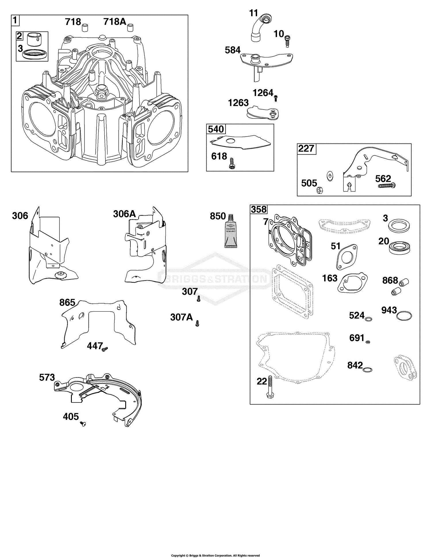
Exploring the intricacies of mechanical assemblies is essential for effective maintenance and repair. This section provides a comprehensive look at the arrangement and function of various elements within these systems. By gaining insight into how each piece interacts with others, users can enhance their troubleshooting skills and ensure optimal performance.
Each assembly consists of numerous components that work together seamlessly. Understanding their layout is crucial for anyone involved in repairs or replacements. Through detailed representations, one can easily identify each element’s role, making it simpler to address any issues that may arise.
Familiarizing oneself with these visual aids allows for quicker diagnostics and more efficient repairs. Knowledge of the configuration not only aids in resolving problems but also in performing regular maintenance, ensuring longevity and reliability of the equipment.
Understanding Component Schematics
Component schematics serve as a visual representation of the relationships and functions of various elements within a system. These illustrations simplify the understanding of complex assemblies by breaking down each part’s role, making it easier for users to grasp how everything interacts. Whether you are troubleshooting an issue or performing maintenance, comprehending these diagrams is essential for effective operation.
The Importance of Visual Representation
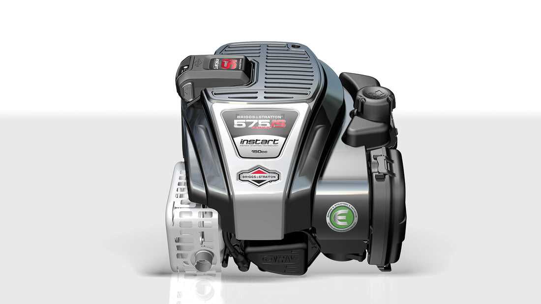
A well-designed schematic provides clarity, allowing individuals to quickly identify components and their connections. This clarity is invaluable during repairs or modifications, as it eliminates guesswork and enhances accuracy in handling different parts. Moreover, these illustrations often include labels and codes that further aid in understanding each element’s specifications and functions.
Key Elements to Note

When studying component schematics, pay attention to the following key aspects:
| Element | Description |
|---|---|
| Symbols | Visual representations of various components, each symbol indicating a specific part. |
| Connections | Lines that demonstrate how components are linked, indicating the flow of power or signals. |
| Labels | Textual descriptions that clarify the identity and function of each component. |
| Notes | Additional information or instructions that provide context for the components or connections. |
Identifying Key Engine Parts
Understanding the fundamental components of an engine is essential for effective maintenance and troubleshooting. Each element plays a crucial role in the overall functionality, contributing to performance and efficiency. By familiarizing oneself with these essential elements, one can ensure the longevity and optimal operation of the engine.
Main Components Overview
The core of any engine consists of several vital elements. The crankshaft transforms linear motion into rotational energy, while the cylinder houses the combustion process. Additionally, the camshaft regulates the timing of valve openings and closings, ensuring efficient airflow. Recognizing these components is vital for diagnosing issues and performing repairs.
Supporting Parts
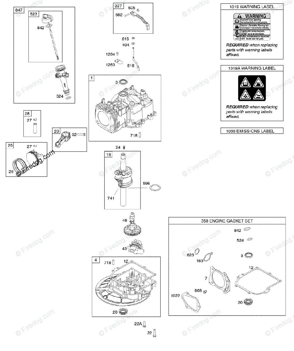
In addition to the main components, various supporting elements enhance the engine’s performance. The fuel system, including the carburetor or fuel injection, is responsible for delivering the right mixture of air and fuel. Meanwhile, the ignition system initiates combustion, providing the power needed for operation. Understanding these supporting parts aids in achieving a well-functioning engine.
How to Read a Parts Diagram
Understanding an illustration that represents various components is essential for effective maintenance and repair tasks. Such visuals simplify the identification of individual pieces, allowing users to navigate the assembly with ease. Familiarity with these illustrations can significantly enhance the efficiency of troubleshooting and part replacement processes.
When approaching a component illustration, pay attention to the accompanying labels and numbers. These typically correspond to specific parts, making it easier to locate and reference them. Often, the visual is organized in a way that groups related elements, providing a clearer overview of the assembly.
| Symbol/Number | Description |
|---|---|
| 1 | Fuel Tank |
| 2 | Engine Block |
| 3 | Air Filter |
| 4 | Oil Cap |
By closely examining the illustration and using the reference chart, users can easily identify and procure the necessary components. This understanding not only facilitates repairs but also encourages proactive maintenance practices.
Exploring Maintenance Components
Understanding the essential elements that contribute to the upkeep of equipment is crucial for optimal performance. These components play a vital role in ensuring longevity and efficiency, making regular examination and maintenance necessary.
Key aspects of maintenance components include:
- Filters: Critical for trapping contaminants, ensuring clean operation.
- Lubricants: Necessary for reducing friction and wear between moving parts.
- Belts and Cables: Important for the transmission of power and motion.
- Seals and Gaskets: Essential for preventing leaks and maintaining pressure.
Regular inspections of these components can help identify potential issues before they escalate, ultimately saving time and resources.
Recognizing Fuel System Components
The fuel system plays a crucial role in the overall functionality of any internal combustion engine. Understanding its various elements is essential for efficient operation and maintenance. This section aims to highlight the primary components involved in the fuel delivery process, emphasizing their importance and function.
Key Elements of the Fuel System
- Fuel Tank: Stores the fuel required for the engine’s operation.
- Fuel Pump: Responsible for moving fuel from the tank to the engine.
- Fuel Filter: Cleans the fuel by removing impurities before it reaches the engine.
- Fuel Injectors: Spray the fuel into the combustion chamber for efficient mixing with air.
- Carburetor: Mixes fuel with air in the correct ratio for combustion in engines without fuel injection.
Understanding Component Interactions
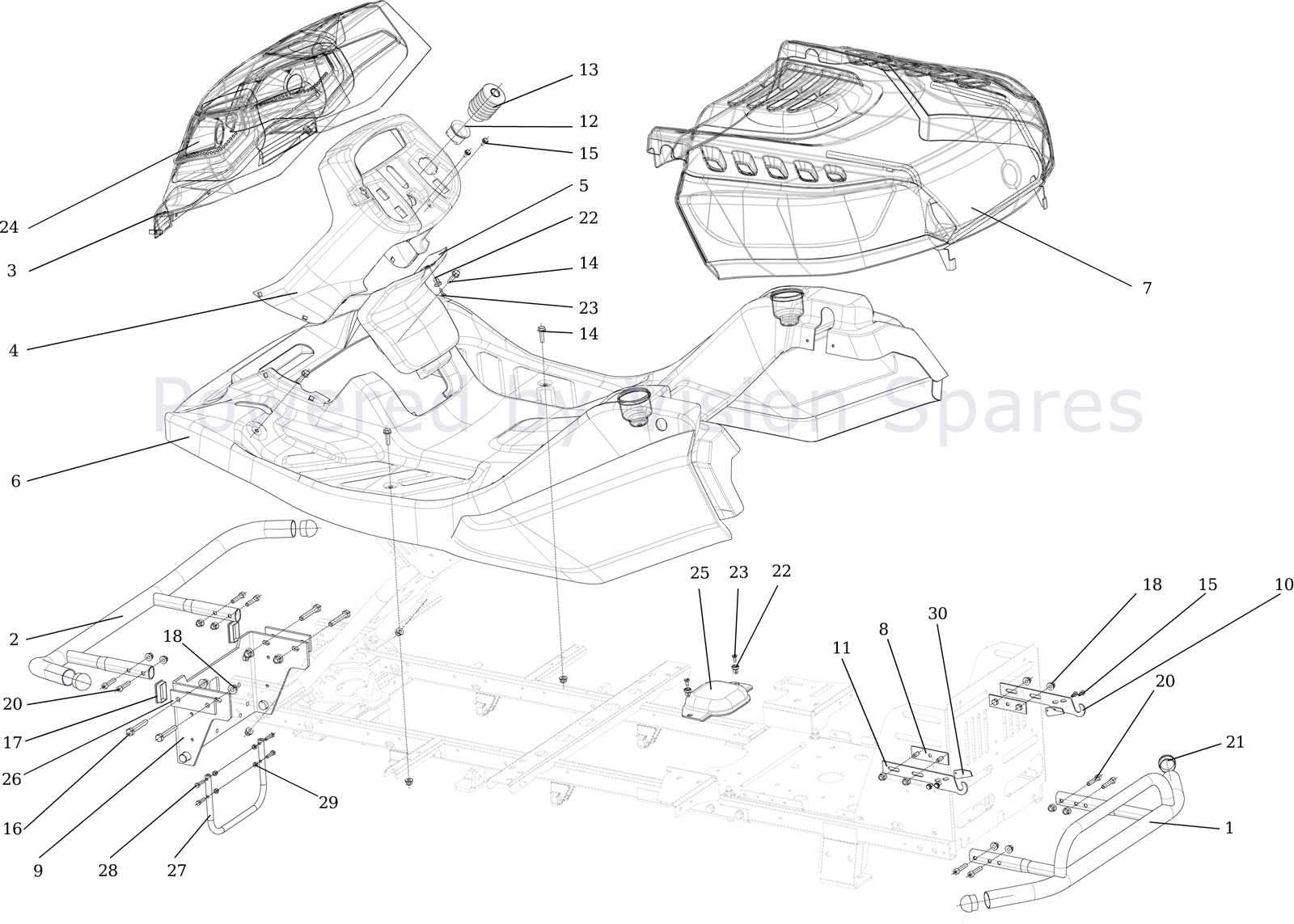
Each part of the fuel system works in unison to ensure the engine receives the proper amount of fuel. A malfunction in any component can lead to poor engine performance or even failure to start. Regular inspection and maintenance of these elements are vital for longevity and efficiency.
Finding Electrical System Parts

Locating components for electrical systems is crucial for effective maintenance and repair. Understanding the layout and connections of various elements within the system aids in identifying the specific pieces needed for restoration or enhancement. By following a structured approach, one can efficiently find the right items to ensure optimal performance.
Identifying Key Components
To successfully locate essential elements, it is important to familiarize yourself with the main components of the electrical system. Each element plays a vital role, and knowing their functions can simplify the search process. Whether it’s a connector, switch, or any other unit, understanding where they fit into the overall framework is key.
Utilizing Reference Materials
Reference materials, such as manuals or online resources, can provide valuable insights into the specific components required. These materials often contain illustrations and descriptions that can guide users in finding the right items. Leveraging these resources can save time and ensure accuracy in selecting the appropriate components.
| Component Type | Description | Function |
|---|---|---|
| Switch | Controls the flow of electricity | Turns the system on/off |
| Connector | Joins two or more electrical circuits | Ensures proper connectivity |
| Fuse | Protects the circuit from overloads | Prevents damage by breaking the circuit |
Common Issues with Engine Components
Engine components can encounter a variety of problems that may affect overall performance and efficiency. Understanding these common issues can help in timely diagnosis and maintenance, ensuring the longevity and reliability of the machinery.
One frequent concern is overheating, which can result from insufficient lubrication or a malfunctioning cooling system. This condition can lead to severe damage if not addressed promptly.
Another issue is fuel inefficiency, often caused by clogged filters or improper fuel mixture. This can lead to increased operational costs and reduced effectiveness of the engine.
Wear and tear of moving parts is also a prevalent problem. Regular inspections can help identify components that need replacement, preventing further damage and costly repairs.
Lastly, vibration can indicate misalignment or imbalanced components. Addressing this issue quickly is crucial to maintain smooth operation and prevent potential breakdowns.
Replacing Worn-Out Elements
Over time, components within machinery can become degraded, leading to decreased performance and efficiency. Addressing these worn-out parts promptly is essential for maintaining optimal functionality. This section will guide you through the process of identifying and replacing these essential elements.
Recognizing signs of wear is the first step. Common indicators include:
- Reduced operational efficiency
- Unusual noises during operation
- Visual signs of damage or corrosion
Once worn elements are identified, follow these steps to replace them:
- Gather necessary tools and replacement components.
- Ensure the machinery is powered off and disconnected from any power source.
- Carefully remove the damaged component, taking note of how it is installed.
- Install the new element in the same orientation as the previous one.
- Reassemble any parts that were removed during the process.
- Test the machinery to ensure proper functionality after replacement.
Regular inspection and timely replacement of worn elements can significantly extend the life of your equipment and enhance its performance.
Decoding Model-Specific Diagrams

Understanding the intricacies of machine schematics is essential for efficient maintenance and repair. These visuals provide a detailed representation of components tailored to specific models, enabling users to identify parts and their functions with ease. By interpreting these illustrations, one can streamline the troubleshooting process and enhance overall performance.
Each schematic is unique, reflecting the design and functionality of the particular model it represents. Recognizing the various symbols and notations used in these representations is crucial for accurate analysis. With practice, users can quickly familiarize themselves with these elements, paving the way for effective service and optimal usage.
Additionally, cross-referencing these visuals with manufacturer manuals can provide deeper insights into component interactions and assembly processes. This comprehensive understanding not only aids in repairs but also contributes to prolonging the lifespan of the equipment.
Using Diagrams for Troubleshooting
Visual representations can be invaluable tools when diagnosing issues with machinery. These illustrations provide a clear overview of components, allowing users to pinpoint malfunctions quickly. By offering a comprehensive view of the assembly, they facilitate a better understanding of how different elements interact.
When faced with a malfunction, consulting these visuals can lead to faster identification of the root cause. They help users trace connections and assess the functionality of individual parts. With a well-organized illustration, the troubleshooting process becomes more efficient, enabling users to focus on the most likely sources of the problem.
Moreover, utilizing these visuals can enhance the learning experience for individuals who are less familiar with the machinery. They serve as educational tools, guiding users through the system’s layout and helping them develop problem-solving skills. In the end, leveraging such resources not only aids in quick resolutions but also fosters a deeper understanding of the equipment.
Best Practices for Part Identification
Accurately identifying components is essential for effective maintenance and repair. Employing systematic approaches ensures that you select the correct items needed for replacements or enhancements.
Utilize Visual References

One of the most effective ways to recognize components is through visual aids. These can include:
- Illustrated guides that showcase various parts
- High-quality images from manufacturers
- Online resources featuring exploded views of assemblies
Maintain an Organized Inventory
Keeping your inventory systematically organized enhances efficiency and accuracy. Consider these practices:
- Label all items clearly with descriptions and specifications
- Group similar components together to facilitate quick access
- Regularly update inventory records to reflect any changes