stihl ms211c parts diagram

Maintaining and repairing a chainsaw requires a clear understanding of how its various components fit together. By having a detailed visual reference, you can ensure that every element is correctly placed, minimizing potential issues during assembly or disassembly. This guide aims to provide an organized look at essential mechanisms, offering clarity for both beginners and experienced users.

Understanding the internal and external mechanisms of your cutting tool allows for more efficient repairs and adjustments. Whether you are troubleshooting a problem or simply performing routine upkeep, this resource helps you identify key parts and their respective functions, ensuring your tool operates smoothly and safely.

Stihl MS211C Parts Overview

This section introduces the key components that make up the structure and functionality of the well-known chainsaw model. Understanding these elements is crucial for proper maintenance and efficient performance, as each element contributes to the overall operation. We will explore the essential elements, providing a clear understanding of their roles in ensuring smooth operation.

Key Components Breakdown
stihl ms211c parts diagram

The main body contains several critical units that work together to deliver power and precision. These units are designed for durability and ease of use, ensuring the tool operates effectively. Each segment plays a distinct role, from powering the engine to controlling the cutting mechanism.

Engine Components and Their Role

The internal mechanisms of a chainsaw engine are crucial for transforming fuel into the energy required to power the tool. Each part has a specific function that contributes to the overall performance, allowing the engine to operate efficiently and reliably. Understanding how these components work together can help maintain optimal performance and prevent potential issues.

Piston and Cylinder

The piston and cylinder form the core of the engine’s power generation system. The piston moves up and down within the cylinder, creating the compression needed to ignite the fuel mixture. This movement drives the crankshaft,

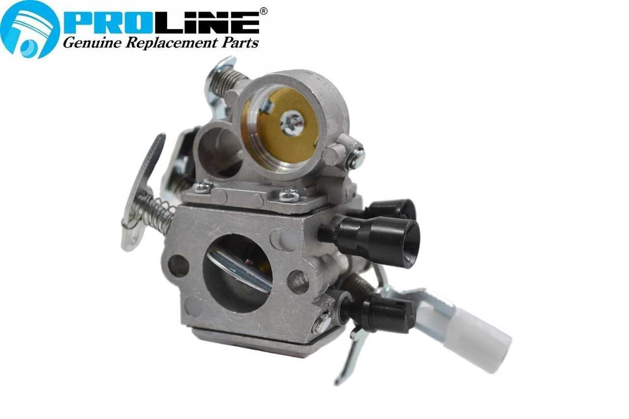
Carburetor Assembly Explained

The carburetor plays a key role in ensuring optimal engine performance by regulating the mixture of air and fuel. Understanding its components and how they interact is essential for anyone looking to maintain or repair small engines. This section provides a clear breakdown of the key elements and their functions within the carburetor assembly.

Main Components of the Carburetor

  • Throttle Valve: This component controls the amount of air that enters the engine, directly influencing the speed and power output.
  • Float Chamber: Responsible for maintaining the fuel at a consistent level, ensuring proper fuel supply during operation.
  • Chain Brake Mechanism Breakdown

    The chain brake system is a critical safety feature designed to protect users during operation. Its main function is to stop the chain’s movement instantly in case of kickback or sudden jerks, reducing the risk of injury. The mechanism works by disengaging the chain drive when triggered by force applied to the hand guard.

    At the core of the system is a spring-loaded band that wraps around the clutch drum. When the hand guard is pushed forward, the spring tightens the band, causing the clutch to halt. This immediate response ensures the chain stops rotating swiftly, even under high pressure.

    Regular maintenance and inspections are necessary to ensure the brake system remains functional. Over time, wear and tear on components such as the spring, band

    Ignition System and Key Parts

    The ignition system plays a crucial role in ensuring the engine starts and runs efficiently. It transforms stored energy into the necessary spark to ignite the fuel-air mixture. Properly maintained components within this system are essential for smooth operation and long-term performance.

    The core of the system includes the spark plug, which generates the spark, and the ignition coil, responsible for converting low-voltage power into high voltage to produce that spark. Additionally, the flywheel works in tandem with the coil, its magnets creating the magnetic field required to induce electrical current.

    Other important elements involve the kill switch, which safely halts the engine, and the wiring that connects all these parts together, ensuring reliable energy transmission. Keeping these components in good condition is critical for optimal functionality and preventing misfires or starting problems.

    Guide Bar and Chain Setup

    The configuration of the guide bar and chain is crucial for optimal performance and efficiency in cutting tasks. Proper alignment and tension ensure smooth operation and enhance the longevity of the equipment. This section provides essential guidance on how to effectively set up and maintain these components, facilitating a safe and productive experience.

    Selecting the Right Guide Bar and Chain

    Choosing an appropriate guide bar and chain combination is vital for achieving desired cutting results. Factors such as length, gauge, and pitch must be considered. The length of the bar affects the cutting capacity, while the gauge and pitch relate to compatibility with the chain. Always refer to the manufacturer’s recommendations to ensure proper fit.

    Installation and Maintenance

    To install the guide bar and chain, start by loosening the tensioning screw and removing the side cover. Place the chain around the drive sprocket, ensuring it fits snugly on the bar. Reattach the guide bar and adjust the tension by turning the screw until the chain fits securely but still moves freely. Regularly check the tension and condition of both the bar and chain to prevent wear and ensure efficient operation.

    Fuel Tank and Venting System

    The fuel reservoir and its associated venting mechanism play a crucial role in the operation of outdoor power equipment. These components ensure that fuel is stored safely while allowing for proper airflow to prevent pressure build-up. An effective system facilitates smooth fuel delivery to the engine, which is essential for optimal performance.

    The fuel tank is designed to hold a specific amount of fuel, protecting it from external elements while preventing leaks. It is typically made from durable materials to withstand harsh conditions. An essential aspect of this component is its venting system, which allows air to enter the tank as fuel is consumed. This process prevents a vacuum from forming, ensuring that the engine receives a consistent fuel supply.

    In addition to standard functionality, the venting system must be maintained to avoid blockages. Clogged vents can lead to fuel starvation, affecting the engine’s ability to start and run efficiently. Regular inspection and cleaning of these components can help prolong their lifespan and ensure reliable performance.

    Air Filter System Structure

    The air filtration mechanism plays a crucial role in ensuring optimal performance and longevity of small engines. By efficiently trapping impurities and preventing them from entering the combustion chamber, it maintains engine efficiency and enhances overall functionality.

    Components of the Air Filtration Mechanism

    • Air Filter Element: The primary component designed to capture dust, debris, and other particulates from the incoming air.
    • Filter Housing: A protective casing that encases the filter element, ensuring a secure fit and preventing contaminants from bypassing the filter.
    • Pre-Filter: An additional layer that provides extra filtration for larger particles, often washable and reusable.
    • Intake Manifold: The pathway through which filtered air enters the engine, contributing to optimal air-fuel mixing.

    Maintenance and Care

    1. Regularly inspect the air filter for dirt and blockages.
    2. Clean or replace the filter element according to the manufacturer’s recommendations.
    3. Ensure the filter housing is free from cracks or damages that could compromise filtration efficiency.
    4. Consider using a pre-filter in dusty environments to extend the life of the main filter.

    Muffler and Exhaust Components

    The efficiency and performance of a power tool are significantly influenced by its exhaust system. This system is designed to direct gases produced during operation away from the engine, reducing noise and emissions. Understanding the various elements involved can help in maintaining optimal functionality and prolonging the lifespan of the equipment.

    Muffler Functionality

    The muffler serves a crucial role in controlling noise levels generated by the engine. It works by dissipating sound waves through a series of chambers, effectively minimizing the loudness associated with the operation. In addition to noise reduction, it also aids in directing exhaust gases in a safe manner, preventing back pressure that could hinder performance.

    Exhaust Components

    Key elements of the exhaust system include the exhaust port, pipes, and the muffler itself. The exhaust port allows gases to escape the engine, while the pipes transport these gases to the muffler. Proper alignment and sealing of these components are vital to prevent leaks and ensure efficient operation. Regular inspection and maintenance can help identify issues such as blockages or corrosion, which can adversely affect performance.

    Clutch Mechanism in Detail

    The clutch mechanism is a crucial component that facilitates the smooth operation of various machinery. It enables the transfer of power from the engine to the cutting tool while allowing for controlled engagement and disengagement. Understanding its functionality and structure is essential for maintaining optimal performance and ensuring the longevity of the equipment.

    Typically, the clutch assembly comprises several key components that work in unison. These include the clutch drum, drive belts, springs, and friction pads. Each part plays a specific role in the mechanism’s overall performance, contributing to its ability to manage torque and speed effectively.

Component Description
Engine Unit The power source that drives the cutting process, providing the necessary force for operation.
Component Function
Clutch Drum Houses the friction pads and engages with the drive belts to transfer power.
Friction Pads Provide the necessary grip to engage the clutch, allowing for power transmission.
Springs Control the engagement force of the clutch, ensuring smooth operation.
Drive Belts Connect the engine to the clutch drum, transmitting power to the cutting tool.

Proper maintenance of the clutch mechanism is essential for preventing wear and ensuring efficient operation. Regular inspection and replacement of worn components can enhance performance and prolong the life of the equipment.

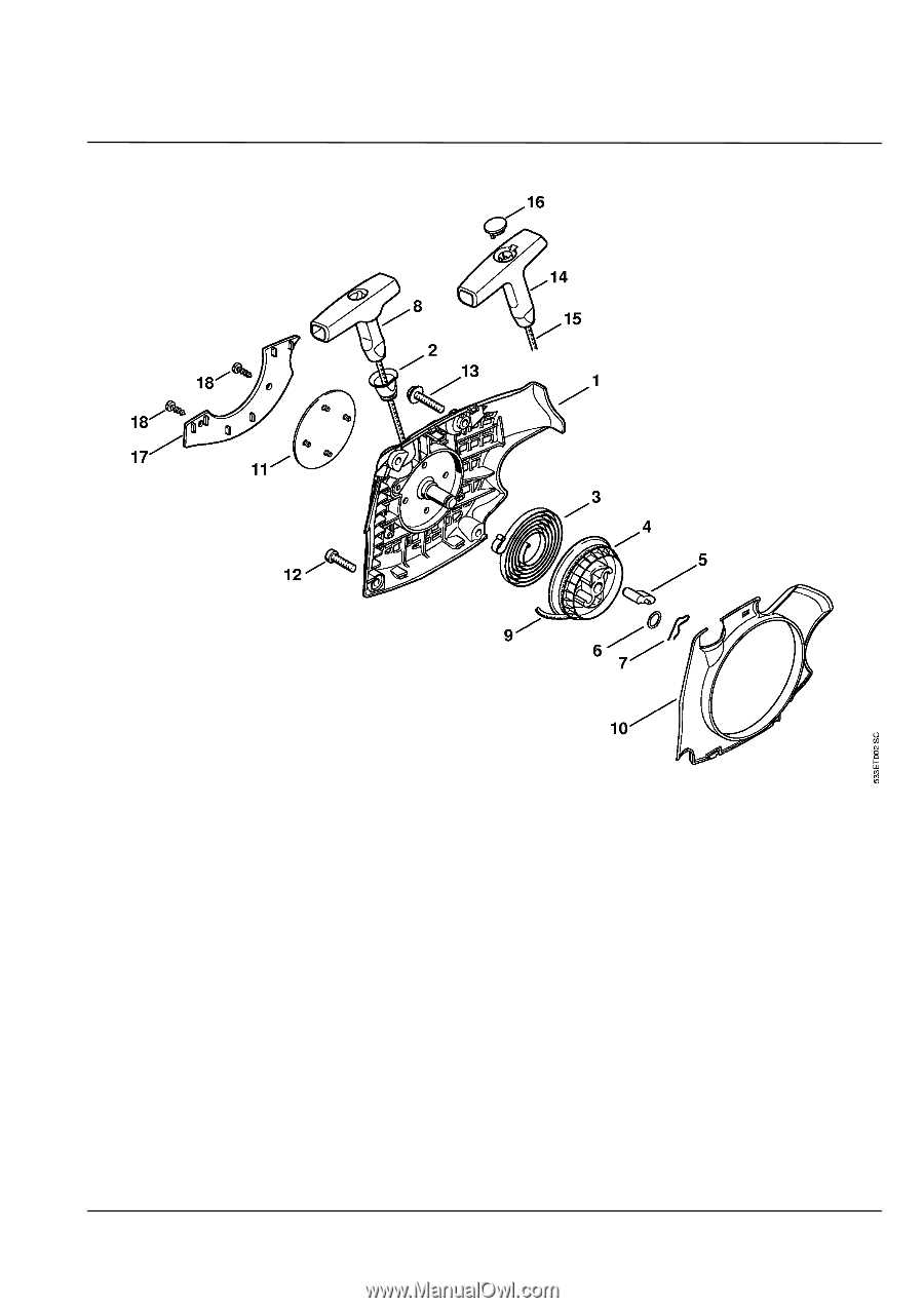
Recoil Starter Functionality

The recoil starter is a critical component in many handheld power tools, serving as the mechanism to initiate the engine’s operation. It allows users to easily start the engine by providing a reliable and straightforward way to engage the ignition system. This essential feature ensures that the equipment is ready for use with minimal effort, making it a vital aspect of user experience.

How It Works

When the operator pulls the starter cord, it activates a spring-loaded device that spins the engine’s flywheel. This action creates the necessary momentum for the ignition process to begin. The recoil system typically consists of a series of pulleys and a spring mechanism that efficiently translates the pulling motion into rotational energy. Once the engine fires, the system retracts the cord back into its housing, ready for the next start.

Importance of Maintenance

Regular upkeep of the recoil starter is essential for ensuring reliable performance. Dirt and debris can accumulate, affecting the smooth operation of the mechanism. Additionally, wear and tear on the cord or spring may lead to starting difficulties. Routine inspections and timely replacements of worn parts can significantly enhance the longevity and efficiency of this crucial starting system.

Oil Pump and Lubrication System

The oil pump and lubrication system play a vital role in ensuring the longevity and efficient operation of a chainsaw. Proper lubrication minimizes friction between moving parts, reduces wear, and enhances overall performance. Understanding the components and functionality of this system is essential for effective maintenance and optimal performance.

Key components of the lubrication system include:

  • Oil Pump: This device is responsible for delivering oil to critical areas of the engine, ensuring that all moving parts are adequately lubricated.
  • Oil Reservoir: A storage tank that holds the lubricating oil, from which the pump draws the necessary fluid.
  • Oil Lines: Tubes that transport the oil from the reservoir to the pump and then to the engine components.
  • Nozzles: These direct the flow of oil precisely where it is needed, allowing for efficient lubrication.

When considering the functionality of the lubrication system, several aspects should be noted:

  1. The oil pump typically operates automatically, adjusting the flow based on the engine’s RPM.
  2. Regularly checking the oil level in the reservoir is crucial to prevent the pump from running dry, which could lead to serious damage.
  3. It is important to use the correct type of oil for the system to ensure optimal lubrication and performance.
  4. Periodic inspection of the oil lines and nozzles is necessary to identify any blockages or leaks that could impede oil flow.

By understanding and maintaining the oil pump and lubrication system, users can enhance the durability and efficiency of their chainsaw, ensuring it operates smoothly for years to come.

Handle Assembly and Vibration Control

The handle assembly plays a crucial role in the overall functionality and comfort of power tools. Proper design and construction not only enhance user experience but also ensure safe operation during extended use. A well-engineered handle can significantly reduce fatigue and improve control, especially in high-performance applications.

Vibration control is an essential feature in the handle assembly, as excessive vibrations can lead to discomfort and long-term health issues. Effective vibration dampening systems help minimize the impact of vibrations on the user’s hands and arms. This section discusses the key components and mechanisms that contribute to effective handle assembly and vibration management.

  • Handle Design: Ergonomic shapes and materials contribute to a comfortable grip, reducing strain during operation.
  • Damping Mechanisms: Various technologies, such as rubber mounts or springs, can absorb vibrations before they reach the user.
  • Weight Distribution: A balanced design helps maintain control and stability, minimizing the effects of vibration.
  • Maintenance Considerations: Regular checks on the handle assembly and its components ensure optimal performance and user safety.

Understanding the importance of handle assembly and vibration control is essential for users seeking to enhance their experience and maintain their tools effectively. By focusing on these aspects, operators can achieve better results while ensuring their safety and comfort.