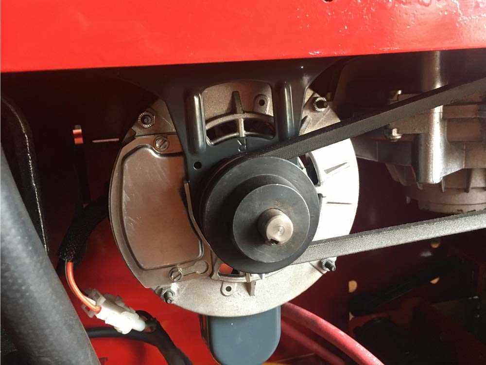
When working with mechanical systems, it is essential to familiarize yourself with the internal configuration and key elements. This helps ensure smooth operation, as well as ease in identifying and resolving any issues that may arise during use. By breaking down the structure, we gain a better understanding of the function and interaction of each element within the system.
Key mechanical components play a vital role in maintaining the integrity of the entire setup. Each section serves a unique purpose, contributing to the overall functionality. Knowing these components and their positions allows for efficient maintenance and troubleshooting, reducing downtime and ensuring longevity.
Exploring the system thoroughly helps in enhancing operational knowledge, making repairs more straightforward and timely. Detailed comprehension of the structure not only benefits technicians but also improves the overall lifespan and performance of the equipment.
Understanding the Layout of Mechanical Components
When analyzing the structure of a mechanical system, it is essential to grasp the relationships between its various elements. Each piece plays a vital role in ensuring the smooth operation and durability of the entire setup. By examining how these elements are organized and connected, one can gain insight into the system’s functionality, which can be useful for maintenance, troubleshooting, and optimization purposes.
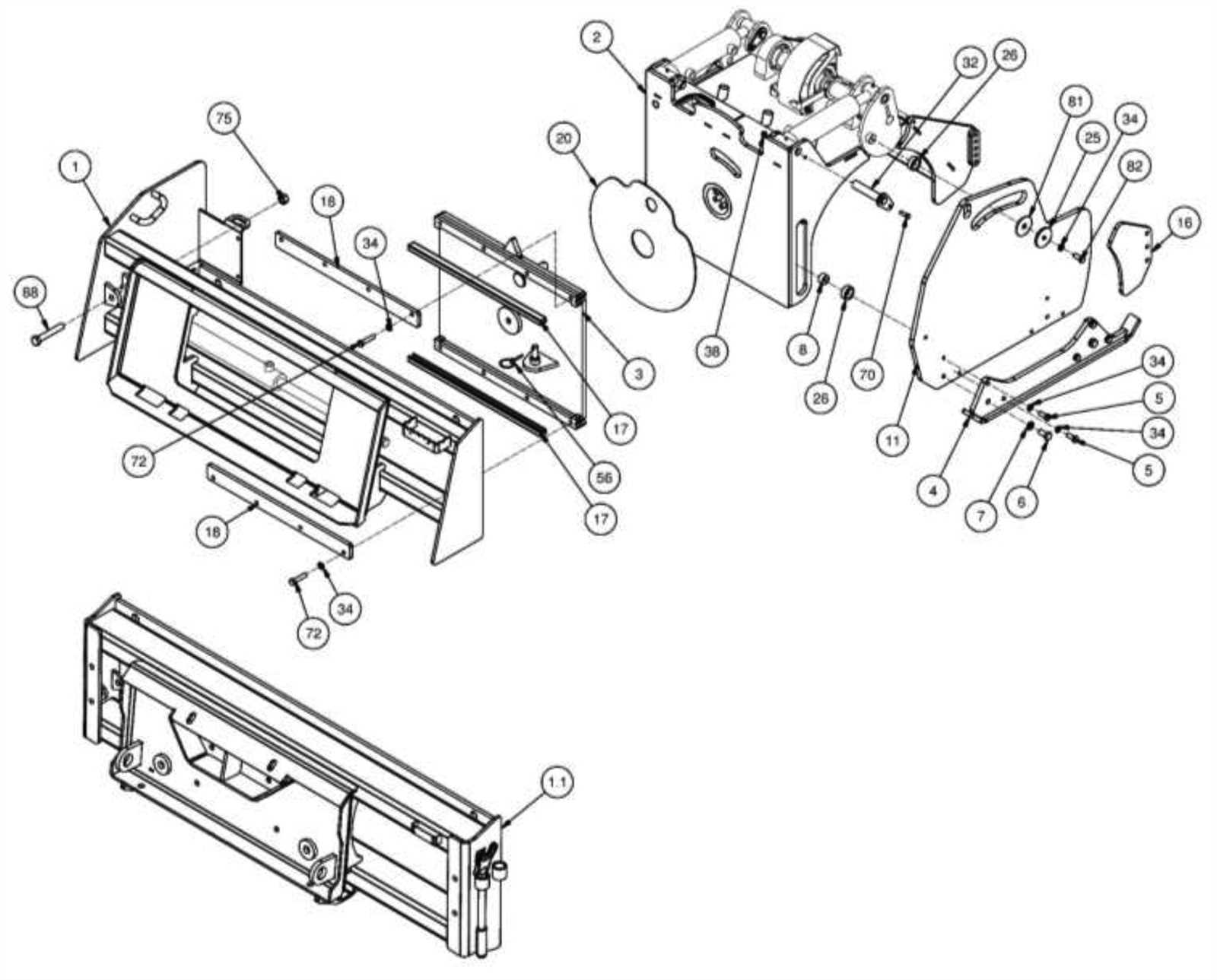
The schematic representation of these components provides a visual guide, helping to identify the positioning, alignment, and interaction of various units. This structured visualization simplifies the task of understanding the system’s complexity and highlights critical areas that may require attention during repair or upgrades.
Key Components of the Coats 5040a
The structure of this equipment consists of several essential elements that work together to ensure smooth operation and efficient performance. These parts are designed to handle various tasks, making the machine both versatile and reliable. Below, we explore the main functional sections that play a vital role in the overall system.
Main Functional Sections
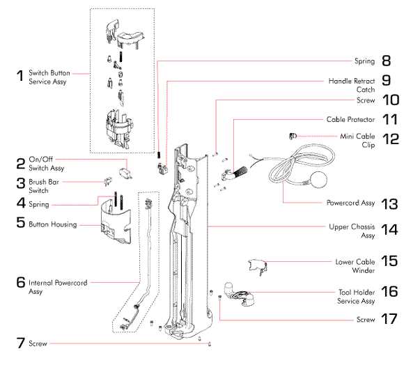
- Control Mechanism – This section allows precise management of the machine’s actions, ensuring everything runs as intended.
- Rotational Unit – A critical part responsible for the movement and adjustment of components during operation.
- Mounting Area – The surface where the primary ta
Exploring the Tire Changer’s Main Assembly
The tire changer is composed of several interconnected elements that work in unison to ensure efficient and safe tire replacement. Each component plays a critical role in the overall functioning, offering both stability and precision during the process. Understanding the core parts of the tire changer’s assembly helps in maintaining and troubleshooting the equipment.
Key Structural Elements
- Base Structure: Provides support and stability to the machine, ensuring that it remains secure during operation.
- Rotating Table: The main platform where tires are placed, allowing for controlled movement during the changing process.
- Mounting Arm: Used to apply pressure to the tire, facilitating the removal
Breakdown of the Hydraulic System
The hydraulic system is a crucial component in ensuring the smooth and efficient operation of various mechanisms. Its primary function revolves around utilizing fluid power to transmit force and manage pressure, allowing for precise movements and controls. Understanding the structure and functionality of this system is essential for maintaining performance and troubleshooting potential issues.
Main Components
The hydraulic system consists of several key elements that work in harmony. These include the pump, which generates fluid flow, and the valves, responsible for directing that flow. Cylinders convert the fluid energy into mechanical motion, while the reservoir holds the hydraulic fluid, ensuring consistent pressure within the system.
Flow and Pressure Control
Control mechanisms play a vital role in managing both the flow and pressure within the system. Valves regulate the direction of the fluid, while pressure relief systems prevent overload by allowing excess fluid to return
Functionality of the Mount and Demount Mechanism
The mounting and demounting mechanism is designed to handle the process of placing and removing various objects securely and efficiently. This system ensures that the transition between installation and removal is smooth, allowing for precise control throughout the procedure. The mechanism combines multiple components that work in unison to accommodate different shapes and sizes.
Mounting involves securing the object into place, ensuring stability during further operations. Specialized tools assist in applying the correct pressure to avoid damage, while maintaining control over the positioning.
Demounting follows a reverse process, where the mechanism allows for the safe release of the object without causing strain on the components. The controlled removal ensures that the item is freed efficiently, reducing risks of improper handling.
Identifying the Electrical Connections
Understanding the electrical connections within machinery is crucial for efficient operation and maintenance. Proper identification of these connections ensures that components function harmoniously and reduces the risk of malfunctions. This section focuses on key aspects of recognizing and managing electrical links.
Key Components to Recognize
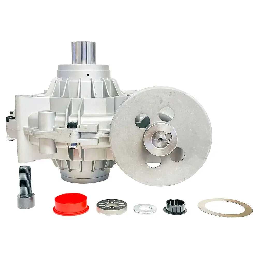
- Power supply terminals
- Grounding points
- Control switches
- Signal connectors
Steps for Effective Identification
- Refer to the manufacturer’s guidelines for electrical schematics.
- Examine the wiring harness for color coding and labeling.
- Use a multimeter to test voltage levels at various points.
- Ensure all connections are secure and free from corrosion.
Safety Features and Their Placement
Ensuring the safety of equipment is paramount in any operational environment. This section explores various safety mechanisms integrated into machinery, highlighting their strategic locations and significance in promoting user protection and operational efficiency.
Key Safety Mechanisms
Different safety features are designed to prevent accidents and protect users during operation. These mechanisms may include emergency stop buttons, safety guards, and automatic shut-off systems, each serving a unique purpose. Understanding their locations helps operators quickly access them when needed.
Placement of Safety Features
The placement of safety elements is crucial for effective operation. Safety guards are typically positioned around moving parts, while emergency stop buttons are often located within easy reach of the operator. This strategic positioning ensures that assistance is readily available during critical moments.
Safety Feature Location Purpose Emergency Stop Button Front panel Immediate shutdown of equipment Safety Guards Around moving components Prevent accidental contact Automatic Shut-off Near the power supply Stop operation during faults Maintenance Tips for Coats 5040a Components
Regular upkeep of machinery components is crucial for ensuring optimal performance and longevity. Adopting systematic maintenance practices can prevent potential issues and enhance the efficiency of your equipment. Here are some essential guidelines to consider for maintaining various elements of your system.
Maintenance Activity Frequency Tips Visual Inspection Weekly Check for wear and tear, loose connections, and any signs of damage. Lubrication Monthly Use appropriate lubricants on moving parts to minimize friction and wear. Component Cleaning Every 3 months Remove dust and debris from all parts to ensure optimal operation. Calibration Annually Ensure all measuring devices are calibrated for accuracy. Understanding the Air Supply System
The air supply system plays a crucial role in various machines, ensuring efficient operation and optimal performance. This system is responsible for delivering the necessary air pressure required for different functions, contributing significantly to the overall efficiency of the equipment. A well-functioning air supply mechanism is essential for maintaining productivity and ensuring longevity in the equipment’s use.
Key Components of the Air Supply System
Several vital components work together to create an effective air supply system. Each part contributes to the overall functionality, and understanding their roles can help in maintaining and troubleshooting the system.
Component Function Compressor Generates the necessary air pressure for operation. Filter Removes impurities and moisture from the air supply. Regulator Maintains a consistent air pressure level. Hoses Transport air from one component to another. Valves Control the flow and direction of air within the system. Maintenance Tips for the Air Supply System
Regular maintenance of the air supply system is essential for preventing issues and ensuring smooth operation. It is important to check for leaks, replace filters periodically, and ensure that all components are functioning correctly. Proper care will not only enhance performance but also extend the lifespan of the equipment.
Overview of the Bead Loosening System
The bead loosening system is a critical component in modern tire mounting equipment, designed to facilitate the safe and efficient removal of tires from rims. This system employs various mechanisms to ensure that the tire bead is properly released, minimizing the risk of damage to both the tire and the wheel during the process.
Functionality and Importance
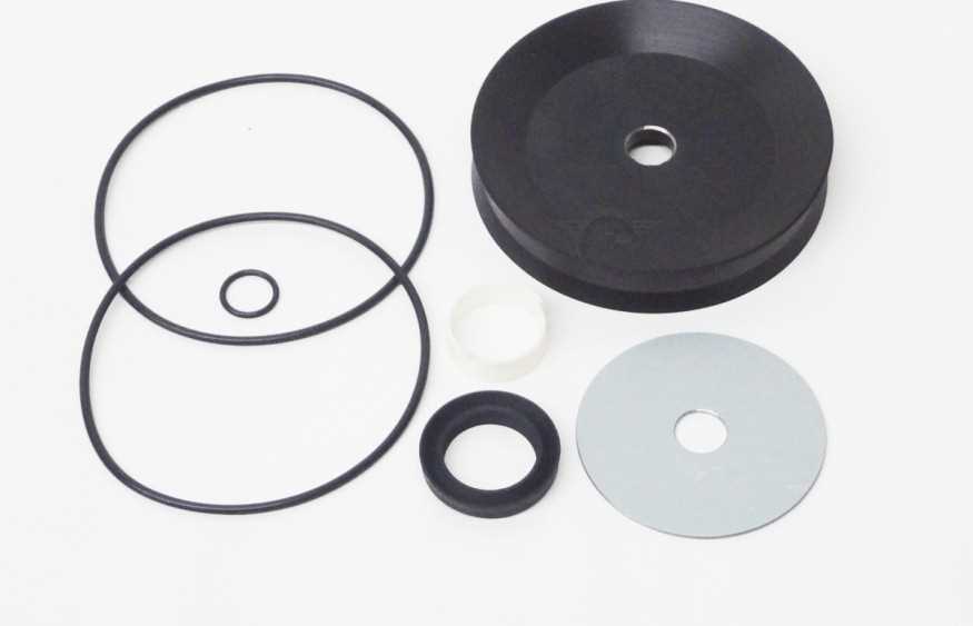
This system functions by applying controlled pressure to the tire bead, allowing it to detach from the rim without excessive force. The careful design of this mechanism is essential for maintaining the integrity of the tire and the wheel, particularly in high-performance applications where precision is paramount.
Key Components
Component Description Bead Lifter A tool that helps in lifting the tire bead away from the rim. Pressure Control Valve Regulates the amount of pressure applied to the tire bead. Actuator Automates the loosening process for efficiency. Proper Adjustment of the Turntable
Ensuring the correct positioning of the rotating platform is essential for optimal performance and efficiency. A well-adjusted turntable contributes to seamless operation, minimizing wear and tear on components while enhancing overall functionality.
To achieve accurate alignment, begin by examining the level of the platform. Use a reliable level tool to confirm that it sits evenly, as an unbalanced surface can lead to operational inconsistencies. If adjustments are necessary, carefully modify the leveling feet until the turntable is perfectly horizontal.
Next, assess the tension of the drive mechanism. Appropriate tension is crucial to prevent slippage and ensure smooth rotation. Adjust the tension by manipulating the associated knobs or levers as specified in the guidelines. Regular monitoring of this aspect can significantly improve the longevity of the equipment.
Finally, check for any misalignment in the connection points. Ensuring that all parts are securely fastened and aligned correctly can help in maintaining stability during operation. Routine maintenance of these adjustments will not only enhance performance but also prolong the life of the machinery.
How to Replace Worn Parts Efficiently
Replacing damaged or degraded components is essential for maintaining optimal performance in any mechanical system. This process not only ensures the longevity of the equipment but also enhances its overall efficiency. By following systematic steps, you can successfully navigate the replacement process with minimal disruption.
Identify the Components Needing Replacement
Begin by thoroughly inspecting the system to pinpoint the specific components that require attention. Look for signs of wear, such as unusual noises, decreased performance, or visible damage. Keeping a checklist can help you stay organized and ensure that no crucial elements are overlooked.
Gather Necessary Tools and Replacement Items
Once you have identified the components to be replaced, gather all required tools and the new items needed for the task. Having everything at hand before starting will save time and prevent frustration during the replacement process. Consider following manufacturer recommendations for compatible replacements to guarantee proper fit and functionality.