Maintaining a lawn tractor requires a thorough knowledge of its essential elements. Whether it’s regular upkeep or addressing potential issues, having a clear understanding of its main structures is critical to ensure optimal performance and longevity.
Efficient troubleshooting and accurate identification of each component play a crucial role in keeping the machine in excellent working condition. This knowledge helps streamline repairs and ensures that the correct solutions are applied to any arising problems.
In the following section, we will delve into the major components of a typical lawn tractor. This will allow you to gain a comprehensive view of how these elements work together to achieve smooth operation and reliability.
Z425 54c Parts Overview
Understanding the key elements of this model’s mechanical structure is essential for proper maintenance and repair. The components are designed to work together to ensure smooth operation, long-term durability, and optimal performance. By familiarizing yourself with the system’s layout, you can easily identify potential issues and take the necessary steps to address them.
Core Components
The primary elements of the system include various functional units that contribute to the overall efficiency. These units are responsible for key operations such as movement, cutting performance, and stability. Each piece plays a crucial role in maintaining the model’s functionality under different conditions.
Key Features
Highlighted by specific performance-enhancing elements, the structure is engineered for durability and efficiency. Each feature is meticulously designed to provide maximum performance while minimizing wear and tear, ensuring that all operational demands are met effectively. Regular inspection and upkeep of these features are critical for prolonged use.
Key Components of the Z425 Mower
The core elements of this lawn cutting machine ensure its smooth operation and reliability. Each component plays a vital role in maintaining efficient performance, allowing for precision in every cut. Understanding these components will help in routine maintenance and troubleshooting.
Engine and Power System
The motor serves as the heart of the machine, delivering the necessary energy for the cutting blades and driving system. Its capacity ensures that the equipment can handle tough grass and extended mowing sessions.
Cutting Deck and Blades
The cutting deck holds the blades responsible for achieving a clean and even trim. The deck’s structure and sharpness of the blades contribute to a flawless finish on various types of terrain. Regular upkeep of these elements is crucial for optimal performance.
Engine Specifications and Maintenance Tips
Understanding the engine’s technical characteristics and following proper upkeep practices is crucial for ensuring the smooth operation and long-term durability of your machine. This section will outline key information about engine performance and provide essential tips for maintaining it in optimal condition.
Core Engine Features
- Four-cycle, air-cooled design for efficient power output.
- Single-cylinder or twin-cylinder options depending on the model.
- Overhead valve (OHV) technology for better fuel efficiency and reduced emissions.
Maintenance Tips
- Check and replace engine oil regularly to prevent excessive wear and overheating.
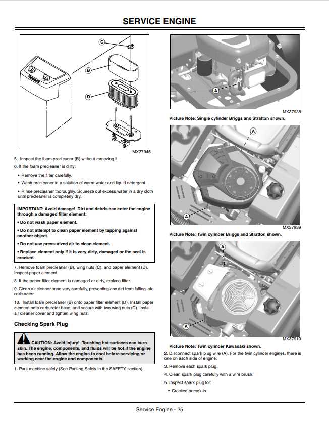
- Inspect and clean the air filter frequently to maintain airflow and fuel efficiency.
- Ensure spark plugs are clean and properly gapped for consistent ignition performance.
- Periodically check the cooling fins for debris buildup, which can lead to overheating.
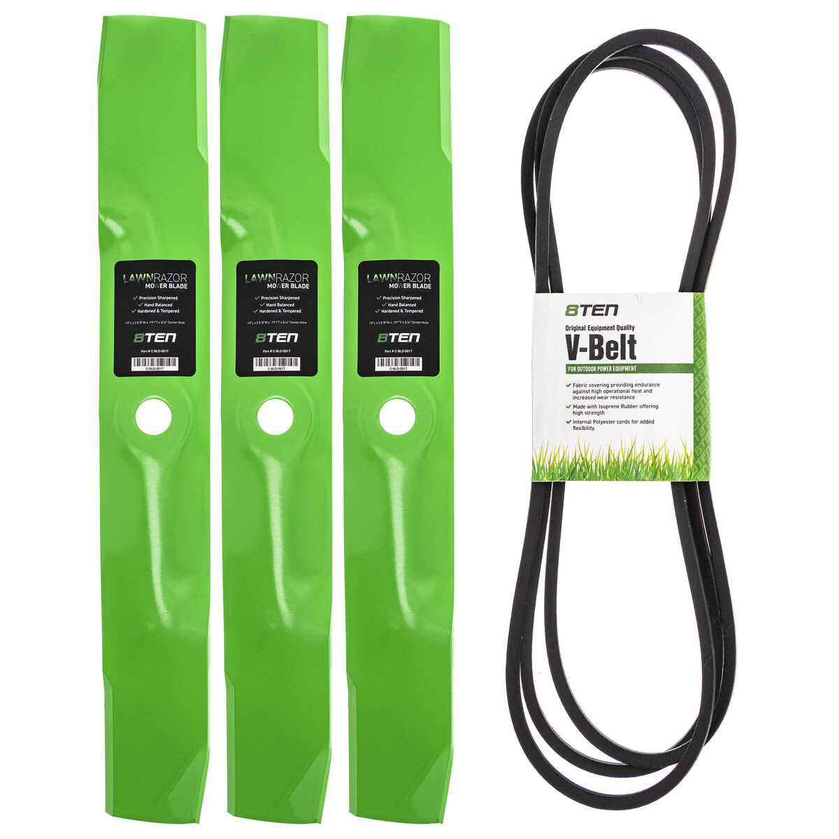
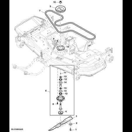
Blade Assembly and Replacement Guide
This section provides an overview of the process involved in assembling and replacing the cutting mechanism of your machine. Understanding the proper techniques and tools required will ensure optimal performance and longevity of the equipment.
To begin, it’s essential to gather the necessary tools, including a socket wrench and safety gloves. Make sure the machine is turned off and adequately secured to prevent any accidental movements during the procedure. Start by removing the existing blade, ensuring that you follow the manufacturer’s guidelines for detachment.
Once the old blade is removed, inspect the spindle and other components for wear or damage. Cleaning these parts can also help maintain their functionality. After ensuring everything is in good condition, position the new blade carefully onto the spindle. Align the mounting holes correctly to ensure a secure fit.
Finally, tighten the bolts securely but avoid overtightening, as this could damage the blade or spindle. Once the assembly is complete, perform a visual inspection to confirm everything is in place. Regular maintenance and timely replacements will enhance the efficiency of your machine and ensure a clean, even cut.
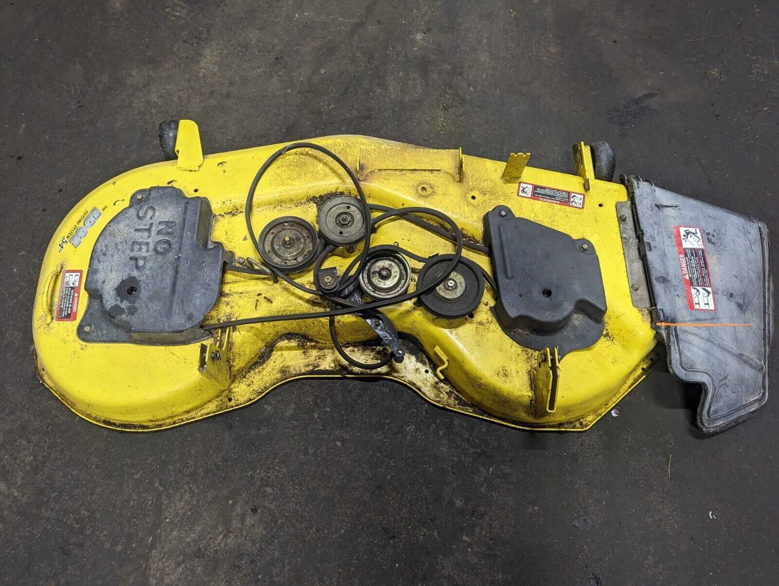
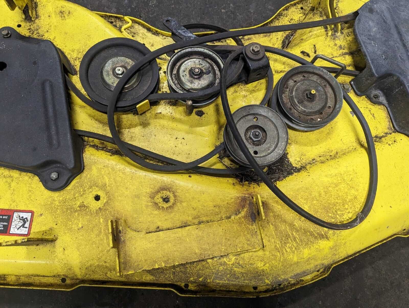
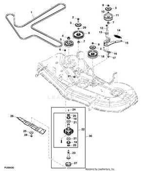
Deck Belt Diagram and Adjustment
The effective functioning of your mowing equipment heavily relies on the proper alignment and tension of the cutting deck’s drive mechanism. Understanding how to adjust and maintain this essential component can enhance performance and prolong the lifespan of your machine.
Proper tension is crucial for the drive mechanism to operate efficiently. If the tension is too loose, it may lead to slippage, while excessive tension can cause undue wear on the components. Here are key steps to consider for adjustment:
- Check the current tension level of the drive mechanism.
- Refer to the manufacturer’s specifications for optimal tension settings.
- Loosen any retaining bolts or fasteners associated with the belt.
- Adjust the tension by either elongating or shortening the drive path as necessary.
- Secure the retaining bolts once the desired tension is achieved.
- Perform a final inspection to ensure everything is aligned properly.
In addition to tension, it’s important to regularly inspect the condition of the belt for signs of wear or damage. Here are some common indicators:
- Cracking or fraying along the edges
- Excessive stretching or deformation
- Visible signs of slipping during operation
Addressing these issues promptly can prevent larger problems and maintain the effectiveness of your mowing equipment.
Transmission Parts and Troubleshooting
This section focuses on the essential components of the drive system and offers guidance on identifying and resolving common issues that may arise. Understanding the various elements involved is crucial for effective maintenance and efficient operation.
Key Components
The drive mechanism consists of several critical elements that work in harmony to ensure optimal performance. Familiarity with these components aids in recognizing potential problems and facilitates troubleshooting.
| Component | Description | Function |
|---|---|---|
| Gearbox | Transmits power from the engine to the wheels | Enables speed adjustment and torque multiplication |
| Drive Belt | Flexible band connecting the engine to the gearbox | Transfers rotational force efficiently |
| Clutch Assembly | Mechanism allowing engagement and disengagement of power | Controls power transfer to the drive wheels |
Troubleshooting Tips
When issues arise within the drive system, timely identification is key to preventing further damage. Here are some helpful strategies:
- Check for unusual noises during operation, which may indicate worn components.
- Inspect the drive belt for signs of wear or fraying.
- Ensure the clutch engages smoothly and does not slip.
Electrical System and Wiring Layout
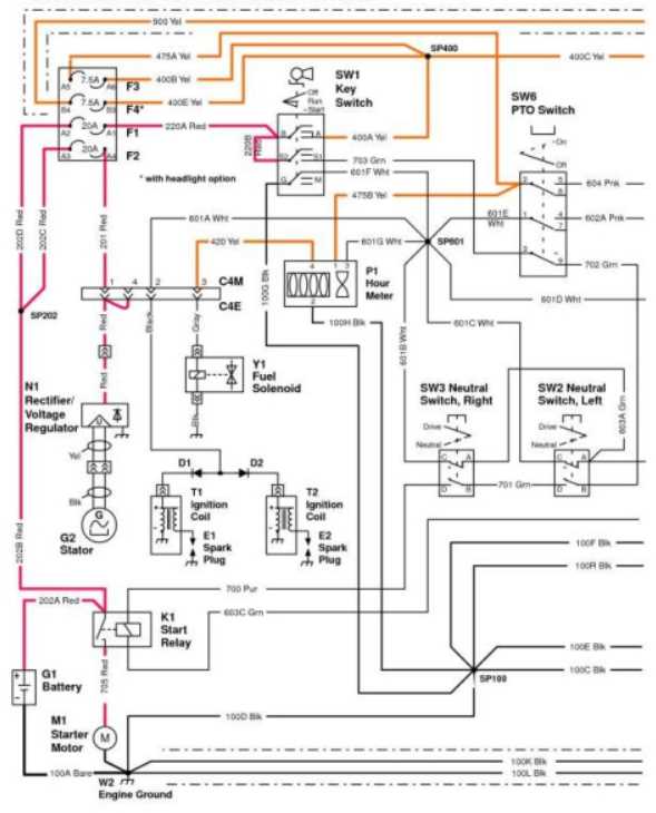
The electrical system of a machine plays a crucial role in its overall functionality and efficiency. Understanding the layout and connections of various components is essential for effective maintenance and troubleshooting. This section provides an overview of the electrical architecture, highlighting key elements that ensure proper operation.
Main Components
- Battery: Supplies power to the entire system.
- Fuses: Protect electrical circuits from overloads.
- Relays: Control the flow of electricity to different components.
- Wiring Harness: Connects various parts and facilitates communication.
Wiring Connections
Proper wiring connections are vital for the seamless operation of the electrical system. The layout should follow specified routes to prevent damage and ensure safety. Here are some important considerations:
- Ensure all connections are secure and free from corrosion.
- Follow the designated wiring routes to avoid interference with moving parts.
- Check for any exposed wires that could pose a safety hazard.
By maintaining a clear understanding of the electrical setup and regularly inspecting connections, users can ensure optimal performance and longevity of the machinery.
Fuel System Parts and Operation
The fuel system plays a crucial role in the efficient functioning of any engine. It is responsible for storing, filtering, and delivering fuel to the engine components, ensuring optimal performance and reliability. Understanding the various elements of this system and how they interact can significantly enhance maintenance and troubleshooting efforts.
- Fuel Tank: The reservoir where the fuel is stored before being transported to the engine.
- Fuel Pump: A vital component that transfers fuel from the tank to the engine at the required pressure.
- Fuel Filter: This element removes impurities and contaminants from the fuel, protecting the engine and other components from damage.
- Fuel Lines: These pipes or hoses transport fuel between the tank, pump, filter, and engine.
- Injector: Responsible for atomizing the fuel and delivering it into the combustion chamber for optimal mixing with air.
- Carburetor (if applicable): A device that blends air and fuel in the correct ratio for combustion, primarily in older engines.
Each of these components must function effectively to ensure smooth engine operation. Regular inspections and maintenance of the fuel system can prevent performance issues and extend the life of the engine. Familiarity with this system allows operators to diagnose problems promptly, ensuring uninterrupted service.
Hydraulic System Diagram for Z425
The hydraulic mechanism is a vital component in various machinery, providing the necessary force to perform tasks efficiently. Understanding the layout of the hydraulic system helps in troubleshooting and maintenance, ensuring optimal performance and longevity of the equipment. This section outlines the essential elements of the hydraulic setup, highlighting its functions and interactions.
Key Components: The hydraulic system consists of several critical elements, including pumps, cylinders, and valves. Each part plays a significant role in transferring and controlling fluid movement, which translates into mechanical power.
Fluid Flow: The flow of hydraulic fluid is meticulously designed to create a smooth operation. By following the designated paths, the fluid circulates through the system, allowing for precise control of various functions. Analyzing these pathways aids in diagnosing potential issues that may arise during operation.
Maintenance Tips: Regular checks and maintenance of the hydraulic system are essential to prevent failures. Keeping an eye on fluid levels, inspecting hoses for leaks, and ensuring that all connections are secure can greatly enhance the reliability and efficiency of the equipment.
Steering Mechanism and Control Parts
The steering system plays a crucial role in the overall functionality of any vehicle, ensuring precise maneuverability and control. This section delves into the components that constitute the steering mechanism and control, highlighting their significance in maintaining stability and responsiveness during operation.
Key Components of the Steering System
Understanding the essential elements of the steering assembly is vital for effective maintenance and troubleshooting. Below are some of the primary components involved:
| Component | Description |
|---|---|
| Steering Wheel | The main control interface used by the operator to direct the vehicle. |
| Steering Shaft | A crucial link that transmits the driver’s input from the steering wheel to the steering gear. |
| Steering Gear | Converts the rotational motion of the steering wheel into linear motion to pivot the wheels. |
| Linkage | A series of rods and connectors that transfer motion from the steering gear to the wheels. |
| Ball Joints | Provide flexibility and allow for smooth movement between the linkage and the wheels. |
Importance of Regular Maintenance
Regular inspection and maintenance of the steering components are vital for ensuring optimal performance and safety. Neglecting these parts can lead to decreased handling capabilities and increased wear on the system, ultimately affecting the vehicle’s stability and driver confidence.
Seat and Comfort Features Breakdown
The seating arrangement and comfort aspects of a machine play a crucial role in enhancing the user’s overall experience. A well-designed seat not only provides support during operation but also contributes to the overall ergonomics of the equipment.
Key comfort features often include:
- Adjustable Seat: Customization options for height and angle to suit individual preferences.
- Cushioning: Quality padding that minimizes fatigue during extended use.
- Armrests: Supportive armrests to enhance comfort and reduce strain.
- Back Support: Ergonomic designs that promote good posture and reduce back discomfort.
- Seat Materials: Durable and weather-resistant fabrics that withstand various conditions.
Incorporating these features not only improves user satisfaction but also boosts productivity, allowing operators to work more efficiently without discomfort.
Tire and Wheel Parts Overview
This section provides a comprehensive look at the components associated with the rolling elements of a vehicle. Understanding these elements is crucial for maintaining optimal performance and ensuring safety during operation. The relationship between tires and wheels significantly influences maneuverability and stability on various terrains.
Key Components of Tires
Tires consist of several vital elements that contribute to their functionality. The tread plays a significant role in providing traction and controlling water dispersion, which is essential for safe navigation. Additionally, the sidewall offers protection against external damage and helps maintain the tire’s structure under pressure.
Wheel Structure and Features
Wheels are designed to support the tire and facilitate movement. The rim serves as the foundation for the tire, while the hub connects the wheel to the vehicle’s axle, ensuring a secure fit. Features such as spokes not only contribute to the aesthetic appeal but also enhance the overall strength and durability of the wheel assembly.