In order to maintain efficiency and prolong the life of any mechanical device, it is essential to have a comprehensive understanding of its inner workings. A detailed breakdown of the various elements that contribute to the tool’s functionality helps both professionals and enthusiasts ensure optimal performance. Knowing how each part interacts within the system can greatly simplify maintenance and repairs.
Whether you’re looking to fix a specific issue or perform routine upkeep, having access to a clear and organized schematic of the device’s core elements is invaluable. This allows you to identify and address potential concerns early on, ensuring the machine continues to run smoothly. Moreover, understanding the interplay of various components can lead to improved decision-making when it comes to replacing or upgrading parts.
By focusing on the intricate design of each element, users can gain a better appreciation for the engineering behind the tool. This not only aids in troubleshooting but also enhances the overall usage experience by
Understanding the Structure of the Makita EK6101
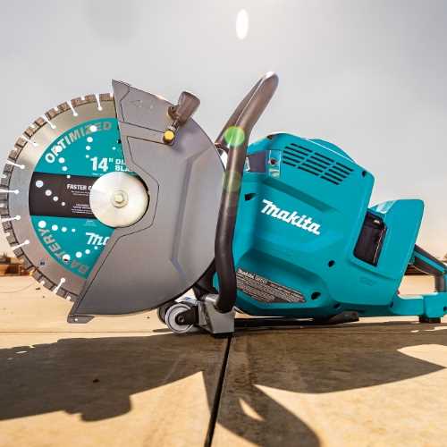
The design of this cutting tool is the result of precision engineering, where every component plays a specific role in its overall functionality. Each part is carefully crafted and positioned to ensure optimal performance during demanding tasks. Understanding how these elements come together is crucial for anyone looking to maintain or repair the machine.
- Engine Layout: The motor is designed to provide high output with reduced emissions, ensuring smooth and efficient operation. The layout ensures that energy is transferred effectively to the cutting mechanism.
- Fuel and Air Systems: Integrated to maintain a balanced mixture for combustion, these systems are essential for maintaining the tool’s power and efficiency.
- Cutting Assembly: The blade and its supporting components are engineered to handle heavy workloads, ensuring precise and consistent cuts across various materials.
Key Components Inside the Makita EK6101
This section focuses on the essential internal elements that make up this high-performance cutting tool. Each part plays a crucial role in ensuring smooth operation, durability, and precise cutting ability. Understanding these components provides insight into the tool’s efficiency and reliability during use.
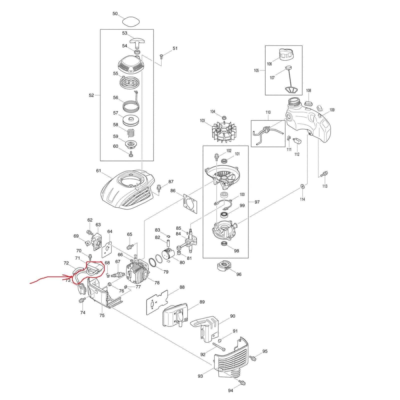
- Engine Unit: The power source that drives the machine, ensuring optimal performance with every use.
- Cutting Blade Assembly: This critical part handles the actual cutting process, designed to withstand tough materials.
- Fuel System: The mechanism responsible for delivering the right amount of fuel to the engine, allowing efficient combustion.
- Cooling System: Keeps the device from overheating during extended operation, ensuring longevity and safety.
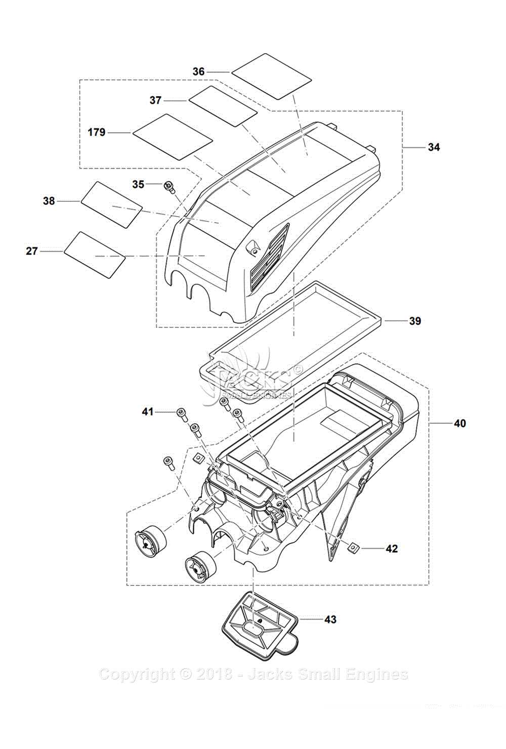
- Air Filter: Protects the engine by preventing debris and dust from entering, thus maintaining consistent performance.
- Fuel Tank: The reservoir where the liquid is stored before being directed to other parts of the system.
- Fuel Lines: Pathways through which the liquid flows from the storage unit to other crucial areas.
- Carburetor: Mixes the liquid with air, regulating the proportion to ensure efficient combustion.
- Fuel Filter: Prevents contaminants from entering the system, protecting delicate components
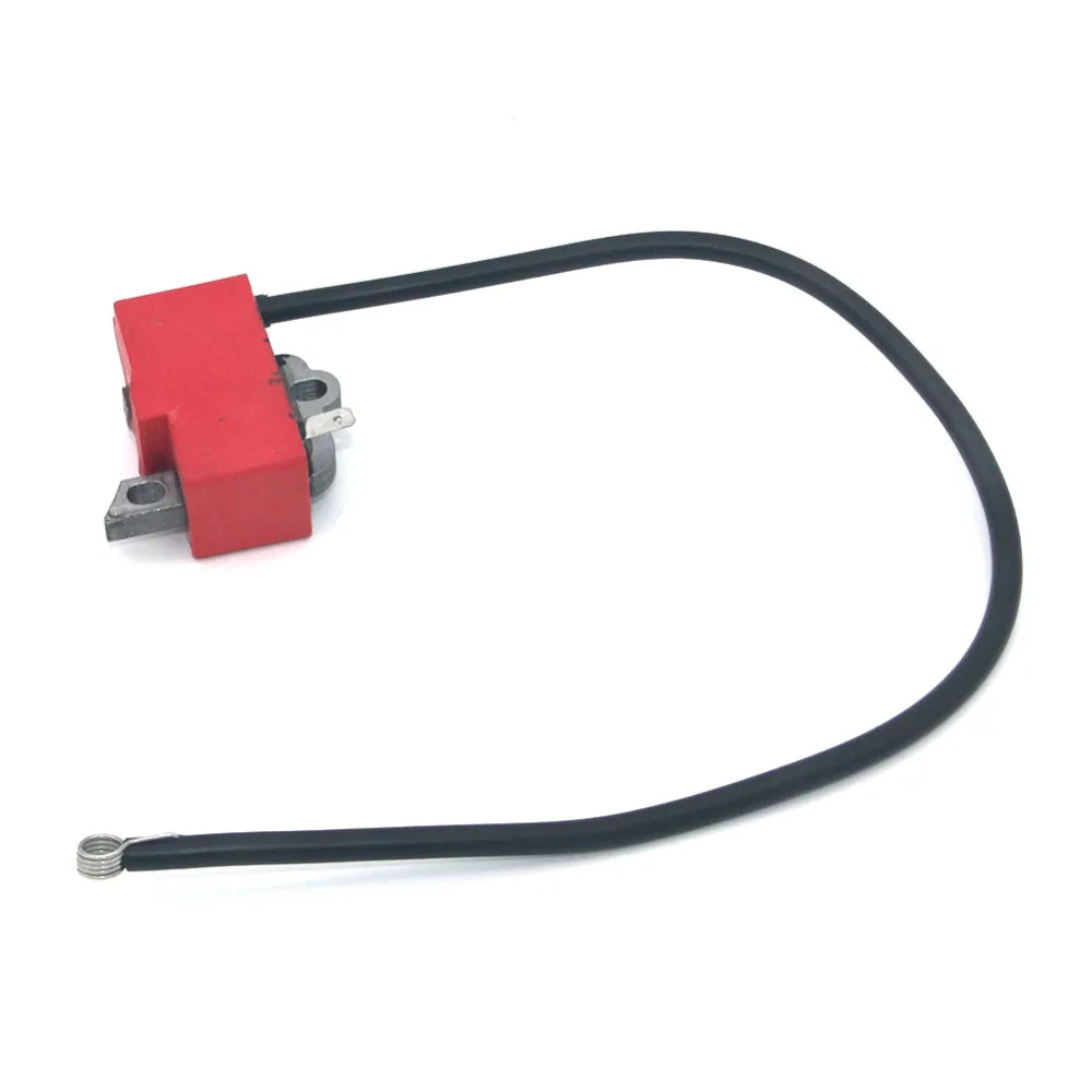
The Function of the Ignition Mechanism
The ignition system plays a crucial role in starting and maintaining the operation of equipment. It initiates the combustion process, which is essential for the engine to function effectively. Without this system, the engine would be unable to convert fuel into the mechanical energy required for performance.
The mechanism involves several interconnected components that work together to produce the necessary spark at the right time. The ignition process must be carefully synchronized with the engine’s internal movements to ensure smooth and efficient operation.
- Spark Creation: The system generates a spark to ignite the fuel mixture, allowing the engine to begin its cycle.
- Energy Transfer: Electrical energy is transmitted through a network of wires and coils, creating a high-voltage discharge.
- Timing: The ignition must occur at a precise moment during the engine’s cycle to maximize power and efficiency.
A well-functioning
Detailed Look at the Cutting Assembly
The cutting assembly is a key component in any tool designed for heavy-duty performance. Its precise engineering ensures efficient and accurate operation, providing users with the power to tackle demanding tasks. Understanding the specific elements involved in this assembly helps in maintaining optimal function and prolonging the lifespan of the device.
Blade and Its Housing
The blade is securely enclosed in a robust housing that shields the surrounding mechanisms while allowing smooth cutting action. This protective casing plays an essential role in reducing wear on the internal components and keeping the system in balance during operation.
Drive Mechanism
The drive mechanism is responsible for transferring energy from the power source to the blade. It works in harmony with the other components to deliver the necessary force for cutting through various materials. Regular inspection of this part ensures that the tool operates with maximum efficiency.
Air Filtration System and Maintenance
The air filtration mechanism is crucial for ensuring optimal engine performance and longevity. A well-maintained system helps prevent debris and dust from entering, thus minimizing wear and tear. Regular attention to this component ensures smooth operation and avoids costly repairs.
How the Filtration System Works
Air passes through a series of filters designed to capture particles of various sizes. These filters trap dust, dirt, and other contaminants before they reach sensitive internal components. Keeping this system in proper condition ensures clean airflow and efficient engine function.
Maintenance Steps

- Inspect the filters regularly for signs of dirt buildup or damage.
- Clean or replace filters according to the manufacturer’s recommendations or sooner if they appear clogged.
- Ensure proper sealing around the filter to prevent unfiltered air from bypassing the system.
- Check for any obstructions or debris in the air intake area.
By following these
Drive Belt Configuration and Replacement

Understanding the proper alignment and maintenance of the drive mechanism is crucial for ensuring smooth operation. The belt, acting as a connector between critical components, plays a key role in transmitting power. Over time, this part can wear out, necessitating timely replacement to maintain optimal performance.
Inspecting the Belt for Wear
Before replacing the belt, it’s essential to examine its condition. Look for signs of fraying, cracking, or stretching. These indicators suggest that the component is no longer functioning as it should. Regular inspections can help avoid sudden failures during operation.
Step-by-Step Replacement Process
Replacing the worn belt requires following a structured approach. First, ensure the machine is powered off and cooled down. Next, loosen the tension on the mechanism, carefully removing the old belt. Install the new component, making sure it aligns properly with the drive and tension
Examining the Cooling Mechanism

The cooling system plays a crucial role in maintaining the optimal temperature of a machine during operation. By efficiently regulating heat, it helps prevent overheating and ensures that the equipment runs smoothly, even under heavy loads. This process extends the life of the components by minimizing thermal stress and maintaining consistent performance over time.
One of the key elements in this setup is the airflow system, which directs cool air through specific channels to dissipate heat away from the core parts. The flow is carefully designed to optimize the cooling effect while minimizing any resistance or obstruction. Another critical factor is the material used for heat dissipation, which often includes metal fins or other heat-conducting components that draw excess warmth away from vital areas.
Additionally, the cooling mechanism may include safeguards such as thermal cutoffs, which ensure that the machine shuts down when temperatures exceed a certain threshold, preventing damage to essential parts. This comprehensive approach to temperature regulation ensures both safety and durability, even in demanding environments.
Lubrication Points for Optimal Performance
Ensuring proper lubrication is essential for maintaining the efficiency and longevity of any mechanical device. Identifying and regularly servicing critical areas can significantly enhance operational reliability and prevent premature wear.
Key lubrication points include:
- Moving Parts: Regularly lubricate all joints and pivot points to minimize friction and wear.
- Gear Mechanisms: Apply appropriate lubricant to gears to ensure smooth operation and reduce heat buildup.
- Chain and Belts: Maintain chains and belts with a suitable lubricant to prevent slippage and ensure efficient power transfer.
- Bearings: Inspect and grease bearings as necessary to prevent seizing and ensure quiet operation.
- Housing Seals: Lubricate seals to maintain proper function and prevent leaks from occurring.
Regular maintenance checks should be scheduled to ensure all lubrication points are serviced according to the manufacturer’s recommendations. This proactive approach not only enhances performance but also extends the life of the equipment.
How to Disassemble the Carburetor Unit

Disassembling the fuel mixing assembly is essential for maintenance and troubleshooting. Properly understanding the components and their arrangement will facilitate effective cleaning or replacement. Follow the steps below to achieve a successful disassembly.
- Prepare your workspace:
- Ensure you have adequate lighting.
- Gather necessary tools, including screwdrivers, wrenches, and a cleaning brush.
- Organize a container to hold small parts and screws.
- Remove the unit from the equipment:
- Disconnect any fuel lines carefully.
- Loosen any mounting screws or bolts.
- Gently lift the assembly away from the main body.
- Take apart the fuel mixing unit:
- Locate the screws securing the top cover.
- Remove the cover to access the internal components.
- Detach the diaphragm and other internal parts systematically.
- Inspect components:
- Examine each piece for wear or damage.
- Clean components using an appropriate solvent.
- Replace any faulty parts as necessary.
By following these guidelines, you can effectively disassemble the fuel mixing assembly, allowing for thorough maintenance and ensuring optimal performance of the equipment.
Handle and Control Setup Overview
This section provides a comprehensive examination of the handle and control configurations essential for optimal operation of the tool. Understanding the arrangement and functionality of these components is crucial for effective usage and maintenance.
Key Components
- Grip: Designed for user comfort and control.
- Throttle: Regulates power output and speed.
- Safety Switch: Prevents accidental activation.
- Adjustment Mechanism: Allows customization of the tool’s handling based on user preference.
Setup Instructions
- Begin by ensuring all components are clean and free from debris.
- Securely attach the grip to the designated area on the frame.
- Install the throttle mechanism, ensuring it is responsive and functions smoothly.
- Check the safety switch for proper alignment and operation.
- Make any necessary adjustments to the configuration to suit individual handling requirements.
Tips for Replacing Worn-Out Parts
Maintaining equipment in peak condition is essential for optimal performance and longevity. When components begin to show signs of wear, timely replacement can prevent further damage and ensure efficient operation. This section provides valuable insights into effectively swapping out exhausted elements to keep your machinery running smoothly.
Assessing the Condition
Before proceeding with any replacements, it is crucial to evaluate the state of the various components. Regular inspections can help identify which parts require attention. Look for signs of deterioration such as cracks, corrosion, or excessive wear. Understanding the condition of each component will guide you in prioritizing replacements and planning your maintenance schedule.
Replacement Process
When it comes time to replace a worn item, following a systematic approach will enhance efficiency and accuracy. Below are key steps to consider during the replacement process:
Step Description 1 Gather the necessary tools and new components before starting the replacement to ensure a smooth process. 2 Follow the manufacturer’s instructions or guidelines to safely detach the worn item without damaging surrounding areas. 3 Install the new component, ensuring it fits securely and correctly to avoid future issues. 4 Conduct a thorough check of the equipment post-installation to ensure everything is functioning as intended. By adhering to these guidelines, you can effectively replace deteriorated elements, enhancing the reliability and efficiency of your equipment.
Maintaining the Makita EK6101 for Longevity
Proper upkeep of equipment is essential to ensure its long-lasting performance and reliability. Regular maintenance not only enhances functionality but also minimizes the likelihood of unexpected breakdowns. By following a systematic approach to care, users can extend the lifespan of their tools and maintain peak performance over time.
To achieve optimal results, it is crucial to adhere to the manufacturer’s guidelines while also implementing a routine maintenance schedule. This involves inspecting key components, cleaning regularly, and replacing worn parts when necessary. Below is a table outlining essential maintenance tasks and their recommended frequencies.
Maintenance Task Frequency Inspect and clean air filter Every 10 hours of use Check fuel lines for leaks Every use Sharpen cutting blades As needed Inspect spark plug Every 20 hours of use Change oil Every 50 hours of use Inspect overall condition and connections Before each use By diligently following these maintenance practices, users can enhance the efficiency and durability of their equipment, ensuring it remains a reliable companion for various tasks over the years.
Exploring the Fuel System Layout
The arrangement of components responsible for delivering fuel is essential for the smooth operation of any equipment. Understanding how these elements interact ensures proper maintenance and troubleshooting, especially when optimizing performance and prolonging the machine’s lifespan. This section will provide a detailed look at the essential connections and flow paths involved.
Key Components and Their Roles