| Rivets |
The rivets hold the chain’s links together, maintaining the structure’s strength and flexibility under load. |
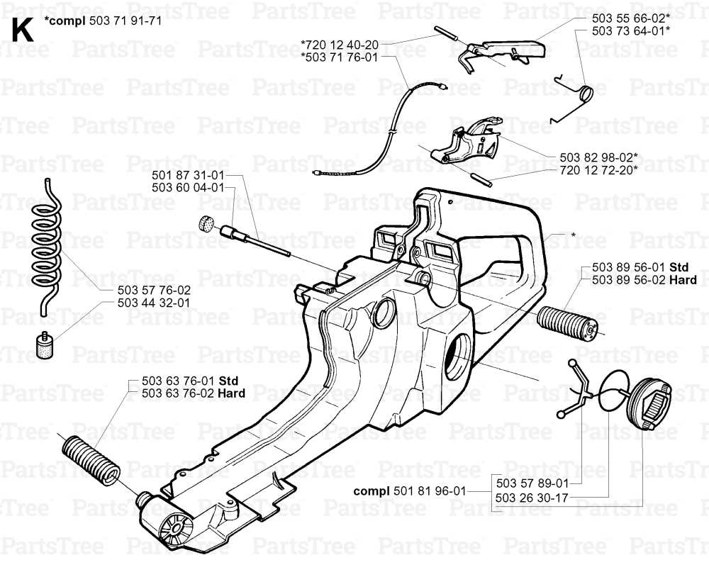
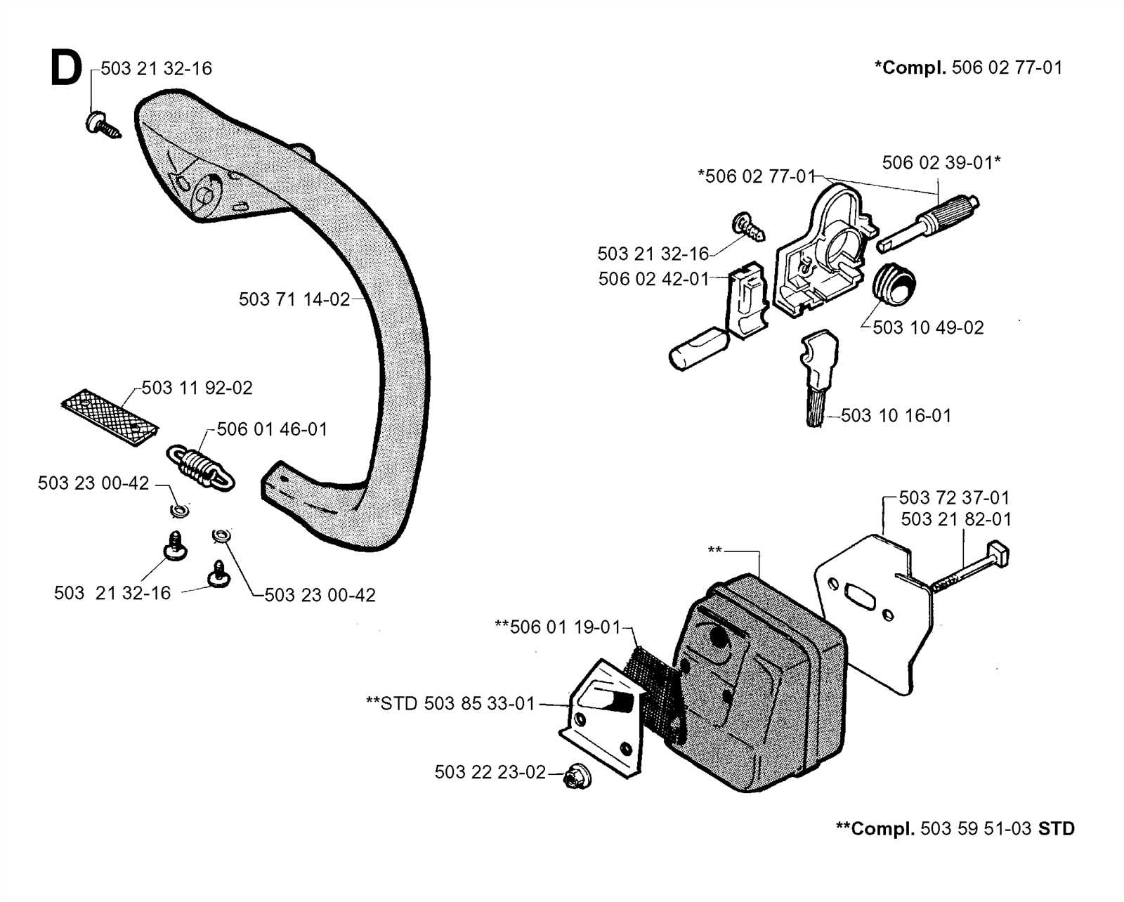
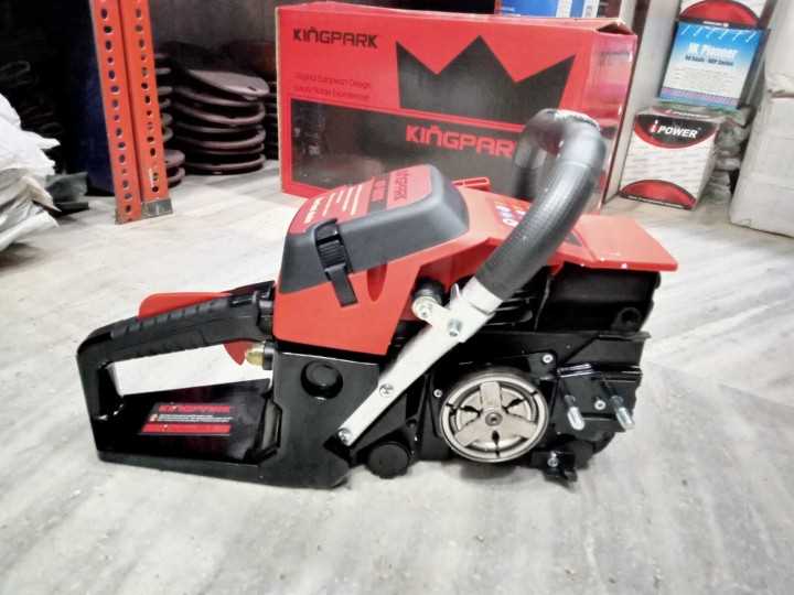
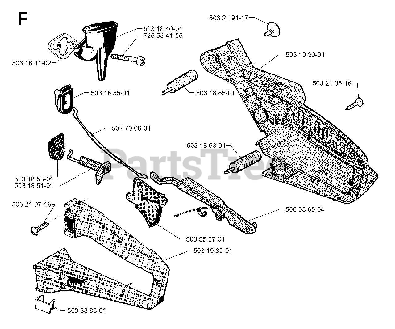
Handle and Grip Construction
The handle and grip of a cutting tool are vital for user comfort and control during operation. Their design directly influences the effectiveness and safety of handling the device. A well-constructed grip ensures that the operator can maneuver the tool with precision and ease, minimizing fatigue during prolonged use.
Key elements of the handle and grip include:
- Material: Various materials are utilized, such as plastic, rubber, or composite, each offering unique benefits regarding durability and grip.
- Ergonomics: The shape and contour of the grip are designed to fit comfortably in the hand, reducing strain and enhancing control.
- Texturing: Surface patterns and textures are incorporated to improve traction, ensuring a firm hold even in adverse conditions.
In addition to these aspects, the assembly of the handle involves:
- Securing the grip components to the main structure.
- Integrating protective features to shield the operator’s hands from vibrations.
- Ensuring that the trigger and control mechanisms are easily accessible without compromising grip stability.
Understanding these components is crucial for anyone looking to maintain or enhance their tool’s usability, ensuring a reliable and safe experience during operation.
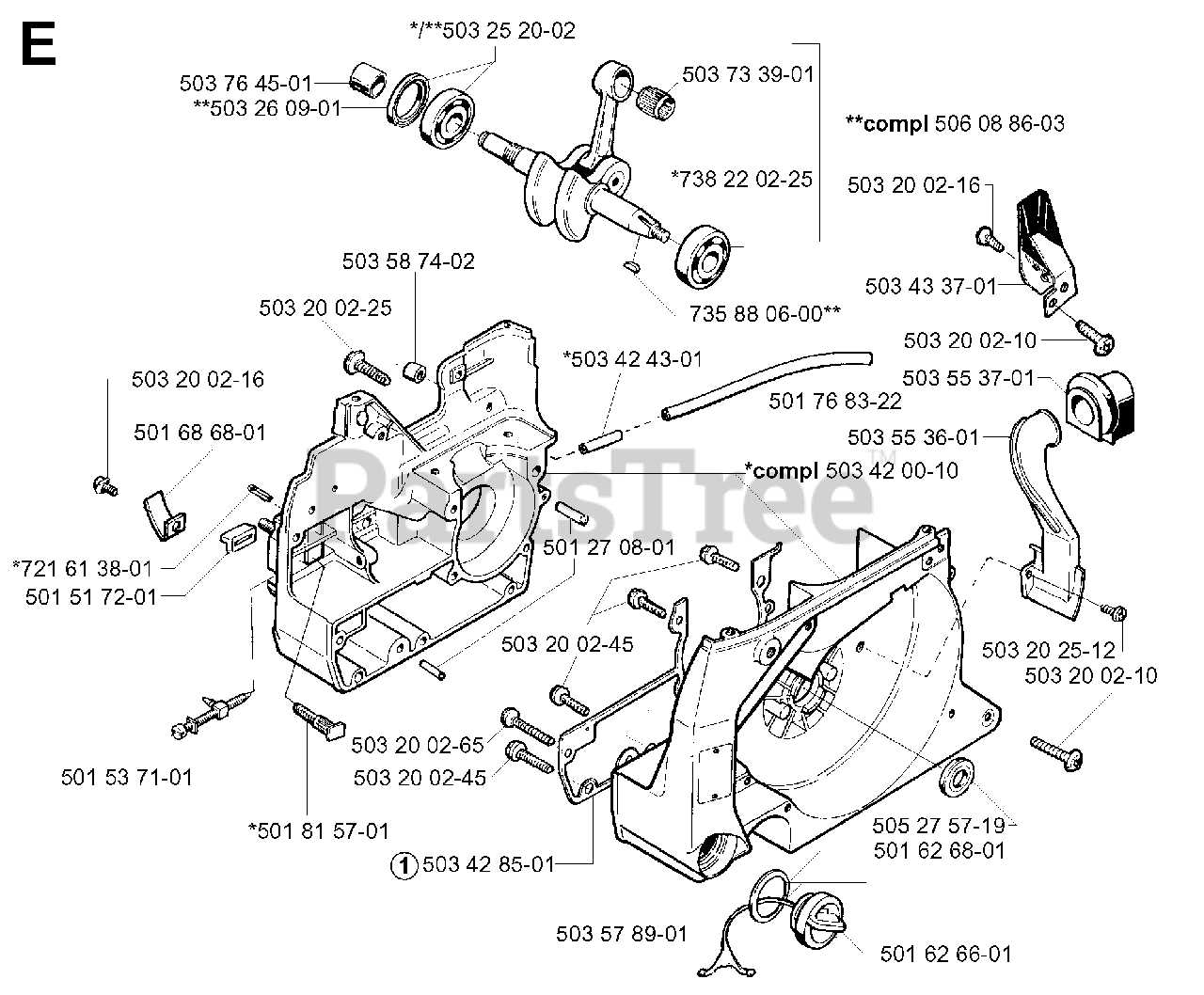
Fuel System and Tank Layout
The fuel system is a crucial component of any power tool, ensuring that the engine receives the necessary energy for optimal performance. This system comprises various elements that work in harmony to store, transport, and deliver fuel efficiently. Understanding the arrangement and function of these components can enhance maintenance practices and improve overall functionality.
At the core of the fuel assembly lies the tank, which serves as the reservoir for the energy source. Its design often features a cap for easy refueling and ventilation to maintain pressure balance. Connected to the tank are fuel lines that facilitate the flow of liquid to the engine. These lines are typically made from durable materials to withstand various environmental conditions and the corrosive nature of fuels.
The assembly may also include filters to ensure that impurities do not enter the engine, protecting it from potential damage. In some configurations, a primer bulb is present, allowing users to manually draw fuel into the system before starting the engine. This feature enhances reliability, particularly after prolonged periods of inactivity.
Lastly, the layout of the entire system is designed for accessibility and efficiency, allowing for straightforward maintenance and quick troubleshooting. Familiarity with this configuration can significantly aid users in achieving optimal operation and extending the lifespan of their equipment.
Exhaust and Muffler Configuration
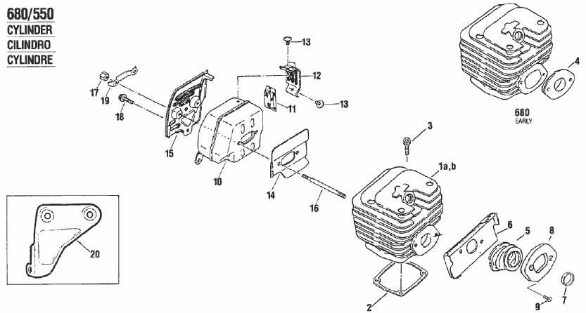
The arrangement of the exhaust system plays a crucial role in the overall performance and efficiency of power equipment. Properly configured exhaust and muffler components help manage engine noise while ensuring optimal operation by directing exhaust gases away from the engine effectively. Understanding the intricacies of these components can significantly enhance functionality and prolong the lifespan of the equipment.
Key Functions of Exhaust Components
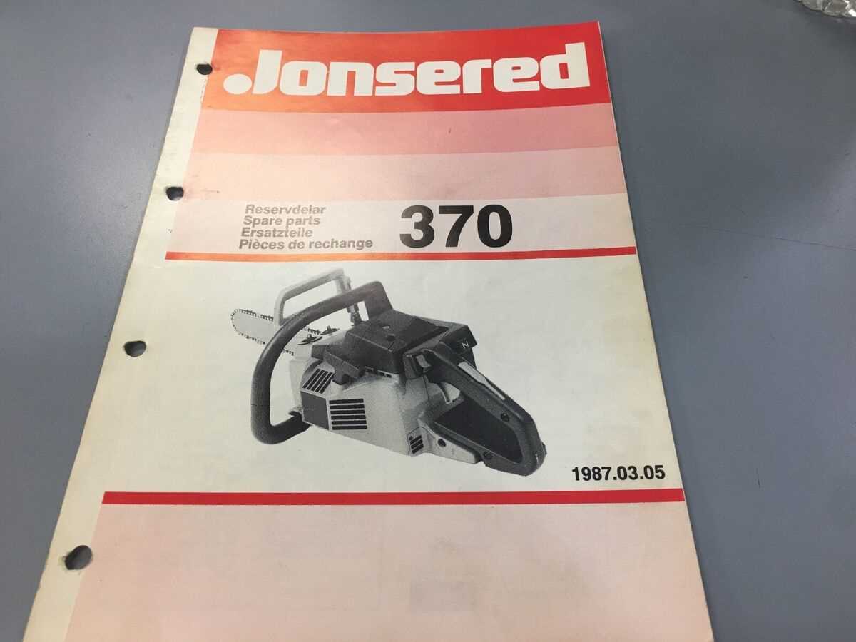
The exhaust system serves several essential functions. Primarily, it facilitates the safe expulsion of combustion gases from the engine, preventing potential back pressure that could hinder performance. Additionally, the muffler plays a vital role in reducing noise levels, making the equipment more user-friendly. The design of these components can vary, influencing factors such as noise reduction, gas flow efficiency, and overall power output.
Common Configuration Features
Configuration features can differ based on design requirements and intended usage. Materials used in manufacturing these components are chosen for durability and resistance to heat. Furthermore, mounting angles and pipe diameters can impact exhaust flow rates, affecting how efficiently gases exit the system. Attention to these details ensures that the equipment operates smoothly while maintaining compliance with environmental noise regulations.
Air Filter Placement and Maintenance
The proper positioning and care of the air filtration component are crucial for ensuring optimal performance and longevity of your outdoor equipment. This section will guide you through the significance of maintaining clean air pathways and how to effectively manage this vital aspect of your machinery.
Importance of Air Filter Location
Correctly placing the filtration unit is essential for preventing dust and debris from entering the engine. A well-positioned filter ensures that only clean air circulates, which helps in maintaining efficient combustion and overall functionality. Regularly checking the filter’s placement can prevent potential damage and costly repairs.
Maintenance Tips for Optimal Performance
Routine maintenance of the air filtration system is necessary for sustained operation. It is advisable to clean or replace the filter as per the manufacturer’s guidelines, particularly in dusty environments. Keeping the filter free from clogs will enhance airflow and improve fuel efficiency, ensuring that your equipment runs smoothly and effectively.
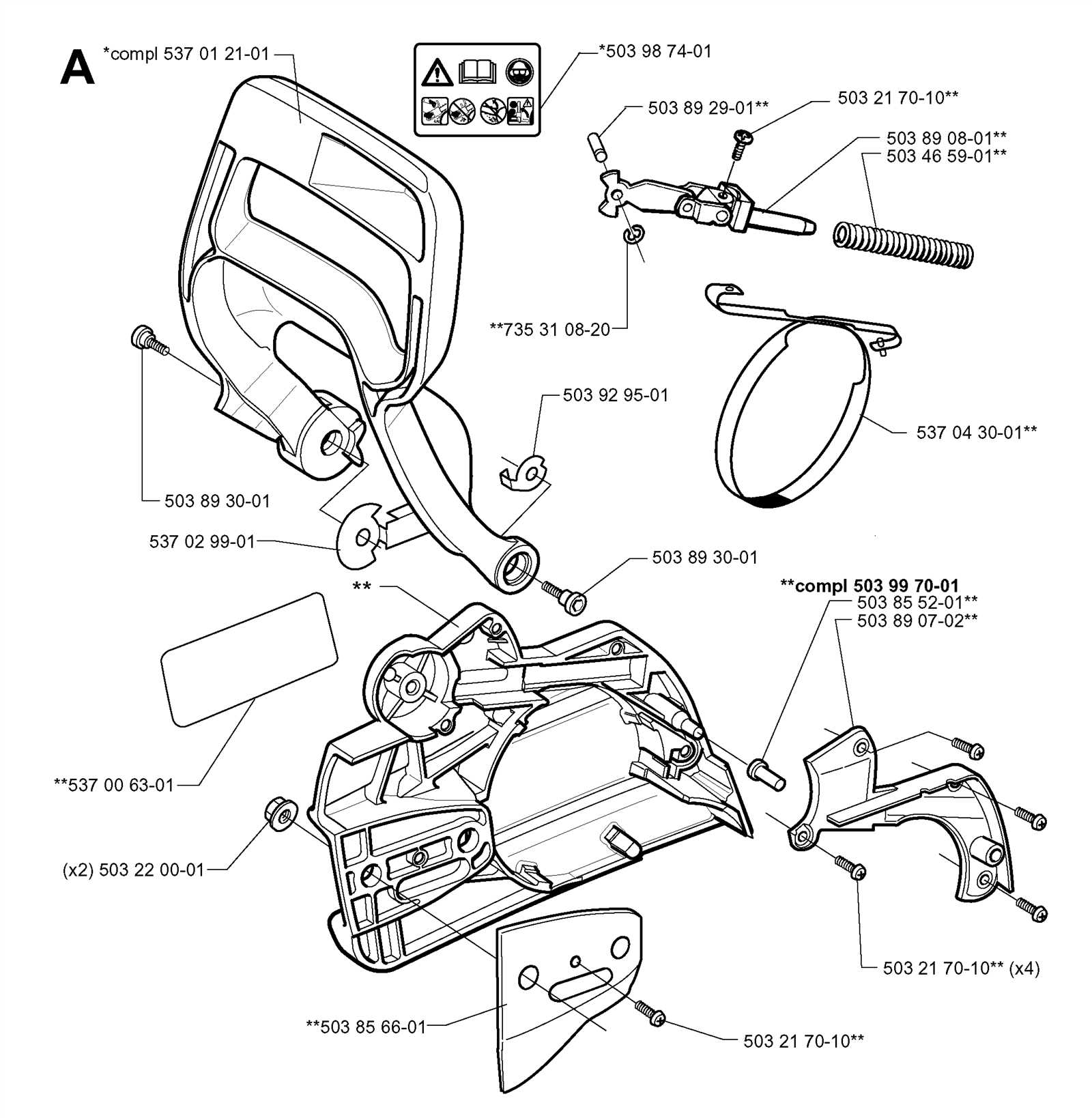
Safety Features and Mechanisms
Effective safety mechanisms are essential in ensuring the secure operation of any power tool. These features are designed to minimize the risk of accidents and injuries during use, providing peace of mind for operators. Understanding these safety attributes is crucial for both novice and experienced users alike.
One of the primary safety elements includes the activation switch, which allows for immediate shutdown when necessary. This mechanism helps prevent unintended operation and is critical in emergency situations. Additionally, anti-vibration systems play a significant role by reducing user fatigue, enabling better control over the device.
Another vital component is the chain brake, which halts the chain’s movement rapidly in case of kickback. This feature is instrumental in protecting the user from potential harm, especially when handling powerful equipment. Furthermore, protective guards are installed to shield the operator from debris and accidental contact with moving parts.
Regular maintenance and inspections of these safety features are necessary to ensure their effectiveness. By prioritizing these mechanisms, users can enhance their safety while achieving optimal performance from their tools.
Ignition System Parts Identification
The ignition assembly is a crucial component in ensuring the effective operation of small engines. Understanding the various elements that make up this system can significantly enhance troubleshooting and maintenance efforts. This section focuses on the identification of essential components that contribute to the ignition process, providing clarity on their functions and relevance.
Ignition Coil: This device generates high voltage from the low voltage supply, creating the spark necessary for combustion. Its proper functioning is vital for engine start-up and overall performance.
Spark Plug: Acting as a bridge for electricity, the spark plug ignites the air-fuel mixture in the combustion chamber. Identifying its condition can indicate engine health, as wear can lead to misfiring or hard starting.
Flywheel: This rotating component houses magnets that interact with the ignition coil to produce a spark. A malfunctioning flywheel can disrupt the timing of the ignition, causing performance issues.
Contact Points: These are part of the mechanical ignition system, opening and closing to control the flow of electricity. Ensuring they are clean and correctly adjusted can improve ignition efficiency.
Trigger Module: This electronic component detects the position of the flywheel and signals the ignition coil to fire. Proper identification and testing of this module are essential for diagnosing electronic ignition systems.
By familiarizing oneself with these essential components, one can ensure the reliable operation of the ignition assembly, leading to improved efficiency and performance of the engine.
Lubrication System and Oil Path
The efficiency and longevity of power equipment significantly depend on the proper functioning of its lubrication mechanism. This system plays a crucial role in reducing friction and wear between moving components, ensuring smooth operation and optimal performance.
Components of the Lubrication Mechanism
- Oil reservoir: Holds the lubrication fluid.
- Pump: Distributes oil to necessary parts.
- Oil lines: Channels that transport the lubricant.
- Filters: Remove impurities from the oil.
Oil Path and Flow
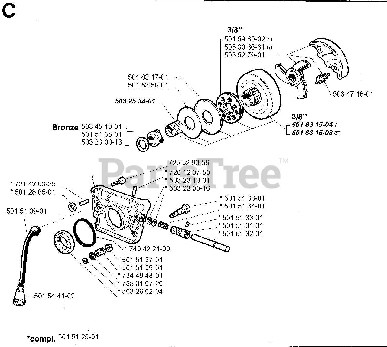
The flow of lubricant is essential for maintaining the effectiveness of the system. The process typically involves:
- Oil is drawn from the reservoir by the pump.
- The pump sends the oil through a series of channels.
- Lubricant reaches critical areas where it forms a protective layer.
- Excess oil is returned to the reservoir for recycling.
Throttle and Control Layout
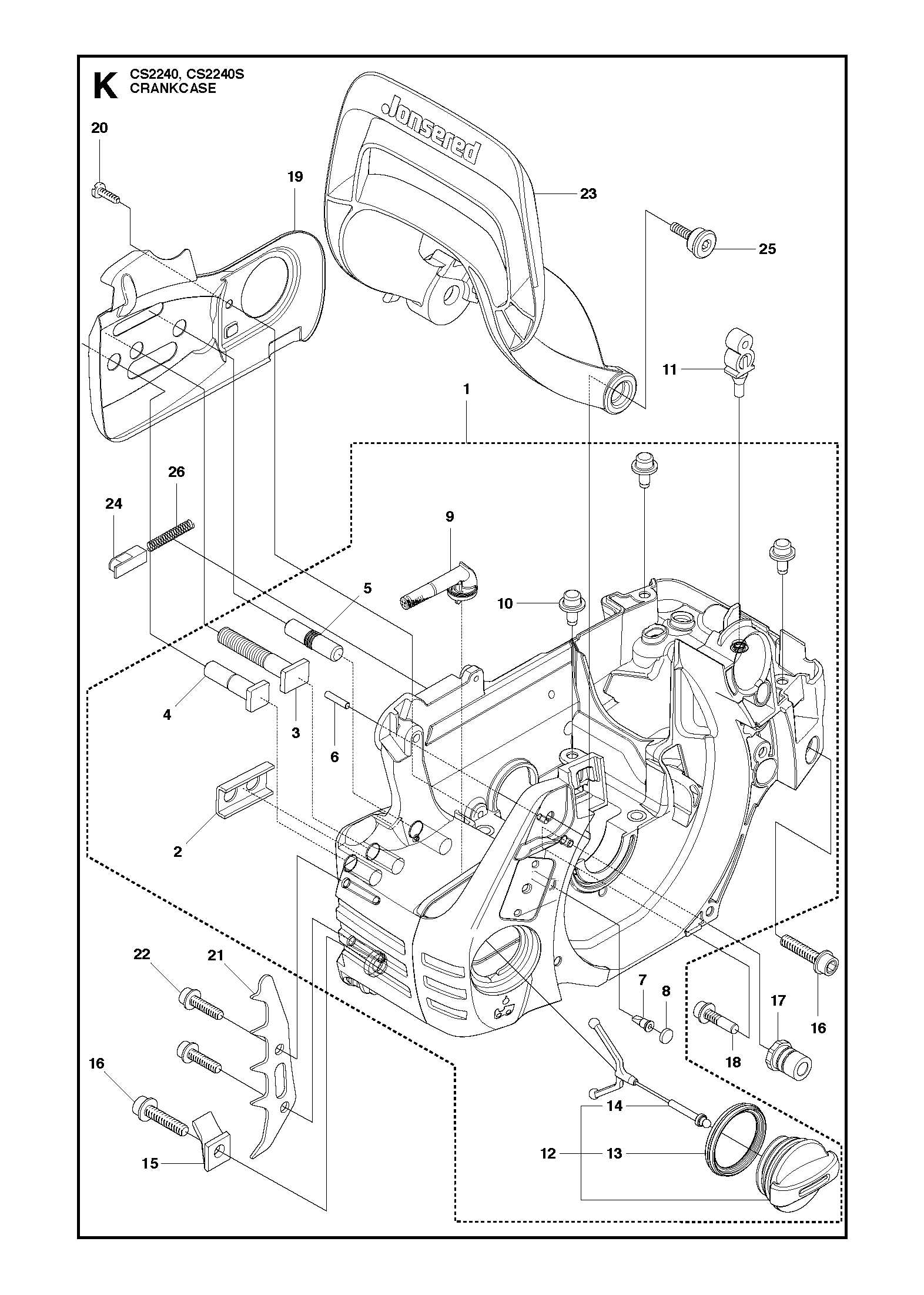
The configuration of control mechanisms plays a crucial role in the effective operation of outdoor power equipment. Understanding how these components are arranged can significantly enhance user experience and performance. This section explores the various elements that comprise the throttle and control system, emphasizing their functions and interactions.
Key Components
- Throttle Lever: This element allows the operator to adjust the power output and manage the engine speed.
- Choke Control: Used to enrich the fuel mixture during startup, facilitating easier ignition in cold conditions.
- Stop Switch: A critical safety feature that enables the user to quickly shut down the engine when necessary.
- Trigger Mechanism: Engages the throttle lever and modulates the engine’s power according to the user’s input.
Functional Interactions
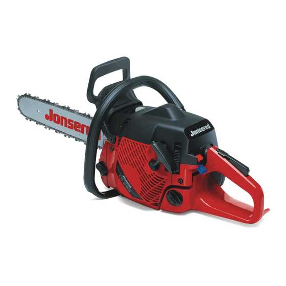
Each component is interconnected, contributing to the overall functionality of the system. The throttle lever directly influences engine speed, while the choke control modifies the air-fuel mixture, ensuring optimal combustion. The stop switch provides an essential safety net, allowing immediate shutdown. The seamless operation of these controls is vital for maintaining efficiency and safety.
