
Understanding the configuration and functionality of various mechanical elements is crucial for ensuring the smooth operation of any equipment. This section delves into the intricate details of these elements, offering a clear and concise look into how each piece plays its role in maintaining efficiency and reliability.
The guide aims to provide valuable insights into the structure and placement of essential elements within the system. By examining these components closely, you will gain a deeper comprehension of their interdependence and how to address potential issues effectively.
Proper maintenance and accurate identification of mechanical parts are key to extending the lifespan of your machinery. With the information provided, you will be equipped to handle routine checks, repairs, and replacements with greater confidence and precision.
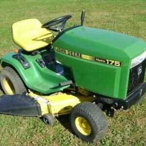
John Deere 175 Hydro Parts Diagram
Understanding the layout and configuration of components in this lawn tractor model is essential for maintenance and repair. Each element plays a crucial role in ensuring smooth operation and longevity of the machine, whether it’s related to engine functionality, drive mechanisms, or auxiliary systems.
Key System Components
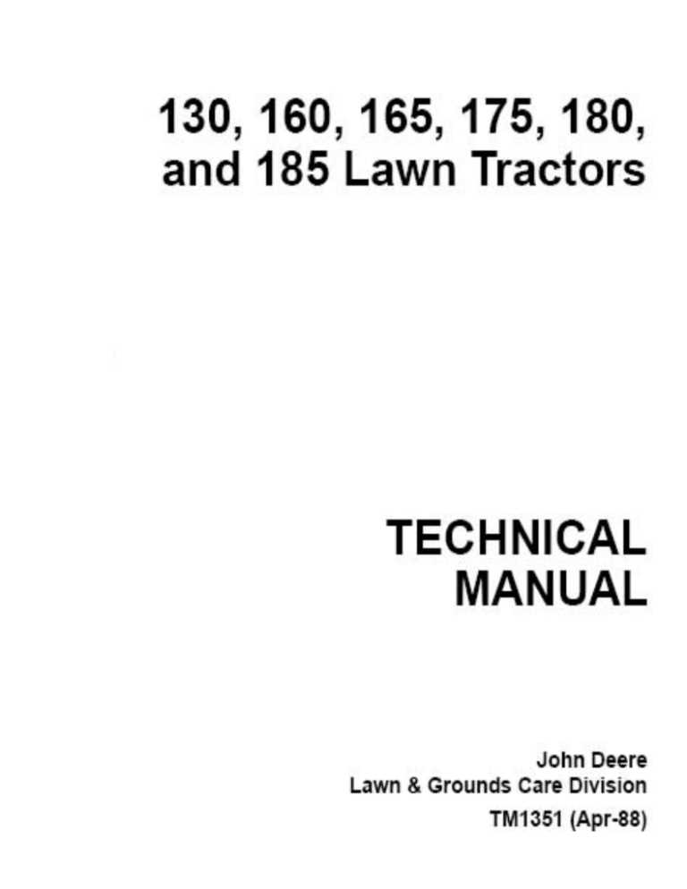
The primary systems include the engine, transmission, and cutting mechanism, each made up of several integral parts working together. Proper identification of each component ensures accurate repairs and replacements when needed.
Detailed Configuration
Each section of the machine follows a specific layout, designed for optimal performance. By examining the configuration closely, one can understand the role of individual modules and how they connect within the entire framework.
Understanding the Hydrostatic Drive Components
The hydrostatic drive system plays a crucial role in transferring power efficiently within machinery, ensuring smooth operation and control. This section delves into the essential elements that make up this system, focusing on how they work together to achieve seamless motion and torque distribution. Understanding these elements is key to maintaining optimal performance and prolonging the equipment’s life.
Main Components of the System

- Pump: Converts mechanical power into hydraulic energy, facilitating fluid movement throughout the system.
- Motor: Receives hydraulic fluid and converts it back into mechanical energy to drive the wheels or tracks.
- Reservoir: Stores and supplies hydraulic fluid, keeping the system pressurized and operating smoothly.
- Filters:
Essential Engine Parts for John Deere 175
Understanding the key elements that keep a garden tractor’s engine running smoothly is crucial for efficient performance and longevity. Each component plays a specific role in ensuring the machine operates without interruptions, whether it’s for mowing or other yard tasks. Familiarity with these core components will help maintain the engine’s reliability and power.
Component Function Carburetor Mixes air and fuel in the right ratio for combustion. Ignition Coil Generates the high voltage needed to ignite the fuel mixture. Detailed Overview of Steering Mechanism
The steering system is an essential component that allows precise control and direction of a vehicle. It is designed to provide a smooth and responsive driving experience, ensuring that the operator can easily maneuver the equipment in various environments. Understanding how the key elements work together offers valuable insights into maintaining optimal performance.
Key Components and Their Functionality
The primary elements of the steering system include a wheel, linkages, and gear systems. The wheel, connected through a series of rods, transfers the operator’s input into the control of the vehicle’s movement. The gear system amplifies this input, allowing the front tires to turn smoothly and efficiently. Proper maintenance of these parts ensures long-term reliability and precise handling.
Common Issues and Maintenance Tips
Analyzing the Electrical System Configuration
The electrical system plays a crucial role in the efficient functioning of machinery. By understanding the arrangement and flow of current, users can identify and address any potential issues. This section explores the key components involved in the electrical setup, focusing on how power is distributed and controlled within the equipment.
Main Components and Connections
The electrical system typically consists of several core components, including the power source, wiring harnesses, and control units. Proper configuration ensures that the electrical flow is both stable and reliable, minimizing the risk of malfunctions. Each connection point must be carefully analyzed for continuity and safety.
Power Distribution Layout
Component Function Power Source Exploring the Fuel Delivery Components
The efficiency of any engine relies heavily on its ability to manage the flow of fuel. Understanding the various elements involved in this process is crucial for optimal performance. This section delves into the essential components that ensure a steady and reliable supply of fuel to the engine, ultimately influencing its functionality and longevity.
Key Elements of Fuel Delivery
Fuel delivery systems consist of several critical components, each playing a vital role in ensuring proper operation. The fuel tank serves as the initial storage unit, while the fuel pump is responsible for transporting the liquid to the engine. Additionally, filters are essential for removing impurities, ensuring that only clean fuel reaches the combustion chamber.
Importance of Maintenance
Regular inspection and maintenance of the fuel delivery system are vital to prevent issues such as clogging or leaks. Neglecting these components can lead to performance degradation, reduced efficiency, and potentially costly repairs. Understanding how to care for these elements is essential for any operator seeking to maximize the lifespan of their machinery.
Brake System Parts and Maintenance Tips
The braking mechanism of any machinery plays a crucial role in ensuring safety and optimal performance. Regular upkeep and understanding of its components can significantly enhance the longevity and efficiency of the entire system. This section will explore essential elements of the braking assembly and provide valuable maintenance advice.
Key components of the braking system include the following:
Component Description Brake Pads Friction materials that press against the rotor to slow down the vehicle. Rotors Circular metal discs that the brake pads clamp onto to create friction. Calipers Housings that hold the brake pads and apply pressure to them. Brake Lines Hoses that carry hydraulic fluid from the master cylinder to the calipers. Master Cylinder Component that converts mechanical force into hydraulic pressure. To ensure optimal functionality, it is essential to perform regular inspections and maintenance of these components. Here are some helpful tips:
- Check brake fluid levels regularly and replace if necessary.
- Inspect brake pads for wear and replace them when they become too thin.
- Examine rotors for any signs of warping or scoring.
- Bleed the brake lines to remove air bubbles and ensure effective braking performance.
- Keep the calipers clean and free of debris to prevent sticking.
Identifying Key Transmission Components
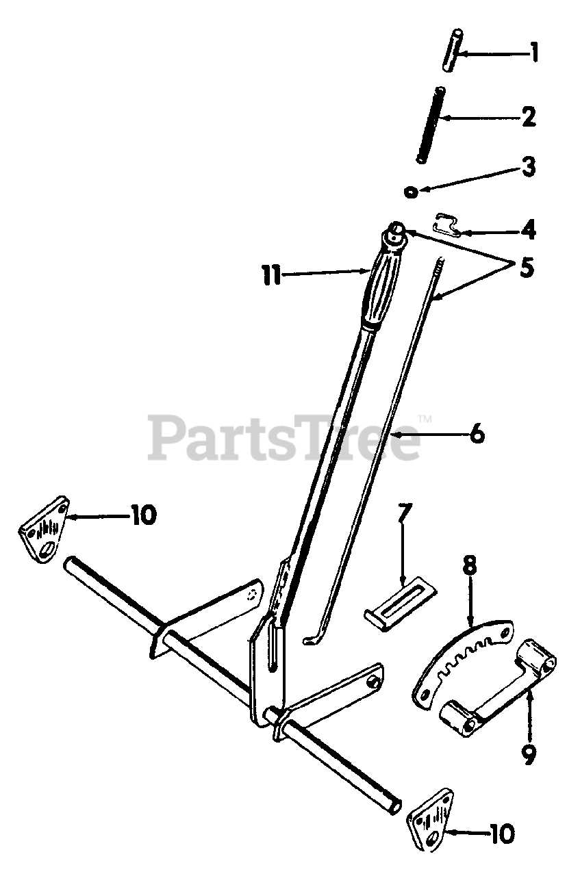
The transmission system is crucial for the effective operation of machinery, ensuring that power is transferred efficiently from the engine to the wheels. Understanding its essential components helps in maintaining optimal performance and longevity.
Key elements of the transmission assembly include:
- Gearbox: Responsible for adjusting the torque and speed, allowing for better control of the equipment.
- Torque Converter: Enhances the power delivery by converting engine power into hydraulic energy.
- Driveshaft: Transmits the rotational force from the gearbox to the wheels.
- Clutch: Engages and disengages the engine from the transmission, facilitating smoother transitions.
- Transmission Fluid: Provides lubrication and cooling, ensuring the system operates efficiently.
Familiarity with these components aids in troubleshooting and repair, ultimately enhancing the functionality of the machinery.
Cooling System Diagram for John Deere 175
The cooling system in machinery plays a crucial role in maintaining optimal operating temperatures. It ensures that the engine does not overheat, thereby enhancing performance and longevity. Understanding the components and flow within this system is essential for effective maintenance and troubleshooting.
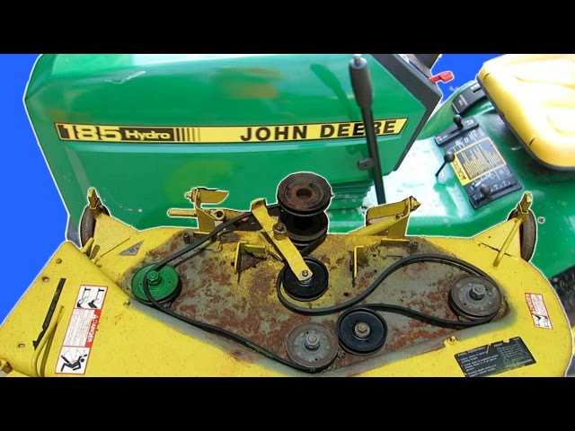
This system typically consists of a radiator, water pump, thermostat, and various hoses that facilitate coolant circulation. The radiator dissipates heat absorbed by the coolant, while the pump circulates the fluid through the engine and back. Additionally, the thermostat regulates the coolant flow based on temperature, ensuring efficient operation. Regular inspection of these components can prevent overheating issues and ensure the smooth functioning of the equipment.
Troubleshooting Common Mechanical Issues
Addressing frequent mechanical challenges can significantly enhance the performance and longevity of equipment. Understanding potential problems and their solutions can prevent unnecessary downtime and costly repairs. Below are some common issues and effective troubleshooting strategies.
-
Unresponsive Controls:
If the controls are not responding as expected, consider the following steps:
- Check the battery voltage to ensure it is adequately charged.
- Inspect the wiring and connections for any signs of wear or damage.
- Examine the control module for faults or error codes.
-
Inconsistent Power Delivery:
If the machinery is experiencing power issues, try these troubleshooting techniques:
- Verify the fuel supply and filter for clogs or blockages.
- Inspect the fuel lines for leaks or deterioration.
- Assess the ignition system components for proper function.
-
Overheating:
Overheating can
Belts and Pulleys: Essential Information
In the realm of mechanical systems, the functionality of drive components is paramount for optimal operation. These elements work in unison to transfer power efficiently, ensuring that machines perform their designated tasks smoothly and reliably. Understanding the significance of these components is crucial for maintenance and troubleshooting.
Importance of Drive Components
Drive components, such as belts and pulleys, play a vital role in transmitting motion from one part of the machinery to another. Belts are flexible loops that connect two or more rotating shafts, while pulleys serve as wheels that guide the belts. This combination allows for the efficient transfer of energy and movement, reducing wear and enhancing performance.
Maintenance Tips
To ensure longevity and efficiency, regular inspection of these components is necessary. Look for signs of wear, such as cracks or fraying on belts, and ensure that pulleys are properly aligned. Additionally, lubrication of moving parts can prevent unnecessary friction, prolonging the life of the entire system.
Guide to Front and Rear Axle Parts
The functionality of a vehicle greatly relies on its wheel assembly, which encompasses the essential components of both the front and rear axle. These critical elements work together to ensure stability, maneuverability, and overall performance during operation. Understanding these components is vital for maintenance and troubleshooting.
Front Axle Components: The front axle assembly primarily includes elements such as the steering knuckles, spindles, and bearings. These parts facilitate turning and support the weight of the machine, allowing for enhanced control and responsiveness on various terrains.
Rear Axle Components: The rear axle plays a crucial role in providing traction and distributing power to the wheels. Key components here include the differential, axle shafts, and housing. Each element is designed to withstand significant stress while ensuring smooth operation and efficiency.
Regular inspection and maintenance of these assemblies can prevent wear and prolong the lifespan of the equipment. Knowledge of the structure and function of these vital components is essential for any operator or technician.