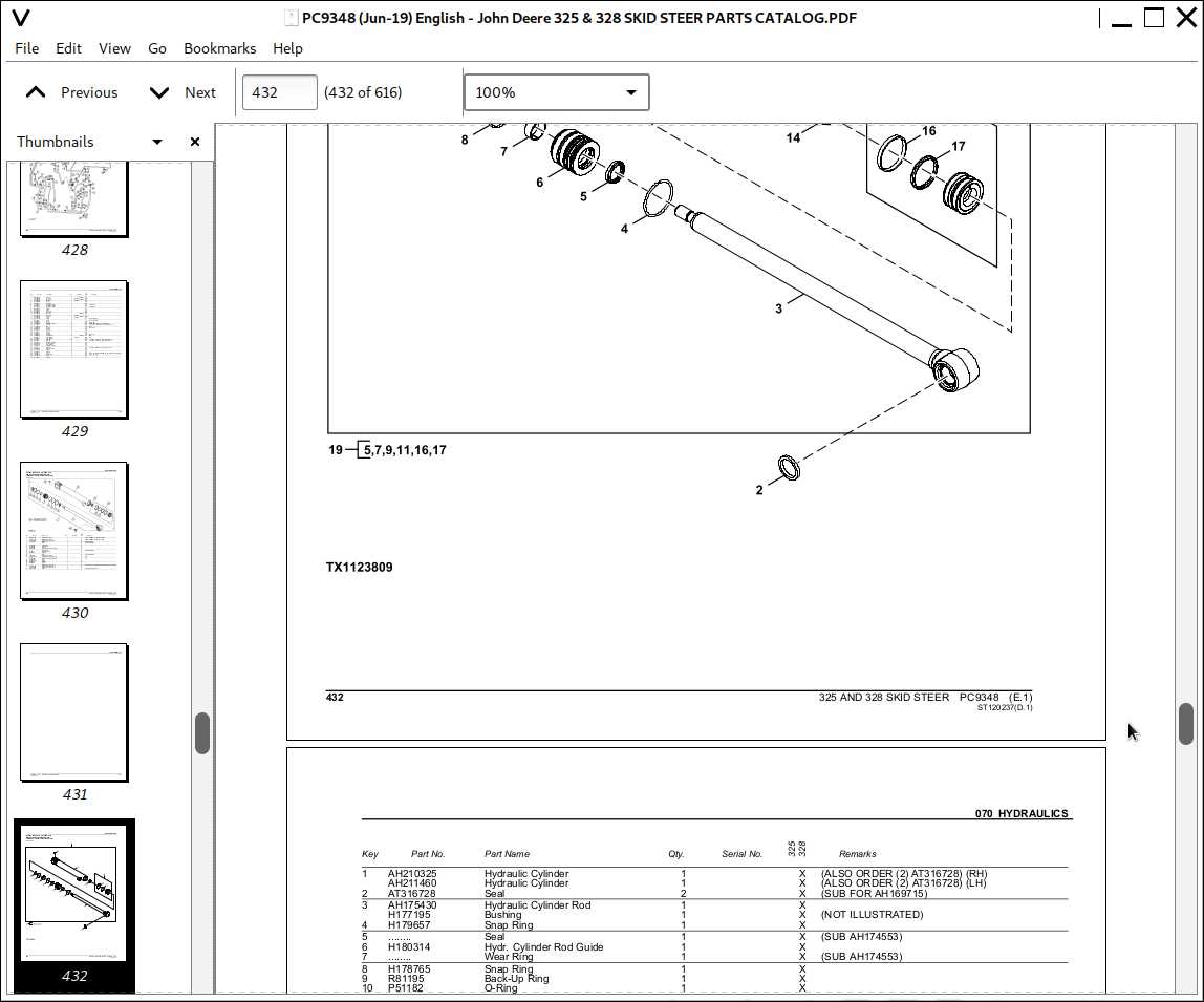
Understanding the internal structure of machinery is essential for ensuring its longevity and smooth operation. Detailed visualizations and schematics can provide a clear insight into how different elements work together, enabling better diagnostics and repairs when needed. This guide aims to offer a systematic approach to identifying various elements, making it easier for technicians and users alike to perform necessary maintenance.
Efficient machine management begins with a deep comprehension of how the intricate components are aligned and interact. By familiarizing yourself with the layout of each section, you can avoid potential problems and ensure optimal performance. This approach empowers you with the knowledge needed to address issues before they escalate into costly repairs or replacements.
With an emphasis on reliable equipment upkeep, this guide helps streamline your workflow. Whether dealing with engine complexities or smaller systems, knowing where each element fits allows for targeted troubleshooting and quick resolutions. Dive into the following sections to enhance your understanding of critical machinery structures
Key Components Overview
Understanding the various mechanisms that drive the efficient operation of heavy equipment is essential for maintenance and troubleshooting. Each machine relies on several interconnected systems that work in harmony to deliver performance and durability in different environments.
The core mechanisms include engine assembly, which powers the machine, and the hydraulic system, enabling fluid motion and control. Additionally, the transmission is crucial for adapting to various terrains, while the electrical network ensures all components communicate efficiently. Regular checks of these elements can help prevent downtime and ensure the longevity of the equipment.
Engine System Breakdown
The heart of any machine lies within its power unit. This section provides a detailed look into the various components responsible for generating and managing energy output, ensuring smooth operation and longevity. Understanding these elements can significantly aid in maintaining performance and identifying potential issues before they escalate.
Main Components
- Fuel Delivery Mechanism – Ensures consistent and efficient fuel supply to the combustion chamber.
- Cooling Circuit – Prevents overheating by circulating coolant to regulate temperature during operation.
- Ignition Control – Responsible for initiating combustion by providing the necessary spark at precise intervals.
- Exhaust System – Safely removes waste gases from the power unit, ensuring optimal emission levels and efficiency.
Maintenance Tips
- Regularly inspect the fuel lines for leaks or blockages.
- Ensure the cooling circuit is free from debris to avoid overheating.
- Check ignition components periodically to maintain firing
Understanding the Transmission Mechanism
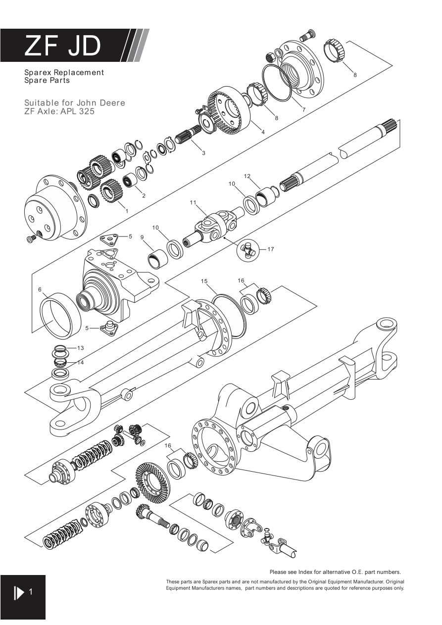
In order to grasp the operation of the vehicle’s propulsion system, it is important to focus on how the energy from the engine is transferred to the wheels. The transmission plays a key role in this process by adjusting power output, ensuring the machine functions smoothly in varying conditions. This system governs speed regulation and torque distribution, making it essential for consistent performance.
Power Flow and Gear Engagement
The mechanism works by shifting gears, which determines the speed and force applied. When lower gears are engaged, more torque is produced to handle heavier tasks, while higher gears provide greater speed for lighter workloads. Proper synchronization between the engine and the transmission allows for seamless transitions between different modes of operation.
Maintenance and Efficiency
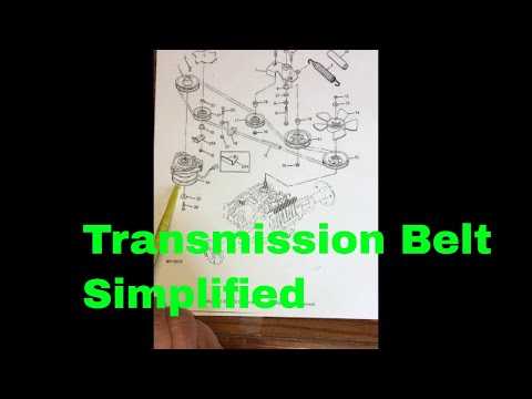
Ensuring that the transmission is well-maintained is critical for preventing breakdowns and extending the life of the machine. Regular inspections and fluid changes are recommended to keep the system running efficiently. Attention to small issues can prevent costly repairs and enhance the overall reliability of the equipment.
Hydraulic Circuit Layout
The hydraulic system is designed to provide efficient control over various components through the use of fluid pressure. This setup ensures smooth operation and precise movement, allowing machinery to perform demanding tasks with consistency. Understanding the flow of hydraulic fluid within the system is key to diagnosing performance issues and maintaining optimal functionality.
Main Fluid Pathways
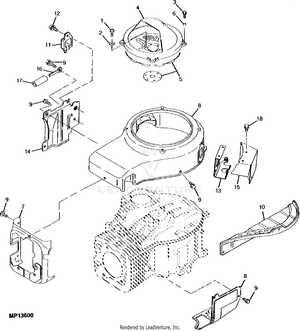
In this system, fluid moves through a series of interconnected lines, each responsible for powering different actuators. The high-pressure lines are built to withstand intense forces, while return lines allow fluid to flow back to the reservoir for reuse. Critical components such as pumps, valves, and cylinders are strategically placed to direct fluid where it is needed.
Component Connectivity
Each part within the hydraulic circuit is linked in a way that ensures maximum efficiency. The pump generates the necessary pressure, which is then directed by control valves toward specific actuators.
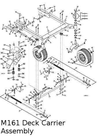
Detailed View of the Steering Assembly
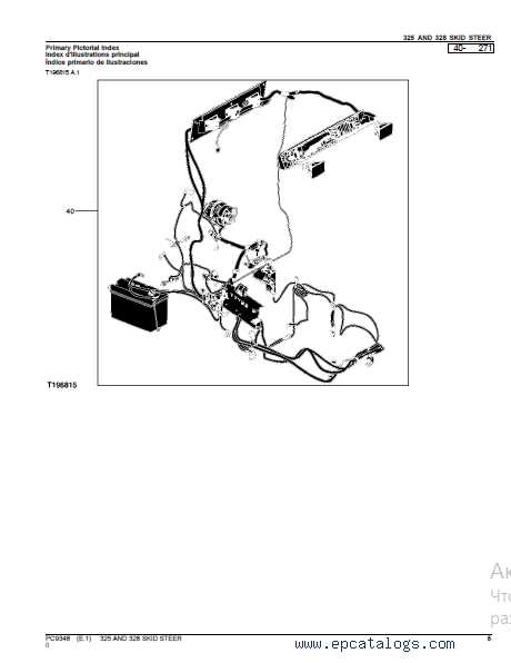
The steering system is a crucial component for ensuring precise control and smooth operation. Understanding how its various elements interact is essential for maintaining the vehicle’s performance and safety. In this section, we will explore the main structures involved, emphasizing their roles in maneuverability and responsiveness. This insight is important for anyone looking to diagnose or repair issues related to directional control.
Key Elements of the Steering Assembly:
The steering mechanism consists of multiple interconnected parts that work in unison to translate the driver’s input into movement. The central linkages and joints ensure that the wheels respond accurately to every adjustment. Additionally, attention must be paid to the column and wheel assembly, as they form the direct interface between the operator and the system.
Proper care and regular inspection of these components will help maintain smooth turning capabilities and prevent premature wear.
Maintenance Tips for Steering Parts
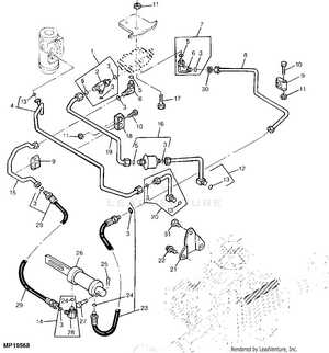
Proper upkeep of steering components is essential for ensuring smooth maneuverability and optimal performance. Regular attention to these elements not only enhances functionality but also extends the lifespan of the equipment. This section outlines key maintenance practices to keep steering mechanisms in excellent condition.
Maintenance Task Frequency Recommended Action Inspect Steering Linkage Monthly Check for wear and tear, and tighten any loose connections. Lubricate Joints Every 100 hours of use Apply appropriate grease to all pivot points to reduce friction. Examine Power Steering Fluid Every 500 hours of use Ensure fluid levels are adequate and replace if contaminated. Check for Leaks Every 50 hours of use Look for any signs of leakage around hoses and seals. Test Steering Response Before each use Ensure that steering is responsive and does not exhibit excessive play. Cutting Deck Configuration Explained

The configuration of a cutting deck plays a crucial role in achieving optimal performance during mowing operations. It encompasses various elements that work in harmony to ensure efficiency and effectiveness in maintaining grass length and health.
Understanding the arrangement of blades, the deck’s shape, and its height adjustments is essential for users looking to achieve specific mowing results. A well-designed cutting surface can enhance the quality of the cut, minimize clumping, and allow for better maneuverability in different terrain conditions.
Blade arrangement significantly impacts the quality of the cut. Multiple blades can provide a cleaner finish by overlapping their paths, ensuring even trimming across the entire width of the deck. Furthermore, the angle and pitch of the blades can influence how grass is lifted and cut, affecting the overall performance.
Additionally, the ability to adjust the cutting height allows users to tailor their mowing experience based on seasonal changes and grass types. Lower settings are ideal for maintaining a neat appearance, while higher settings can promote healthier growth by allowing for more leaf area and sun exposure.
Overall, a thorough understanding of cutting deck configuration empowers users to optimize their mowing practices, leading to a healthier and more visually appealing landscape.
Blade and Belt Arrangement
Understanding the configuration of cutting implements and drive mechanisms is essential for efficient operation and maintenance. This section will explore the layout and interaction between these critical components, ensuring optimal performance in various applications.
Proper alignment and positioning of blades and belts significantly influence the overall functionality. Here are some key aspects to consider:
- Blade Positioning: Ensuring blades are securely mounted and accurately aligned enhances cutting efficiency.
- Belt Tension: Correct tension in the drive belts prevents slippage and promotes smooth operation.
- Adjustment Mechanisms: Familiarity with adjustment options allows for fine-tuning based on specific operational requirements.
- Wear Indicators: Monitoring for signs of wear on both blades and belts aids in timely replacements, reducing downtime.
In addition to these elements, regular inspection of the arrangement can prevent potential issues that may arise from misalignment or excessive wear.
- Inspect blade sharpness and integrity.
- Check belt condition and adjust tension as necessary.
- Ensure all connections are secure and free from debris.
By focusing on these factors, operators can maintain a high level of performance and prolong the lifespan of the cutting system.
Electrical System Connections
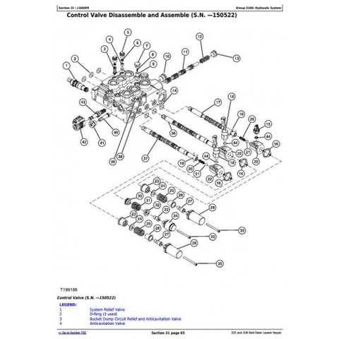
The integrity of an electrical system is crucial for the reliable operation of any machinery. Understanding how various components interconnect is essential for troubleshooting and maintenance. Proper connections ensure that power is efficiently transmitted throughout the system, minimizing the risk of failures.
Wiring harnesses play a vital role in facilitating these connections. They serve as the main conduits for electrical signals, linking various elements such as switches, sensors, and control units. Correctly routed and secured harnesses prevent wear and damage, which can lead to shorts or open circuits.
Additionally, connectors must be inspected regularly to ensure they are free from corrosion and debris. A clean and secure connection is essential for optimal performance. It is also important to verify that the right gauge of wire is used in each segment to handle the required current load effectively.
Lastly, understanding the grounding system is fundamental. Proper grounding protects both the equipment and the operator from electrical faults. Regularly checking these connections helps maintain a safe and functional operational environment.
Battery and Starter Wiring Path
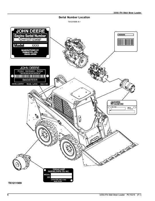
The connection and routing of the power supply and ignition components are crucial for the optimal functioning of the engine system. Understanding the flow of electricity from the energy source to the ignition device ensures reliable starting and performance of the machine. This section outlines the essential pathways involved in this electrical circuit, providing insights into the key connections and components that facilitate smooth operations.
Electrical Connections Overview
In this section, we will delve into the specific connections that link the power source with the ignition apparatus. Properly understanding these links is vital for troubleshooting and maintenance, enabling effective diagnostics and repairs.
Component Wiring Table
Component Connection Type Description Battery Positive and Negative Terminals Supplies electrical energy for starting the engine. Starter Motor Direct Connection Engages the engine during the initial startup phase. Ignition Switch Control Link Controls the flow of electricity from the battery to the starter. Fuses Protective Link Prevents electrical overloads, safeguarding the system. Relay Signal Link Transmits the ignition signal to the starter motor. By following these connections and understanding their roles, one can ensure that the electrical system operates efficiently, allowing for quick engine starts and reliable performance.
Exploring the Cooling Mechanism
The effectiveness of any machinery significantly relies on its ability to manage heat. This section delves into the vital role of the cooling system, designed to maintain optimal operating temperatures and ensure longevity. Understanding this mechanism is crucial for efficient performance and reliability.
Heat Dissipation is one of the primary functions of a cooling system. As engines operate, they generate considerable thermal energy. This heat must be efficiently dissipated to prevent overheating, which can lead to severe damage or reduced efficiency. Various components work in unison to facilitate this process, ensuring that the machinery remains within a safe temperature range.
Fluid Circulation plays a crucial role in the cooling mechanism. A coolant circulates through channels and radiators, absorbing heat from the engine and transferring it to the external environment. This continuous flow is essential for maintaining a balanced thermal state, thus preventing critical failures. Regular maintenance of these fluid pathways is important to ensure unobstructed circulation.
Another vital aspect is the fan operation. This component enhances airflow over the cooling fins or radiator, augmenting heat dissipation. Fans can operate automatically based on temperature readings, ensuring that cooling is adjusted according to the engine’s demands. Efficient fan performance is crucial, especially in high-load scenarios.
In summary, the cooling system is a complex yet essential component that ensures the smooth operation of machinery. Regular checks and maintenance can help sustain its effectiveness, contributing to overall machinery longevity and performance.
Radiator and Fan Assembly Insights
The efficiency of a cooling system is paramount for maintaining optimal operating temperatures in machinery. This assembly plays a crucial role in dissipating heat generated by the engine, ensuring reliable performance during operation. Understanding the components and their functions can aid in effective maintenance and troubleshooting, ultimately extending the lifespan of the equipment.
Key Components
The assembly typically consists of several essential elements, including the radiator, fan, and shroud. The radiator is responsible for transferring heat away from the engine coolant, while the fan enhances airflow through the radiator to facilitate efficient cooling. The shroud helps direct airflow, maximizing the cooling effect by preventing air from escaping around the edges of the radiator.
Maintenance Tips
Regular inspection of the cooling assembly is vital for ensuring optimal performance. Check for any signs of damage, such as leaks or corrosion, which can hinder the system’s efficiency. Additionally, cleaning the radiator and fan blades to remove debris can significantly improve airflow and cooling capacity. Utilizing proper coolant levels and types is also essential for preventing overheating and ensuring long-lasting operation.
Analyzing the Fuel Delivery System
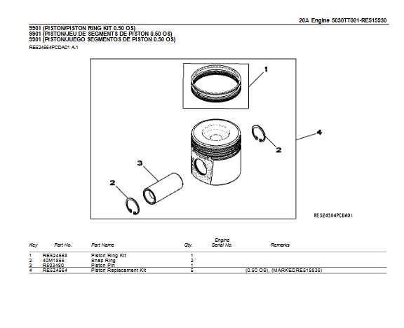
The fuel delivery system is a crucial component that ensures the efficient operation of any engine. Understanding its various elements and their interconnections can lead to improved performance and longevity of the machine. This section focuses on the intricacies of the fuel delivery process, highlighting the essential components that work in harmony to deliver fuel from the tank to the combustion chamber.
Component Function Fuel Tank Stores the fuel necessary for engine operation. Fuel Pump Transports fuel from the tank to the engine at the required pressure. Fuel Filter Removes impurities and contaminants from the fuel before it reaches the engine. Fuel Injector Atomizes the fuel and sprays it into the combustion chamber for optimal mixing with air. Pressure Regulator Maintains the appropriate fuel pressure within the system for effective operation. Each of these components plays a vital role in maintaining a reliable fuel delivery system. Regular maintenance and inspection can prevent potential issues that may arise from wear and tear or contamination. Understanding these elements can aid in troubleshooting and enhancing overall engine performance.