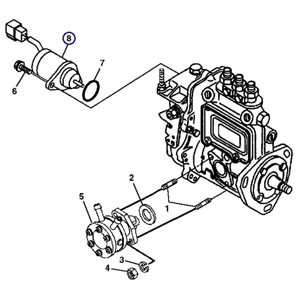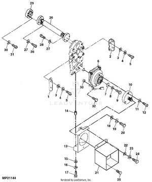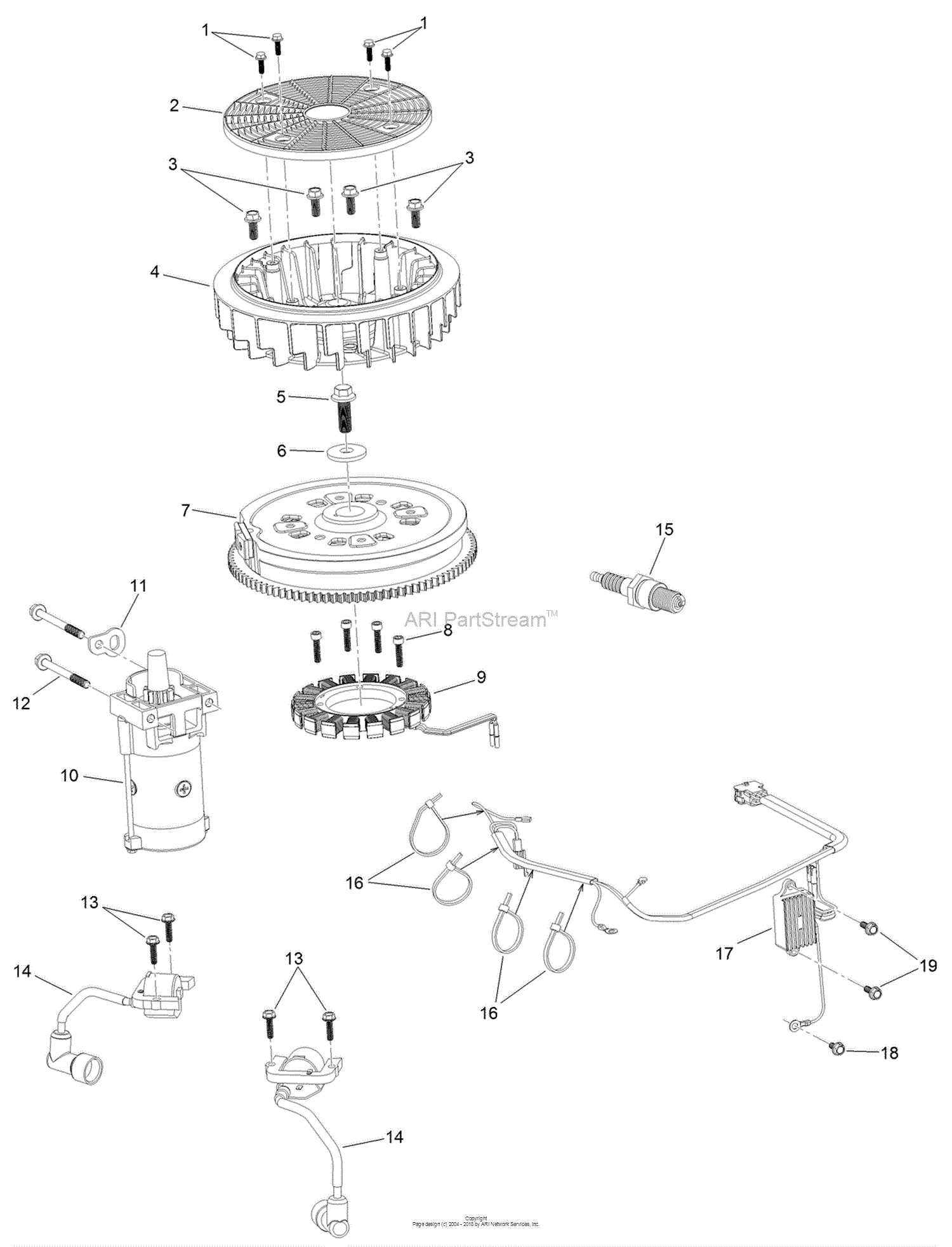
Understanding the intricate arrangement of machinery elements is crucial for maintaining and repairing agricultural equipment. These schematics provide a visual representation of how various components are interconnected, aiding in efficient troubleshooting and ensuring smooth operation. A clear grasp of these layouts is essential for anyone working with farm machinery, as it helps in identifying potential issues before they become significant problems.
By studying these detailed illustrations, users can quickly locate individual elements within the machine, allowing for more straightforward maintenance and repairs. This understanding also ensures that the correct replacement components are chosen, minimizing downtime and maximizing the efficiency of the equipment.
Whether you’re a professional mechanic or an owner seeking to keep your machine in
John Deere 4200 Parts Diagrams
The detailed layout of equipment components allows users to understand the organization of essential mechanisms. This section offers a comprehensive overview of the machine’s inner workings, providing valuable insights into its structure and operational flow. By referencing these visual guides, users can easily identify various elements, which aids in both routine maintenance and repairs.
Key Mechanical Components
A clear representation of major systems, such as the engine, transmission, and hydraulic circuits, ensures a better understanding of their interconnection. Whether inspecting for wear or seeking replacements, the schematics serve as a crucial tool in ensuring the longevity and functionality of the equipment.
Efficiency in Maintenance
Having access to visual breakdowns of different mechanisms simplifies the process of identifying potential issues. With organized charts and labels, users can quickly locate the necessary elements, improving both accuracy and efficiency during upkeep tasks.
Key Components of the Tractor Model
The machinery in question is built using a range of crucial elements that ensure efficient performance and reliability. These components are designed to work together seamlessly, providing users with robust functionality across various tasks. Understanding the primary systems can help in maintaining and troubleshooting the equipment.
At the core of this model lies the engine, known for its durability and power output, which drives the overall mechanism. The transmission system, another critical feature, allows for smooth gear shifts and optimal speed control, ensuring the machine operates at peak efficiency under different conditions.
Additionally, the hydraulic system provides essential support for lifting and other auxiliary functions, making it highly versatile for different agricultural and industrial needs. Each of these systems is engineered for longevity and ease of maintenance, helping to reduce downtime and ensure continuous operation.
Engine Assembly Breakdown
The internal structure of the engine consists of numerous key components that work together to ensure smooth performance. Understanding the arrangement of these elements is crucial for maintaining the engine’s efficiency and resolving any mechanical issues. This section offers an overview of how these components are positioned and how they interact within the engine’s overall structure.
Main Engine Components
At the heart of the engine are the primary elements responsible for combustion and power generation. These include pistons, crankshaft, and connecting rods, each playing a critical role in converting fuel into mechanical energy. The precise alignment of these parts is essential for the engine’s proper function.
Supporting Systems
Beyond the core components, several auxiliary systems contribute to the engine’s overall operation. The cooling and lubrication mechanisms, for instance, help regulate temperature and reduce friction between moving parts, ensuring longevity and reducing wear. These systems are integral to
Transmission Parts Overview
The transmission system is a crucial component that ensures the proper functioning of machinery. It allows for the smooth transfer of power from the engine to the wheels, enabling controlled movement and operation. Understanding the individual elements within the system is essential for maintaining optimal performance and addressing any potential issues.
Main Components of the System

- Gears: These are responsible for regulating the speed and torque, ensuring smooth transitions between different driving conditions.
- Shafts: Essential for transmitting power from one part of the system to another, providing structural integrity to the entire setup.
- Clutch: A mechanism that engages and disengages power flow, allowing for gear changes without stopping the engine.
Maintenance and Care
Regular inspection and upkeep of the transmission system can prevent significant issues. Key areas to focus on include lubrication, alignment
Hydraulic System Components
The hydraulic system is essential for the smooth operation of various mechanical processes, providing the necessary fluid power to operate multiple functions. Understanding the various elements involved in this system is crucial for ensuring effective maintenance and optimal performance. Below is an overview of the main components that contribute to the hydraulic functionality.
| Component | Description | ||||||||||||
|---|---|---|---|---|---|---|---|---|---|---|---|---|---|
| Pump | Responsible for moving hydraulic fluid through the system, creating the pressure needed to power various mechanisms. | ||||||||||||
| Hydraulic Lines | These tubes and hoses transport fluid between components, allowing the system to function without leaks or pressure loss. | ||||||||||||
| Valves | Control the
Steering Mechanism DiagramThe steering system of agricultural machinery plays a crucial role in ensuring precise navigation and maneuverability. This section provides an overview of the components involved in the steering mechanism, highlighting their functions and interactions.
Electrical Wiring LayoutThe electrical wiring configuration is crucial for ensuring optimal functionality and safety in machinery operations. A well-structured layout helps in the effective management of electrical components, allowing for smooth integration and efficient performance. Understanding the arrangement and connections of wiring systems is essential for troubleshooting and maintenance tasks. Components OverviewThis section outlines the primary elements involved in the electrical wiring scheme. These components include various connectors, switches, and relays that play significant roles in controlling electrical flow. Familiarity with these parts enables operators to better understand how electrical signals are transmitted throughout the system. Connection StrategiesEmploying proper connection techniques is vital for maintaining a reliable electrical system. Utilizing high-quality connectors and ensuring secure fittings can prevent potential failures and enhance durability. Regular inspections and adherence to recommended wiring practices contribute to the longevity and safety of the equipment. Fuel System PartsThe fuel system plays a critical role in the overall performance and efficiency of machinery. It is essential for ensuring that the engine receives the right amount of fuel for optimal operation. Understanding the components that make up this system can help in maintenance and troubleshooting. Key components of the fuel system include:
Each component must function properly to maintain system efficiency and prevent engine issues. Regular checks and replacements of these parts contribute to the longevity of the equipment. Brake System ComponentsThe braking system is crucial for ensuring safe and efficient operation of machinery. It consists of various elements that work together to provide reliable stopping power. Understanding these components is essential for maintenance and troubleshooting. Key Elements of the Braking MechanismAt the heart of the braking system is the brake pedal, which activates the hydraulic system when pressed. This action creates pressure in the brake lines, leading to the application of brake pads against the rotors. Other important components include the brake fluid reservoir, which holds the fluid necessary for hydraulic function, and the master cylinder, which converts the pedal movement into hydraulic pressure. Maintenance and InspectionRegular inspection of the braking system is vital for optimal performance. Checking the brake pads for wear, ensuring proper fluid levels, and examining hoses for leaks can prevent failures. Additionally, replacing worn components promptly can enhance the longevity and reliability of the braking system. Cooling System DiagramThe cooling system plays a crucial role in maintaining optimal operating temperatures for machinery. It ensures that the engine runs efficiently by dissipating heat generated during operation. Understanding the layout and components of this system is essential for effective maintenance and troubleshooting. This system typically consists of several key elements, including the radiator, water pump, thermostat, and coolant passages. Each component works together to circulate coolant through the engine, absorbing heat and transferring it to the radiator, where it is cooled before being recirculated. Proper functionality of this system prevents overheating and prolongs the lifespan of the engine. Regular inspection and maintenance of the cooling system components are vital to ensure reliability. Checking for leaks, ensuring proper coolant levels, and verifying the efficiency of the radiator and water pump are essential practices. By following these guidelines, operators can keep their machinery running smoothly and avoid costly repairs. Axle and Drive ComponentsThe axle and drive components play a crucial role in the functionality of any agricultural machine. These elements work together to ensure effective power transfer and stability during operation. Understanding the various parts and their arrangements can help in maintaining optimal performance and extending the lifespan of the equipment. Key Components
Maintenance Tips
|
