For anyone involved in maintaining or repairing agricultural machinery, having a clear understanding of the essential components is vital. The intricate network of mechanical parts that make up these machines requires a well-organized approach to ensure everything functions smoothly. Knowing where each element is located and how they interconnect can greatly enhance the efficiency and longevity of equipment.
In this section, we will delve into the various mechanical assemblies, examining their layout and purpose. Whether you’re troubleshooting a technical issue or conducting routine maintenance, a detailed look at the internal workings will help you navigate the complexities of these machines with confidence.
By exploring this in-depth overview, you’ll be equipped with the knowledge to effectively manage, replace, or repair any vital component. This understanding will support both novice users and experienced technicians in their efforts to keep agricultural equipment operating at peak performance.
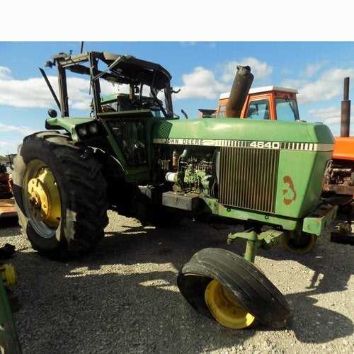
John Deere 4640 Parts Diagram Overview
The breakdown of components for this agricultural machine provides a clear view of how various elements work together. Each section illustrates the function and placement of essential mechanisms, helping users understand the interconnectedness of different systems. This guide assists in identifying the right elements, ensuring smooth operation and easier maintenance.
Key assemblies are shown in detailed layouts, making it easier to navigate through the various mechanical systems. By referring to this visual layout, users can efficiently locate specific components, which simplifies the process of repairs or replacements.
With this structural representation, you can focus on both the exterior and internal elements. The goal is to ensure every system works as intended, with each piece contributing to the overall efficiency of the machine. The visual arrangement is crucial for keeping everything in top working condition.
Main Components of the John Deere 4640
The key elements of this agricultural machinery are essential for ensuring reliable operation and effective performance. Each component plays a vital role in enabling smooth functioning, providing both power and control across various tasks. Below is a breakdown of the main systems that contribute to the overall efficiency of the equipment.
| Component | Description |
|---|---|
| Engine System | Provides the necessary horsepower to drive the machine, offering fuel efficiency and longevity. |
| Transmission | Ensures optimal speed control and power distribution, enabling the equipment to handle various terrains. |
| Hydraulic System | Controls the movement of implements and attachments, allowing for versatile applications in the field. |
| Electrical System | Powers critical functions such as lighting, control panels, and diagnostic systems. |
| Cooling System | Maintains proper engine temperature to prevent overheating, ensuring prolonged operation. |
Hydraulic System Parts and Layout

The hydraulic system is a crucial component in the overall operation, ensuring smooth power transfer and control of various mechanical functions. This system relies on interconnected elements working together to provide consistent pressure and flow to different sections, making the machinery efficient and reliable.
Key Components of the System
- Pumps – Responsible for generating the flow needed to move hydraulic fluid through the system.
- Valves – Control the direction and pressure of the fluid, enabling precise movement of connected parts.
- Cylinders – Convert hydraulic energy into mechanical force, driving the movement of arms or other machinery.
- Filters – Ensure that the fluid remains clean, preventing contamination and damage to sensitive parts.
System Layout Overview
The layout of the hydraulic system is designed to facilitate efficient fluid flow between different components. The pump typically draws fluid from a reservoir, sending it through valves that regulate its movement toward the cylinders. By adjusting valve settings, the operator can control the machinery’s speed and force, making the system adaptable to various tasks.
Engine and Fuel System Details
The engine and fuel system play a crucial role in ensuring optimal performance and efficiency. This section will cover the main components of the engine and how the fuel system contributes to its smooth operation. Understanding these elements is essential for maintaining the overall functionality and longevity of the machinery.
- Engine block: The core structure that houses vital components such as pistons and cylinders, ensuring stability and power output.
- Fuel injection system: A critical component responsible for delivering the right amount of fuel to the engine, improving combustion and efficiency.
- Cooling system: Essential for regulating engine temperature, preventing overheating, and ensuring reliable operation during extended use.
- Air intake: This system provides a clean and sufficient air supply to the engine, enhancing combustion and overall engine performance.
Each of these components works in harmony to deliver reliable power and fuel efficiency. Regular maintenance is key to ensuring that these systems function effectively, reducing the risk of breakdowns and ensuring consistent performance.
Transmission and Clutch Assembly
The transmission and clutch are essential components responsible for ensuring smooth power transfer and control of the machine’s movement. These elements work together to regulate the speed and torque, providing flexibility and efficiency during operation. Understanding the structure and interaction of these systems is crucial for optimal performance and maintenance.
| Component | Function |
|---|---|
| Transmission Gears | Adjust the speed and torque to match the load requirements. |
| Clutch Plate | Engages and disengages the power flow between the engine and transmission. |
| Input Shaft | Transfers power from the engine to the transmission gears. |
| Pressure Plate | Applies force to the clutch disc, allowing the transmission of engine power. |
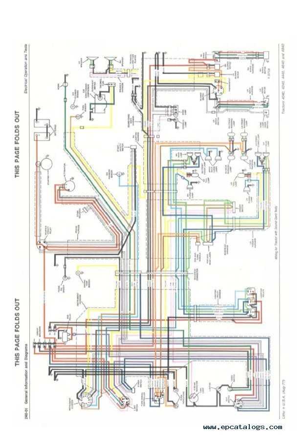
Electrical System and Wiring Overview
The electrical system in agricultural machinery plays a crucial role in ensuring that all components work seamlessly. This section offers a detailed look into the wiring framework and how it contributes to the machine’s overall functionality. Understanding the layout of the system helps operators and technicians maintain and troubleshoot the equipment efficiently.
Key Wiring Components
The wiring network connects essential parts, including the ignition system, lighting, and various sensors, allowing the machine to operate safely and efficiently. Proper wiring ensures that electrical signals are transmitted without interruption, reducing the risk of malfunctions.
Maintenance Tips for Electrical Systems
Regular inspections of the wiring and electrical connections are essential for preventing system failures. Checking for wear, corrosion, and loose connections can help maintain a reliable electrical system and avoid unexpected breakdowns in the field.
Cooling System Components and Diagram
The cooling system plays a critical role in maintaining the optimal temperature of the engine. By ensuring proper heat dissipation, the system prevents overheating, which can lead to serious damage. A well-functioning cooling mechanism is essential for consistent performance, especially under heavy workloads.
Key elements of the cooling system include various interconnected components that help regulate the engine’s temperature. The radiator, coolant pump, and thermostat work together to keep the temperature within an ideal range. Fluid is circulated through the system, absorbing excess heat and releasing it as needed. The correct balance of pressure and flow within these parts ensures reliable operation.
The diagram of this system highlights the flow of coolant and the positioning of major components. Understanding how these parts interact can help in troubleshooting and ensuring efficient cooling under all conditions.
Rear Axle and Differential Breakdown
The rear axle and differential are critical components responsible for transferring power from the engine to the wheels. This system ensures that torque is distributed effectively, allowing the vehicle to handle various terrain conditions with stability and control.
Axle Structure and Function
The axle assembly is designed to withstand heavy loads, providing support to the weight of the vehicle while allowing the wheels to rotate freely. It is engineered to handle stress and distribute force evenly across both rear wheels, ensuring smooth movement during operation.
Differential Mechanism
The differential mechanism plays a vital role in adjusting wheel speed when turning. It allows the wheels on each side to rotate at different speeds, preventing skidding and ensuring better maneuverability. This component is essential for maintaining traction and balance, especially during sharp turns or uneven ground.
Cab and Interior Part Locations
The interior and control elements of the cabin are designed to provide comfort and ease of use. Each component is carefully positioned for optimal functionality and operator convenience. Understanding the layout is essential for maintaining efficiency and ensuring a seamless work environment.
Seat adjustments are located centrally, allowing the operator to modify their seating position with ease. This ensures proper posture and comfort during long working hours.
The steering column features a variety of controls that are positioned within easy reach, providing quick access to essential functions without compromising safety.
Additional controls for climate settings, lighting, and other internal systems are strategically placed around the operator, making it simple to adjust settings without taking attention away from the task at hand.
Brake System and Key Components
The brake mechanism is critical for ensuring the safe and reliable operation of heavy machinery. It includes various interconnected elements that work together to manage stopping power and control under different conditions. Understanding the functionality and structure of these parts is essential for maintaining optimal performance and safety.
Main Components of the Brake System
- Brake Pedal: The component that initiates the braking process when pressed, transferring force to the other elements of the system.
- Hydraulic Lines: Channels through which the fluid pressure is transferred, enabling the activation of the brakes.
- Master Cylinder: Converts the force applied to the pedal into hydraulic pressure, distributing it to the brake calipers.
- Brake Calipers: Devices that apply pressure to the brake pads, which then create friction against the rotors.
Ensuring System Integrity
- Fluid Levels: Regular checks on hydraulic fluid levels are essential to maintain proper system pressure.
- Wear Monitoring: Keep an eye on the condition of brake pads and rotors, as worn-out parts can compromise safety.
- Line Inspections: Inspect hydraulic lines for any leaks or damage to prevent pressure loss during braking.
Steering System Parts Layout
The steering mechanism of agricultural machinery is a crucial component that ensures precise and responsive control during operation. This section provides a detailed overview of how the essential elements are arranged within the steering assembly, contributing to the machine’s ability to navigate various terrains smoothly and efficiently.
Key Components and Their Arrangement
At the core of the system, several interconnected elements work together to translate the driver’s inputs into accurate directional changes. These include the hydraulic control unit, linkage arms, and the main steering column. Each component plays a specific role in transferring power and maintaining the fluid movement necessary for smooth steering functionality.
Hydraulic Integration and Control
Hydraulic fluid is routed through valves and hoses, ensuring the pressure needed to adjust the wheels is maintained at optimal levels. This setup allows for quick adjustments with minimal effort, ensuring that the vehicle responds precisely to the operator’s commands, especially in challenging working environments.
Front Axle and Suspension Components

The front axle and suspension elements play a crucial role in ensuring optimal performance and stability in heavy machinery. These components are designed to support the vehicle’s weight while providing essential mobility and handling characteristics. Understanding their structure and function is vital for effective maintenance and repair.
Overview of Key Elements
Central to the front axle assembly are various parts that contribute to the overall strength and durability of the system. These include the axle housing, wheel hubs, and suspension arms. Each component is engineered to withstand significant loads and provide a smooth driving experience.
Maintenance Considerations
Regular inspection and maintenance of the front axle and suspension components are essential for preventing premature wear. Lubrication of joints and checking for wear and tear can help ensure the longevity of these critical parts. Neglecting this aspect may lead to reduced performance and potential safety hazards.
Maintenance and Service Part Locations
This section provides an overview of the essential locations for maintenance and service components on your agricultural machinery. Understanding these areas is crucial for ensuring optimal performance and longevity of the equipment.
Identifying Key Components
Familiarizing yourself with the locations of vital elements such as filters, belts, and fluid reservoirs can greatly enhance your maintenance efficiency. Regular checks in these areas can prevent unforeseen issues and promote smooth operation.
Accessibility and Inspection
Accessible placement of service items allows for quick inspections and timely replacements. Keeping a close eye on these components can help in maintaining peak functionality. Ensure that you consult the manufacturer’s guidelines for specific locations and recommended service intervals.
Remember: A proactive approach to maintenance is key to extending the life of your machinery and reducing potential downtime.