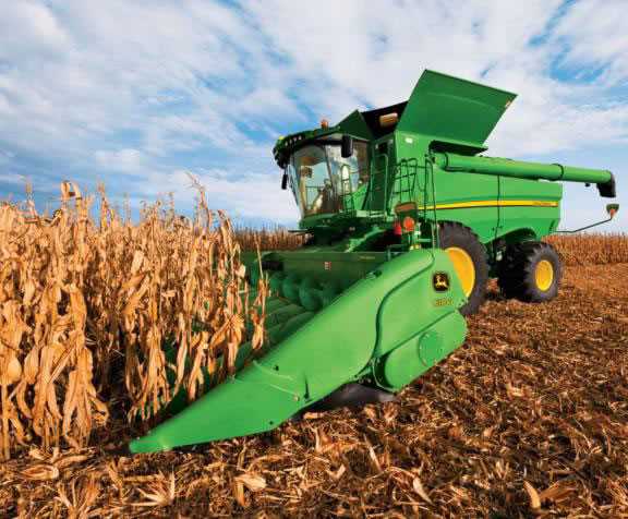
Understanding the various elements that make up complex machinery is essential for ensuring smooth and efficient operation. Each segment of the equipment plays a critical role in maintaining optimal performance, and having detailed knowledge of these components can help prevent malfunctions and downtime. The following section delves into the structure and configuration of key parts, offering insights into their functions and maintenance.
Efficient machinery operation depends on the proper alignment and integration of numerous elements. Knowing how each piece fits and works together is crucial for ensuring longevity and functionality. In this overview, we will explore specific sections of agricultural machinery, focusing on their purpose and maintenance practices to enhance durability and performance.
Understanding the Structure of a Flex Header
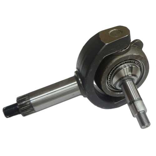
The core mechanism of these agricultural attachments is designed to efficiently collect and process crops during harvest. Its adaptable features allow it to adjust to varying field conditions, ensuring optimal performance in uneven terrains. The structure consists of multiple interconnected components that work together to provide a smooth cutting action and consistent crop flow.
Main Functional Sections

The primary section includes a cutting system that adjusts according to ground level, minimizing crop loss. Additionally, the material conveyance system ensures that harvested crops are transported from the front mechanism to the processing unit without any interruptions.
Key Mechanical Elements
Several vital elements are responsible for the tool’s precision and durability. These include the cutting blades, which can self-adjust to terrain changes, and the drive system, which powers the operation. Proper alignment and regular maintenance of these elements are crucial for peak efficiency.
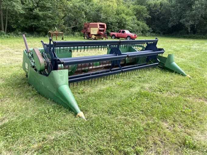
Main Components of the 920 Flex Header
The structure of this agricultural implement is designed for optimal performance during harvesting. It includes several essential elements that work together to ensure efficient crop collection. Understanding the key components can help improve maintenance and ensure the smooth operation of the equipment.
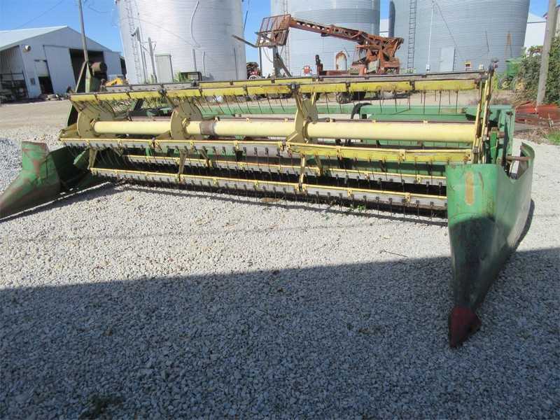
One of the primary sections is the cutting mechanism, which is responsible for slicing through crops at ground level. This part is supported by a complex system that adjusts to varying field conditions. Another important aspect is the reel system, which guides the crops towards the cutting area, ensuring consistent feeding.
Additionally, the platform features height adjustment options, allowing it to adapt to uneven terrain and optimize harvesting efficiency. The drive system powers the entire unit, ensuring synchronization between all moving parts. Proper maintenance of these core components is crucial for the equipment’s longevity and performance.
Hydraulic Mechanisms and Their Function
Hydraulic systems play a crucial role in ensuring efficient operations in various equipment, allowing for the transfer of energy through fluid pressure. These mechanisms offer precise control and power, making them essential for handling complex movements and adjustments in heavy machinery.
Main Components of Hydraulic Systems
At the core of any hydraulic system are essential components that work together to manage pressure and flow. These include pumps, valves, cylinders, and motors, each responsible for converting and controlling energy to achieve the desired motion.
Flow Regulation and Power Transmission
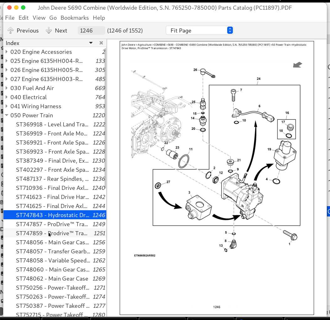
Flow regulation ensures smooth operation, adjusting the speed and direction of hydraulic energy. Through valves and actuators, the power is transmitted to various parts of the machinery, ensuring the correct application of force and movement.
| Component | Function | |||||||
|---|---|---|---|---|---|---|---|---|
| Pump | Generates fluid flow and pressure | |||||||
| Valve | Controls fluid direction and flow rate | |||||||
| Cylinder |
| Component | Inspection Tips |
|---|---|
| Auger Blades | Check for chips or cracks. |
| Bearings | Listen for unusual noises during operation. |
| Drive Belts | Examine for fraying or signs of wear. |
Lubrication and Cleaning
Keeping all moving parts well-lubricated reduces friction and prevents premature wear. Additionally, regular cleaning helps maintain performance and prevents material buildup that can lead to blockages.
Safety Features of the 920 Flex Header
The design of this agricultural implement prioritizes operator protection and equipment longevity. Innovative mechanisms are integrated to minimize risks and enhance user confidence during operation.
One notable aspect is the automatic shut-off system, which activates in case of unexpected movements or obstructions. This feature ensures immediate response, reducing the likelihood of accidents and potential damage.
Additionally, the inclusion of reinforced guards serves to protect vital components from debris and impact, contributing to both safety and durability. Operators can work with peace of mind, knowing that the machinery is equipped with advanced protective measures.
Moreover, the ergonomic layout of control systems allows for intuitive operation, reducing the chances of human error. Clear visibility and accessibility enhance the overall safety experience for users during various tasks.
Electrical System and Control Panel Overview
This section delves into the essential components of the electrical framework and the control interface used in modern agricultural machinery. Understanding these elements is crucial for optimal functionality and efficient operation.
Key Components of the Electrical System
- Power Supply Unit: Provides the necessary energy for operation.
- Wiring Harness: Connects various electrical components, ensuring smooth communication.
- Sensors: Monitor critical parameters, enhancing operational efficiency.
- Control Modules: Process input signals and execute commands for machinery functions.
Control Panel Features
- Display Screen: Provides real-time data and diagnostics.
- Control Buttons: Allow users to adjust settings and control functions.
- Indicator Lights: Signal the status of various systems, ensuring user awareness.
- Emergency Shut-off: Ensures safety by quickly disabling operations in critical situations.
Understanding the interaction between these components is vital for effective troubleshooting and maintenance, ultimately leading to improved performance and longevity of the equipment.
Lubrication Points and Maintenance Schedule
Regular upkeep of agricultural equipment is essential for optimal performance and longevity. This section outlines key areas for lubrication and provides a suggested timetable for maintenance activities to ensure the machine operates efficiently.
Lubrication should be performed at the following critical points:
- Pivot points of moving parts
- Bearings and roller assemblies
- Drive shafts and joints
- Gearboxes and lubrication reservoirs
The maintenance schedule should adhere to the following recommendations:
- Daily: Inspect and lubricate high-wear components, checking for any signs of wear or damage.
- Weekly: Clean all grease fittings and ensure they are free from debris.
- Monthly: Conduct a thorough check of all lubrication points, applying grease as needed.
- Seasonally: Perform a comprehensive maintenance review, replacing worn parts and ensuring all lubrication systems are functioning correctly.
By following these guidelines, operators can maintain peak efficiency and extend the lifespan of their equipment.
