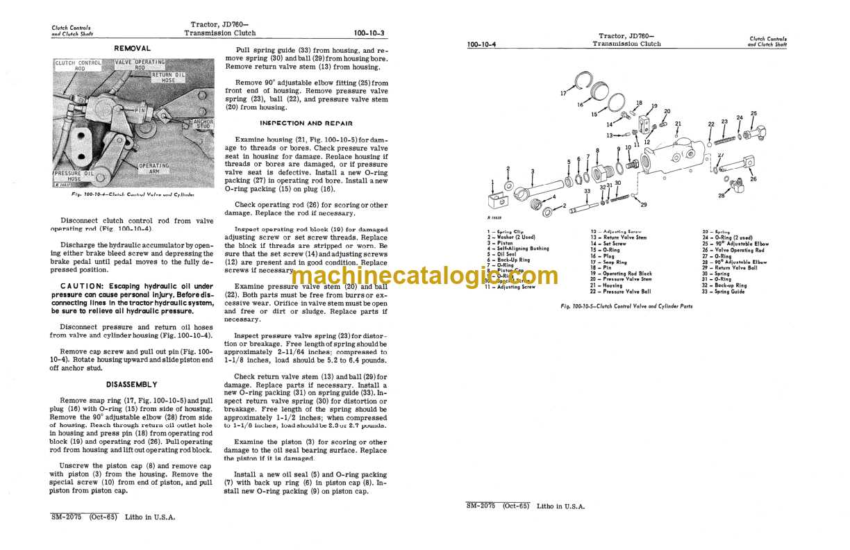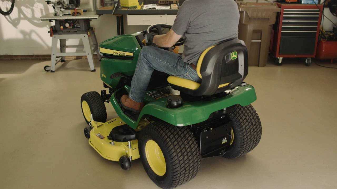
Discovering detailed illustrations of components, exploring intricate layouts, and gaining insights into the inner workings of machinery are all made possible through accessible graphical representations.
Unveiling these visual aids not only facilitates understanding but also enhances troubleshooting capabilities, enabling efficient maintenance and repair processes.
Embarking on a journey through these informative diagrams offers a comprehensive view, guiding enthusiasts and professionals alike through the complexities of mechanical structures.
Exploring John Deere Parts Diagrams: A Comprehensive Guide
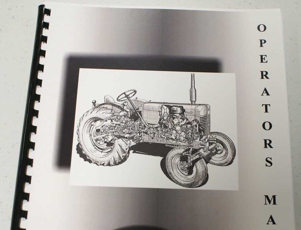
In this section, we delve into the detailed visual representations that aid in understanding the structure and assembly of equipment components. These visual aids are pivotal in enhancing comprehension of how various elements fit together within the machinery framework.
Understanding Visual Schematics
Visual schematics serve as informative blueprints, offering a clear depiction of component interrelations. They facilitate identification of individual parts and their respective placements, crucial for both maintenance and repair tasks.
Interpreting Parts Listings
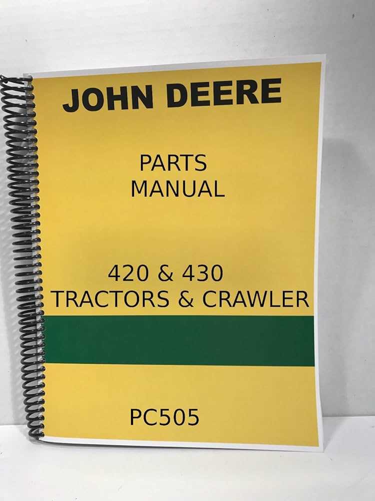
Parts listings provide comprehensive inventories, listing various elements and their specifications. These detailed listings aid in pinpointing exact components needed for maintenance, ensuring accuracy in replacement and repair procedures.
| Component | Description | Part Number |
|---|---|---|
| Engine Assembly | Complete engine unit including cylinders and fuel system | JDPN12345 |
| Hydraulic Pump | Component responsible for hydraulic system pressure | JDPN67890 |
| Transmission | System for transferring power from engine to wheels | JDPN24680 |
Understanding the Importance of Diagrams for Agricultural Equipment
When maintaining and repairing agricultural machinery, having clear visual guides is essential for efficient troubleshooting and part identification. These visual aids serve as crucial references that aid in quickly identifying components, understanding their relationships, and facilitating accurate repairs.
| Enhanced Efficiency | By providing a clear roadmap of the equipment’s structure and parts, these diagrams streamline the maintenance process, reducing downtime and optimizing operational efficiency. |
| Accurate Identification | Diagrams enable precise identification of components, ensuring that the correct parts are ordered and installed, minimizing errors and unnecessary replacements. |
| Comprehensive Understanding | They offer a comprehensive view of the machinery’s assembly, empowering technicians and operators with in-depth knowledge of how each part contributes to overall functionality. |
| Visual Clarity | Visual clarity provided by these diagrams aids in training new personnel and refreshing the knowledge of experienced technicians, fostering a skilled workforce. |
| Improving Safety | Clear diagrams contribute to safer working environments by promoting proper handling procedures and reducing the risk of accidents during maintenance and repair tasks. |
In conclusion, diagrams play a pivotal role in maintaining agricultural equipment by enhancing efficiency, ensuring accuracy, deepening understanding, promoting safety, and ultimately contributing to the overall reliability and longevity of machinery.
How to Access John Deere Parts Schematics Without Cost

To explore comprehensive guides for maintaining and repairing John Deere machinery, discovering accessible and detailed visual representations of component assemblies is invaluable. Finding these essential resources online involves navigating through authorized platforms offering detailed breakdowns of equipment systems.
Locate the official channels where these resources are hosted, ensuring reliability and accuracy in your search for detailed part configurations. This process involves understanding the layout of the machinery and its component functionalities.
Identify platforms that provide these resources for your convenience. Access these diagrams to facilitate efficient maintenance and troubleshooting procedures.
Key Components Found in Parts Schematics for John Deere Equipment
In exploring the intricate details of schematics for agricultural machinery, one encounters essential elements that form the backbone of these technical illustrations. These depictions not only highlight the core parts and their interconnections but also provide a visual roadmap for maintenance and assembly. Understanding these components is crucial for technicians and operators alike, enabling efficient troubleshooting and precise part identification.
- Core Elements: Fundamental components that serve as the foundation for the entire system.
- Connective Interfaces: Interlocking mechanisms that facilitate seamless integration between various parts.
- Operational Nodes: Key points where different parts converge to perform specific functions.
- Support Structures: Frameworks and brackets that uphold the integrity of the assembly.
- Peripheral Devices: Additional components that enhance the operational capabilities of the equipment.
Each diagrammatic representation not only delineates the physical arrangement of parts but also elucidates their functional relationships, aiding in the precise identification of components during repairs and maintenance routines.
Interpreting John Deere Parts Diagram Symbols
Understanding the symbols used in mechanical illustrations is crucial for effective maintenance and repair. These graphical representations convey vital information about components and their interrelations, enhancing the ability to identify parts and streamline the repair process.
Key Symbols and Their Meanings
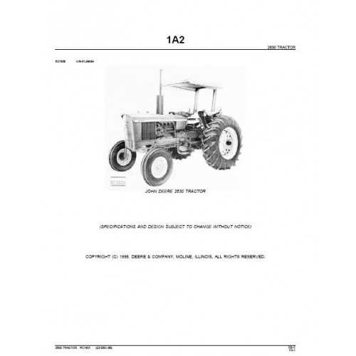
Each symbol holds specific significance, helping users decipher the intricate connections between various elements. Familiarity with these icons facilitates quicker troubleshooting and ensures that replacements are executed accurately.
Commonly Encountered Icons
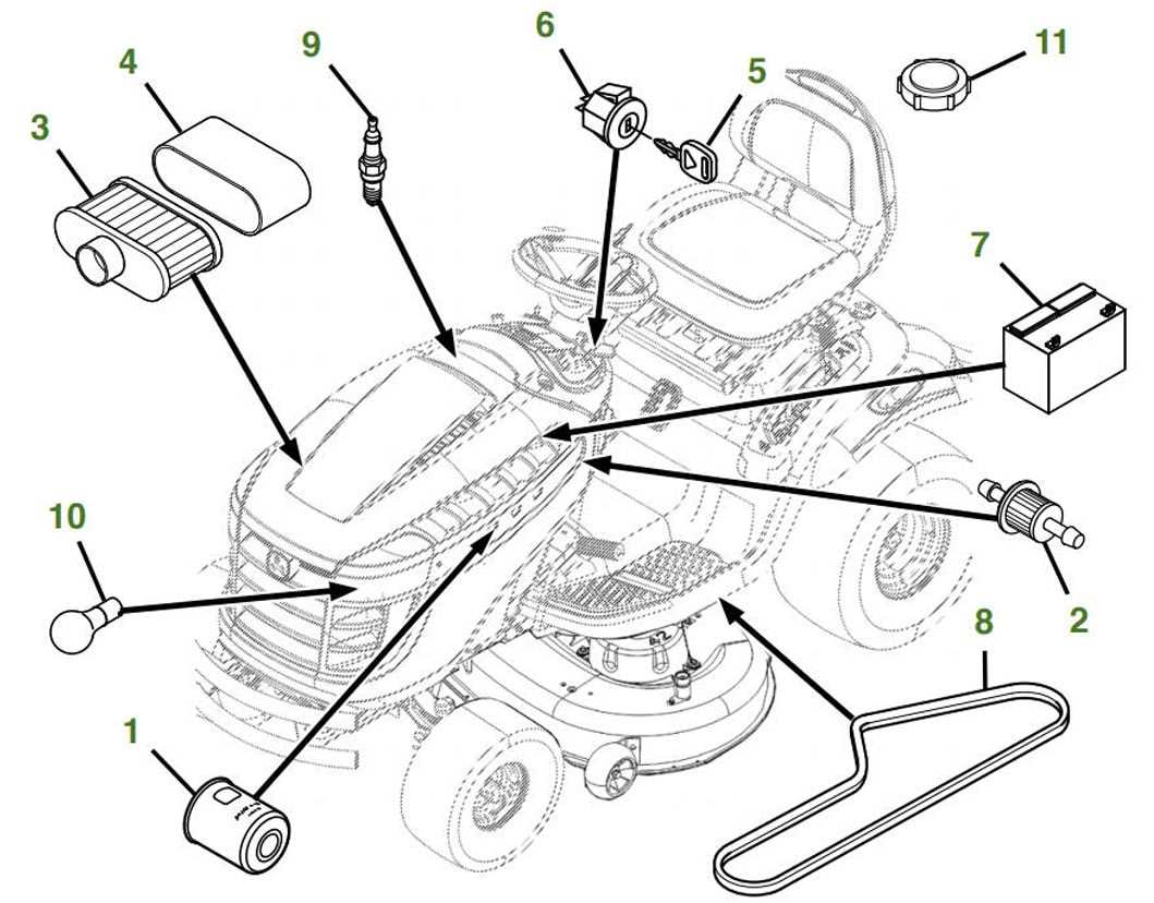
| Symbol | Meaning |
|---|---|
| ⚙️ | Gear or rotating component |
| Fastener or screw | |
| Tool required for assembly | |
| ️ | General maintenance task |
Common Uses of John Deere Parts Diagrams
Understanding the various components of machinery is crucial for maintenance and repair tasks. Visual representations serve as invaluable tools for users seeking to navigate the intricacies of equipment assembly and disassembly. These resources enhance comprehension and facilitate effective troubleshooting.
One primary application involves aiding technicians in identifying individual elements within complex systems. By referencing illustrations, professionals can quickly locate and assess specific items, streamlining their repair processes. This efficiency significantly reduces downtime and enhances productivity in various agricultural and industrial settings.
Additionally, these visuals assist in ordering the correct components when replacements are necessary. Clear depictions ensure that users can accurately convey their needs to suppliers, minimizing the risk of acquiring incompatible parts. This clarity supports timely repairs and keeps machinery operational.
Furthermore, educational purposes cannot be overlooked. Training programs for new operators often incorporate these visuals to provide foundational knowledge. Understanding machinery layouts and component functions through graphical aids helps foster a more competent workforce, ultimately contributing to safer and more efficient operations.
Benefits of Using Free John Deere Parts Diagrams
Accessing complimentary visual representations of equipment components offers numerous advantages for users looking to enhance their maintenance and repair efforts. These resources can significantly improve understanding and facilitate efficient problem-solving.
- Cost-effectiveness: Utilizing no-cost resources eliminates the need for expensive manuals or guides, allowing for better budgeting and resource allocation.
- Enhanced understanding: Visual aids provide clearer insights into component arrangement, making it easier to identify issues and plan repairs.
- Time-saving: Quick access to visuals accelerates the troubleshooting process, minimizing downtime and increasing productivity.
- User-friendly: These resources are often designed for easy navigation, enabling even those with limited technical skills to comprehend and apply the information effectively.
- Community support: Many platforms encourage sharing and discussing these resources, fostering a collaborative environment for knowledge exchange among users.
Comparing John Deere Parts Diagrams with Other Brands
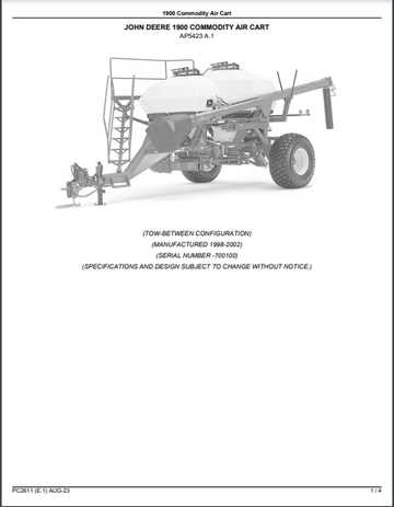
When evaluating technical schematics for various machinery manufacturers, it’s crucial to consider the clarity and ease of use provided by each brand. Some companies offer more intuitive designs, while others may present their components in a more complex manner. Understanding these differences can help users find the most efficient way to repair or maintain their equipment.
Clarity and Usability
The visual presentation and organization of mechanical breakdowns vary significantly between brands. Some offer highly detailed, user-friendly formats that make identifying specific components straightforward, while others might require more effort to navigate.
Accessibility of Information
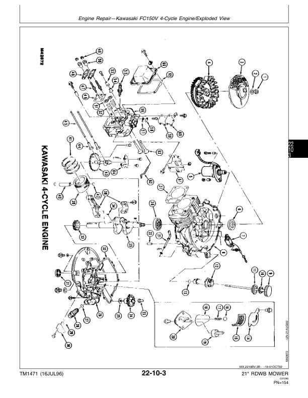
In terms of accessibility, certain manufacturers prioritize open access to their technical resources, allowing users to explore various maintenance options with ease. On the other hand, some companies restrict access to these materials, requiring users to seek specialized services or subscriptions.
Tips for Efficiently Using Equipment Schematics
Understanding how to navigate through technical illustrations can significantly enhance your ability to maintain and repair machinery. These drawings provide crucial insights into how different components are interconnected, helping you find and replace items with ease.
Organize Information Clearly
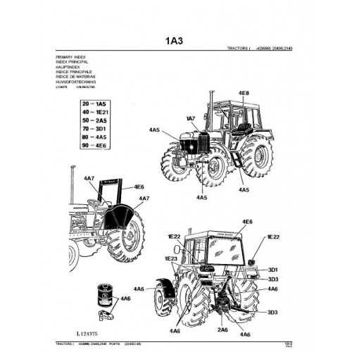
When consulting these schematics, it’s important to organize the information in a way that makes sense to you. Whether it’s highlighting key elements or using notes, finding a clear method to process the details will save you time and effort.
Focus on Key Components
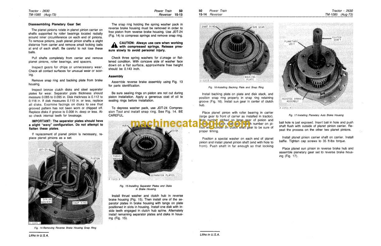
Not every part of the drawing may be relevant to your specific task. Focus on the key elements related to your maintenance or repair job. Understanding the core elements will ensure you’re addressing the correct areas and streamline the entire process.
| Strategy | Benefit |
|---|---|
| Use color-coded notes | Helps distinguish components quickly |
| Key Elements | Interpreting these diagrams requires a grasp of fundamental symbols and their meanings, akin to reading a specialized map or blueprint. |
| Component Identification | Locating individual parts within the schematic helps pinpoint their roles and interactions within the broader machinery context. |
| Navigation Tips | Following a systematic approach to tracing connections and pathways ensures a methodical examination of the schematic, facilitating efficient troubleshooting. |
| Practical Application | Applying theoretical knowledge from the schematic to practical tasks like maintenance or repair enhances precision and reduces downtime. |
Practical Applications of Equipment Component Schematics in Maintenance
Using visual guides for machinery components is essential for effective upkeep. These illustrations provide clear and detailed views of how each element of the machine fits together, ensuring that maintenance processes are precise and efficient. By following these diagrams, technicians can identify issues, replace malfunctioning parts, and perform repairs with confidence.
- Helps in identifying the right replacement parts quickly
- Ensures correct assembly of components after repairs
- Reduces the risk of misplacing or damaging key elements
- Provides a structured guide for routine maintenance tasks
Whether for troubleshooting or regular servicing, such schematics are invaluable tools for anyone working with complex machinery. They not only streamline the repair process but also enhance overall equipment longevity.
