dewalt dcp580 parts diagram

Understanding how various tools are constructed and how their individual elements work together is key to maintaining and repairing them. By gaining insight into the detailed structure, users can easily identify specific features and ensure everything functions as intended. A clear understanding of each part’s role can greatly enhance the longevity of any equipment.

In this guide, we’ll delve into the internal structure of a popular power tool, focusing on its most crucial components. We’ll explore each element’s function and how they contribute to the overall performance. This will provide users with a better grasp of how to maintain their equipment and troubleshoot any issues that may arise.

Through detailed illustrations and descriptions, we will break down the device into its core segments, making it easier to identify, replace, or repair various elements. Whether you’re a professional or an enthusiast, having access to this information will help you handle technical tasks with confidence.

Dewalt DCP580: Detailed Component Overview

This section provides an in-depth look at the key components that make up the handheld planer, offering insights into the functions and roles of each part within the tool’s system. The following breakdown will help users understand how the various elements work together to ensure efficient performance.

Main Assembly Elements

dewalt dcp580 parts diagram

The core structure of the planer includes several interconnected elements, all designed to enhance precision and user control. These parts form the base of the tool, ensuring stability and smooth operation.

Key Features of the Dewalt DCP580 Planer

This high-performance planer is designed to provide smooth and precise cuts, ensuring an efficient workflow for any woodworking project. Its ergonomic build and advanced capabilities make it an essential tool for both professionals and hobbyists alike. Below are some of the standout attributes that make this model particularly effective for achieving top-quality results.

Powerful Motor for Consistent Results

The robust motor ensures consistent performance even during demanding tasks. With ample power, this planer maintains a steady cutting pace, allowing users to tackle various types of wood with ease. This power level ensures that even challenging materials are handled without sacrificing precision or speed.

Enhanced Depth Adjustment Mechanism

A precise depth control system allows users to make fine adjustments, ensuring that every cut is accurate and consistent

How the Planer Motor Works

The motor is the core component of a planer, responsible for driving the blades and ensuring smooth and consistent material removal. It transforms electrical energy into mechanical motion, allowing the machine to handle various woodworking tasks with precision. Understanding how this mechanism operates can help in maintaining the tool’s efficiency.

Key Components of the Motor

  • Rotor and Stator: The interaction between these two elements generates the necessary rotational force to turn the blades.
  • Carbon Brushes: These conductive parts ensure electrical contact with the rotating section, enabling a continuous current flow.
  • Bearings: Positioned around the motor shaft, these provide smooth motion and reduce friction during operation.

Operating Principles

dewalt dcp580 parts diagram

  1. When powered on, the motor receives

    Exploring the Blade System of the DCP580

    The blade mechanism in a planer plays a crucial role in ensuring smooth, precise cuts. Understanding the core components and how they interact allows users to maintain high performance and durability over time. In this section, we will delve into the key elements of the blade setup, focusing on their functionality and interaction within the tool.

    Main Components of the Blade System

    • Cutter Blades: These are the sharp elements responsible for shaving material off the surface, ensuring clean cuts.
    • Blade Holder: The component that securely fastens the cutting blades in place, preventing movement during operation.
    • Adjustment Screws: Used to precisely align the blades, enabling consistent and even cutting performance.

    How the Blade Mechanism Works

    The blade

    Understanding the Depth Adjustment Mechanism

    One of the key components in maintaining precise functionality is the mechanism responsible for depth control. This feature allows users to achieve consistent results by fine-tuning how much material is removed during each pass.

    How the Adjustment Works

    The depth control system consists of a knob or lever that engages with internal components. When adjusted, it shifts the cutting element to increase or decrease the depth at which it engages with the surface. This precise movement ensures smooth operation and adaptability for different tasks.

    Steps to Adjust Properly

    1. Ensure the device is turned off and secure before making any adjustments.
    2. Turn the control knob to the desired position, considering the material and intended depth.
    3. Lock the mechanism in place after making the necessary changes to prevent unintended shifts during use.

    Component Layout and Functionality

    The arrangement and purpose of various elements in this tool are designed for optimal performance and ease of use. Each component is carefully positioned to ensure smooth operation, allowing for efficient handling and precise results.

    Handle and Grip: The ergonomic design provides comfort during prolonged use, minimizing strain. The grip enhances control and stability, enabling precise movements even in challenging conditions.

    Motor Housing: The central unit contains the power source, ensuring that all mechanical parts are well-protected and properly aligned. This contributes to the overall durability and reliable performance of the tool.

    Adjustment Controls: Located strategically for easy access, these controls allow users to make fine adjustments swiftly, adapting the tool’s function to various materials and tasks. Their intuitive layout ensures seamless modifications during operation.

    Drive Belt and Pulley Configuration

    The drive belt and pulley arrangement is crucial for the efficient operation of power tools, influencing performance and longevity. Understanding how these components interact can help users maintain optimal functionality and troubleshoot potential issues effectively.

    Key Components

    • Drive Belt: This flexible loop transmits power from the motor to the pulley system, facilitating motion.
    • Pulleys: These rotating discs guide the drive belt and alter its direction and speed, allowing for versatile operation.
    • Tension Mechanism: Ensures the drive belt maintains appropriate tension, preventing slippage and wear.

    Configuration Overview

    dewalt dcp580 parts diagram

    The configuration of the drive belt and pulleys involves several considerations to ensure efficient power transfer:

    1. Proper alignment is essential; misalignment can cause increased wear and reduced performance.
    2. Ensure the belt is of the correct length and width, as improper sizing can lead to slippage.
    3. Regular inspection for signs of wear, such as fraying or cracking, is vital to prevent sudden failures.

    Handle Design and Ergonomic Benefits

    The handle design of power tools plays a crucial role in enhancing user experience and performance. A thoughtfully crafted grip can significantly reduce fatigue during extended usage, allowing for more efficient and comfortable operation. Ergonomics in tool design prioritizes the natural position of the hand, which can lead to better control and precision when handling the equipment.

    Comfort and Control

    Incorporating contours and soft-touch materials into the handle design provides users with a secure grip, minimizing slippage even in demanding conditions. This comfort translates into improved control over the tool, enabling users to execute tasks with greater accuracy. Additionally, handles designed with user fatigue in mind can allow for longer work sessions without compromising safety or performance.

    Reducing Strain and Enhancing Safety

    By promoting a neutral wrist position, ergonomic handles help alleviate strain on the user’s hands and arms. This design consideration is essential for preventing injuries associated with prolonged tool usage. Furthermore, an optimally designed grip can enhance overall safety by ensuring that the tool remains firmly in the user’s hand, reducing the risk of accidents during operation.

    Maintenance Tips for the Planer Parts

    dewalt dcp580 parts diagram

    Proper upkeep of your planer components is essential for ensuring optimal performance and longevity. Regular maintenance not only enhances efficiency but also prevents potential issues that could disrupt your work.

    Here are some key maintenance practices to keep your equipment running smoothly:

    • Regular Cleaning: After each use, remove any shavings and dust from the machine. Use a soft brush or compressed air to clean hard-to-reach areas.
    • Inspect Blades: Periodically check the cutting edges for dullness or damage. Sharp blades ensure a clean cut and reduce strain on the motor.
    • Lubrication: Apply lubricant to the moving parts as specified in the user manual. Proper lubrication reduces friction and wear.
    • Check Fasteners: Ensure that all screws and bolts are tightened properly. Loose fasteners can lead to misalignment and affect performance.
    • Store Properly: When not in use, store the tool in a dry place. Protect it from moisture to prevent rust and corrosion.

    By following these maintenance tips, you can enhance the efficiency and lifespan of your tool, ensuring it remains a reliable asset in your workshop.

    Power Cord and Electrical System

    The electrical framework of a power tool plays a crucial role in its overall performance and safety. This system includes components responsible for supplying electricity, ensuring that the device operates efficiently while minimizing risks associated with electrical failures. Understanding the intricacies of the power cord and electrical setup is essential for maintenance and optimal functionality.

    Power Cord Specifications

    The power cord is a vital element that connects the tool to an electrical outlet. It must meet specific standards to ensure safety and reliability. Here are some key features to consider:

Component Function
Cutterhead Responsible for material removal, the cutterhead spins at high speed to plane surfaces with accuracy.
Motor
Specification Description
Length Typically ranges from 6 to 10 feet, allowing flexibility during use.
Gauge Commonly 16 or 14 AWG, indicating the thickness of the wire, affecting current capacity.
Material Usually made of rubber or PVC for durability and resistance to abrasion.
Connector Type Standard three-prong design to ensure proper grounding and safety.

Electrical Components

In addition to the power cord, the electrical system comprises various components that ensure proper operation. Key parts include:

Component Function
Motor Converts electrical energy into mechanical energy to perform tasks.
Switch Controls the power flow to the motor, enabling the user to turn the tool on or off.
Fuse Provides overcurrent protection by breaking the circuit in case of a fault.
Transformer Steps down the voltage for tools that require lower operational levels.

Exploded View of Internal Components

The detailed representation of the internal mechanisms provides valuable insights into the assembly and functionality of the tool. This visual guide serves to enhance understanding of how each element interacts within the system, facilitating maintenance and repair.

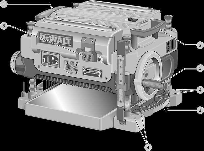
Examining the exploded view reveals the intricate arrangement of components, highlighting key parts such as the motor housing, gear assembly, and power switch. Each section is meticulously designed to contribute to the overall performance, ensuring efficiency and reliability in operation.

By studying this illustration, users can identify specific areas for troubleshooting or upgrades. It offers a clear perspective on how to approach disassembly, ensuring that reassembly is straightforward and effective. Understanding the layout not only aids in repairs but also empowers users to maximize the tool’s potential.

Replacement Parts for the DCP580 Planer

When it comes to maintaining your woodworking tool, having the right components is crucial for optimal performance and longevity. Whether you are looking to replace worn-out elements or upgrade specific features, knowing the available options can enhance your experience. This section highlights essential replacements that ensure your device operates smoothly and efficiently.

Below is a table summarizing the commonly needed components along with their functions:

Component Description
Blade Assembly Critical for achieving precise cuts, these blades are essential for effective planing.
Motor Housing Protects the internal mechanisms and provides stability to the tool during operation.
Power Switch Facilitates easy control of the machine, ensuring safety and convenience.
Depth Adjustment Knob Allows users to set the desired cutting depth, improving versatility in different tasks.
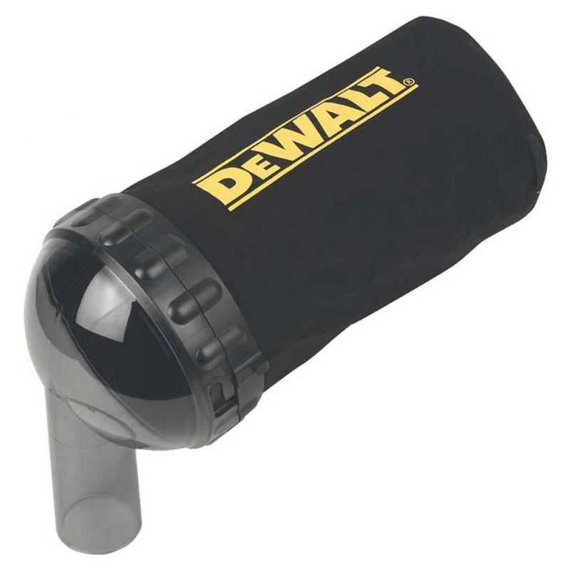
Dust Chute Helps in efficient dust collection, keeping the workspace clean and safe.

Having access to quality replacements is vital for sustaining the functionality of your tool. Regular checks and timely replacements can prevent unexpected breakdowns and maintain high efficiency.

Upgrades and Accessories for the DCP580

Enhancing the performance and functionality of your handheld sander can significantly improve your woodworking experience. By integrating various upgrades and accessories, users can tailor their tools to meet specific project needs and optimize their efficiency. Below are some recommended enhancements that can elevate your tool’s capabilities.

Popular Accessories

  • Dust Extraction Attachments: Maintaining a clean workspace is crucial. These attachments efficiently capture debris, ensuring better visibility and cleaner results.
  • Fine Grit Sanding Discs: For achieving a smooth finish on delicate surfaces, fine grit discs are essential. They provide a polished look without damaging the material.
  • Backing Pads: Upgrading to high-quality backing pads can improve the adhesion of sanding discs, providing a more stable sanding experience.

Performance Upgrades

  1. High-Performance Battery: Opting for a more powerful battery can extend runtime, allowing for longer working sessions without interruptions.
  2. Variable Speed Control: Installing a speed control feature enables users to adjust the sanding speed, catering to different materials and applications.
  3. Ergonomic Grip Enhancements: Upgrading to more comfortable grips can reduce fatigue during extended use, making tasks more enjoyable.