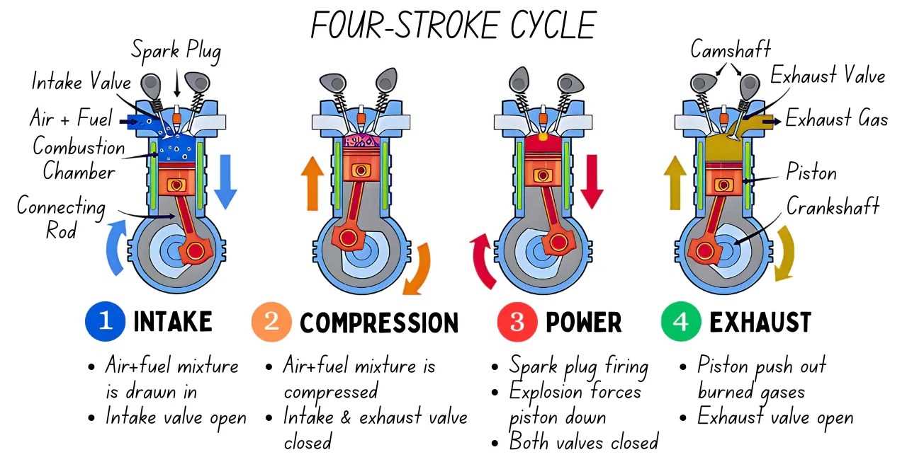
The intricate network of components that work in harmony is essential for optimal functionality in various machines. Each element plays a significant role in ensuring smooth operation, contributing to overall performance and efficiency. Grasping how these elements interact can greatly enhance one’s comprehension of mechanical systems.
By visualizing these interconnected elements, one can better appreciate their respective functions and contributions. This understanding is crucial for troubleshooting, maintenance, and enhancement of machinery. Exploring these illustrations provides valuable insights into the relationships and operations within the mechanical framework.
Whether for educational purposes or practical applications, delving into these representations enables a deeper knowledge of the inner workings of various devices. Embracing this knowledge not only fosters better skills but also inspires innovative approaches to machine management.
This section presents a comprehensive look at the essential elements that contribute to the functionality of a motor. Understanding these components is crucial for grasping how the overall mechanism operates.
Key Elements
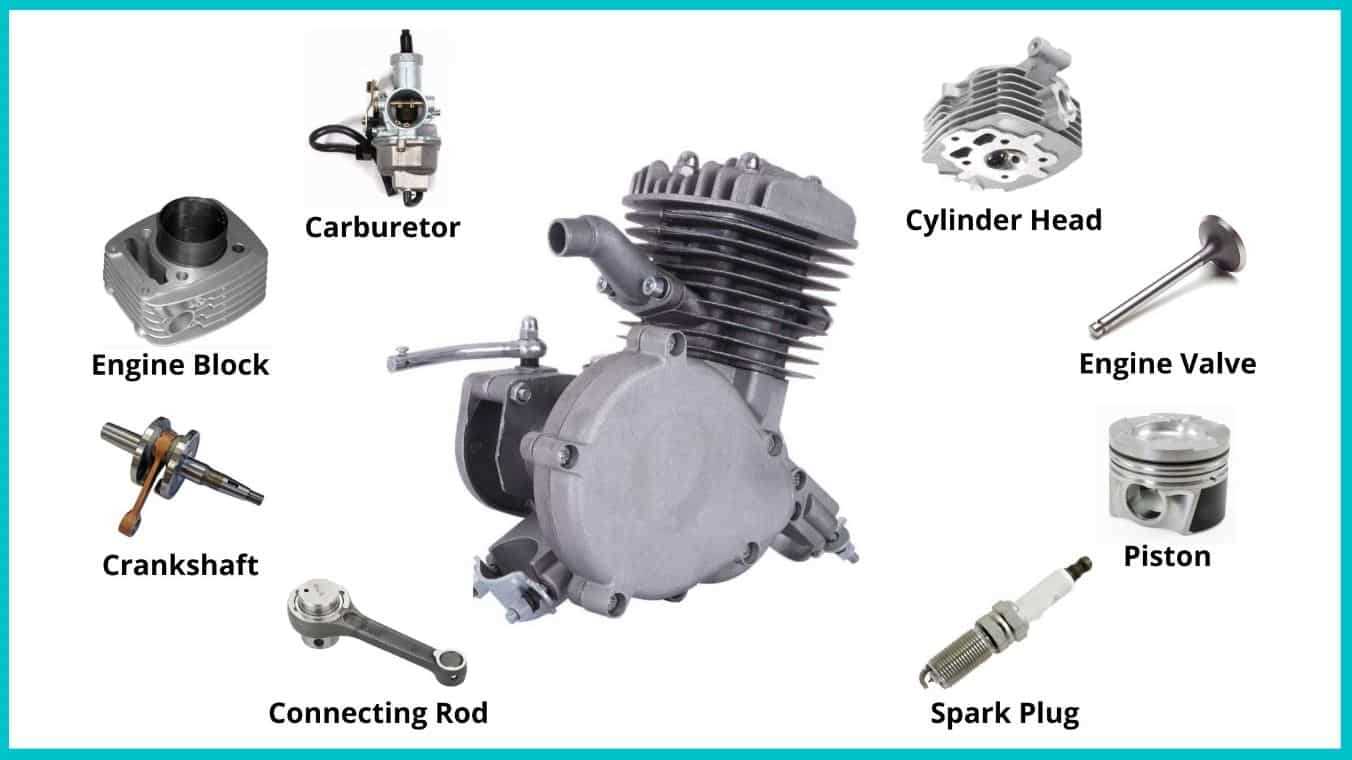
- Fuel Delivery System
- Ignition Mechanism
- Cooling System
- Lubrication Setup
- Exhaust Framework
Functionality Overview
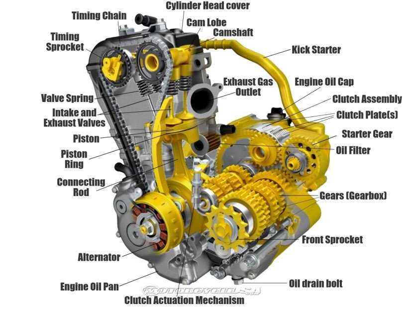
Each component plays a significant role in ensuring the smooth operation of the motor. The delivery system ensures the right mixture reaches the combustion chamber, while the ignition mechanism initiates the combustion process. Cooling and lubrication are vital for maintaining optimal operating temperatures and minimizing wear.
Understanding the interplay of these elements enhances the ability to troubleshoot and optimize performance effectively.
Types of Engine Configurations
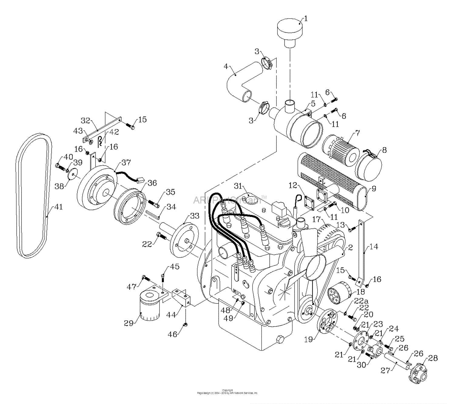
This section explores the various arrangements utilized in internal combustion systems, showcasing their distinct characteristics and applications. Each layout is engineered to optimize performance, efficiency, and compatibility with specific vehicles or machinery.
Common Configurations
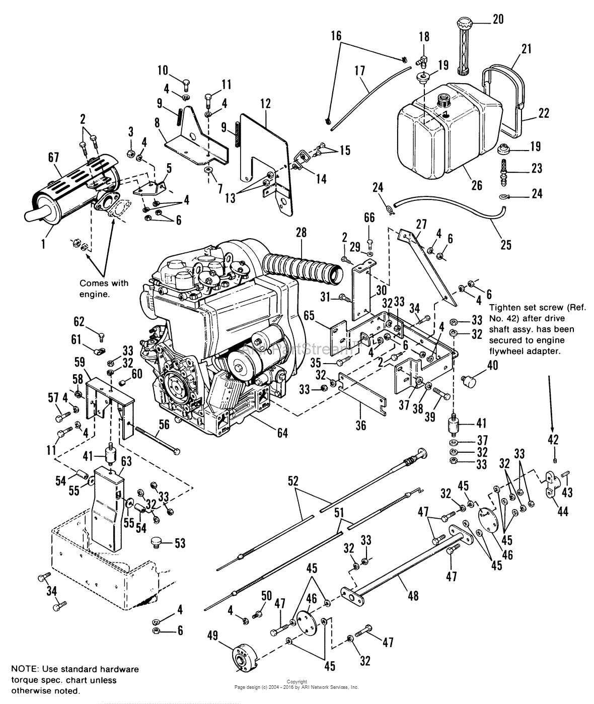
- Inline
- V-type
- Flat (Boxer)
- Rotary
Factors Influencing Choice
- Power Output
- Space Constraints
- Weight Distribution
- Maintenance Requirements
Understanding these configurations aids in selecting the most suitable system for various applications, ensuring optimal functionality and longevity.
Understanding Engine Diagrams
This section aims to clarify the visual representations used to illustrate the components of a motor system. These illustrations serve as crucial tools for both education and maintenance, providing a clear overview of how each element interacts within the larger mechanism.
Familiarizing oneself with these visuals can enhance comprehension of how various sections contribute to overall functionality. Here are some key aspects to consider:
- Components: Identifying the individual elements displayed in the visuals.
- Connections: Understanding how each segment is linked to others.
- Functionality: Recognizing the role each component plays in the system.
By mastering these representations, users can improve their ability to troubleshoot issues and perform maintenance effectively.
Key Parts and Their Functions
This section explores the essential components within a mechanical system and their respective roles. Understanding these elements is crucial for grasping how they interact to ensure optimal performance and efficiency.
Fuel Injector: This device is responsible for delivering the correct amount of fuel into the combustion chamber, ensuring efficient combustion and power generation.
Piston: The piston moves up and down within the cylinder, creating pressure that drives the crankshaft and ultimately powers the vehicle.
Crankshaft: This crucial element converts the linear motion of the pistons into rotational motion, enabling the vehicle to move.
Camshaft: It controls the timing of the valve openings and closings, allowing for optimal airflow into and out of the combustion chamber.
Exhaust System: This system expels gases produced during combustion, reducing harmful emissions and improving overall performance.
How to Read Engine Schematics
Understanding technical illustrations can enhance your ability to troubleshoot and maintain mechanical systems. These visual representations provide a clear overview of the components and their relationships within the assembly. Familiarity with the symbols and layouts used in these schematics is essential for effective interpretation.
Firstly, recognize common symbols that represent various elements. For instance, circles might indicate connections, while lines illustrate pathways for fluids or electrical currents. Understanding these symbols will allow you to quickly decipher the information conveyed.
Secondly, pay attention to the flow direction indicated in the illustrations. This can be crucial for understanding how components interact and function together. Following the flow will help you grasp the overall operation of the system more clearly.
Finally, practice by reviewing multiple examples. The more you engage with different schematics, the easier it becomes to identify patterns and nuances. Over time, you will develop the ability to read and comprehend these visuals with confidence.
Common Engine Parts Explained
This section delves into essential components found within an internal combustion mechanism, highlighting their functions and importance in ensuring optimal performance. Understanding these elements can enhance your knowledge and help with maintenance and troubleshooting.
Key Components
- Cylinder: The chamber where fuel and air mix for combustion.
- Piston: A cylindrical component that moves up and down, converting pressure into mechanical energy.
- Crankshaft: This transforms the linear motion of the piston into rotational movement, driving the vehicle.
- Camshaft: It controls the timing of valve openings and closings, facilitating airflow and exhaust expulsion.
Supporting Elements
- Valves: Regulate the intake of air-fuel mixture and the expulsion of exhaust gases.
- Fuel Injector: Introduces the fuel into the combustion chamber, ensuring efficient mixing.
- Cooling System: Maintains optimal temperature, preventing overheating during operation.
- Ignition System: Initiates combustion through electric sparks, crucial for engine start-up.
Importance of Accurate Diagrams
Accurate representations play a crucial role in understanding complex systems. They serve as essential tools for technicians and engineers, providing clarity and precision in visualizing components and their relationships. This clarity is vital for effective troubleshooting, maintenance, and assembly processes.
Enhancing Communication
Clear illustrations foster better communication among team members. When everyone can refer to the same visual reference, misunderstandings are minimized, and collaboration is streamlined. This uniformity is particularly beneficial in training scenarios, where newcomers can quickly grasp the intricacies of the system.
Facilitating Efficient Repairs
Detailed representations significantly improve the efficiency of repair work. Technicians can easily identify the location and function of various elements, enabling them to diagnose issues more swiftly. This leads to reduced downtime and enhanced productivity, ultimately benefiting overall operational performance.
Maintenance Tips for Engine Parts
Proper care of internal mechanisms is essential for optimal performance and longevity. Regular maintenance not only enhances functionality but also prevents costly repairs down the line.
- Inspect lubricants regularly to ensure they are clean and at appropriate levels.
- Replace filters periodically to prevent contaminants from affecting performance.
- Check for any signs of wear or damage and address issues promptly.
- Ensure all connections are secure to avoid leaks and inefficiencies.
Following these guidelines will help maintain the overall health of your machinery, ensuring it runs smoothly and efficiently.
Diagnosing Issues with Diagrams
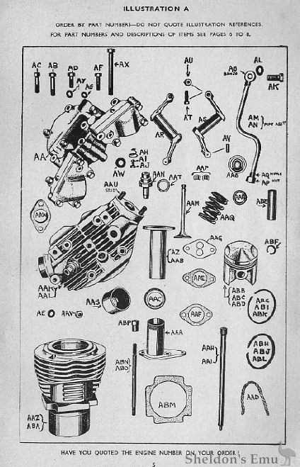
Understanding complex machinery can often be challenging, but visual representations play a crucial role in simplifying this task. By utilizing these illustrations, individuals can easily identify components and their interactions, facilitating more effective troubleshooting processes. This section explores how these visual aids assist in diagnosing mechanical failures and optimizing functionality.
Identifying Common Problems
Visual guides can help pinpoint frequent issues encountered in mechanical systems. By studying these representations, users can recognize symptoms of malfunctions, such as unusual noises or performance drops, leading to more accurate assessments. This proactive approach not only saves time but also minimizes the risk of further complications.
Enhancing Repair Techniques
With a clear visual reference, technicians can improve their repair strategies. Detailed representations allow for better planning and execution of maintenance tasks, ensuring that the right actions are taken at the right time. This methodical approach reduces the likelihood of overlooking critical aspects, ultimately enhancing the overall reliability of the system.
Visualizing Engine Assembly Process
This section aims to illustrate the intricate procedure involved in the construction of a power unit, emphasizing the various stages and their significance. By understanding the sequential steps, one can appreciate the complexity and precision required for assembling these mechanisms.
Key Stages in Assembly
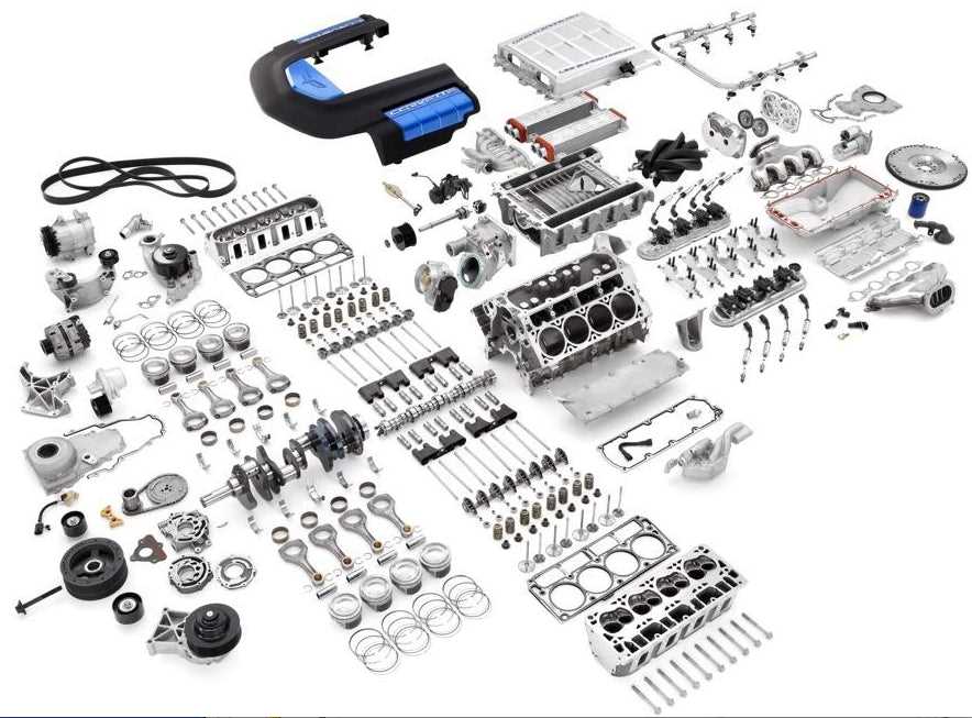
Initially, the framework is set up, ensuring all components fit together seamlessly. Subsequent phases involve integrating crucial elements, such as the core functionality and auxiliary systems, which enhance overall performance.
Importance of Visualization

Employing visual aids in this process enables technicians to pinpoint potential issues and optimize workflows. By recognizing relationships among components, assembly can be executed with greater efficiency and accuracy, ultimately leading to a more reliable operation.
Resources for Engine Diagrams
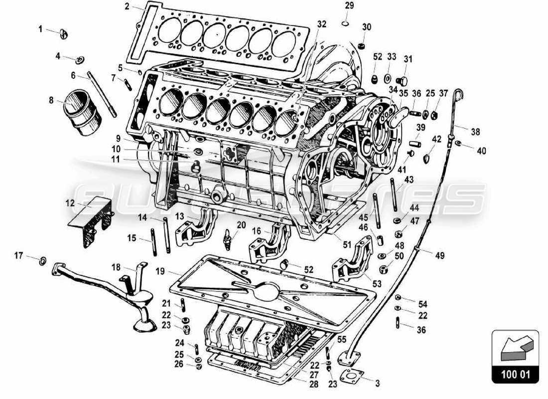
Accessing quality materials for understanding machinery layouts is essential for enthusiasts and professionals alike. These resources provide valuable insights and detailed visuals, enhancing comprehension of complex systems.
Online Libraries: Numerous digital platforms host comprehensive collections of technical illustrations, enabling users to explore a wide variety of machinery configurations.
Manuals and Guides: Official documentation from manufacturers often includes thorough visuals, offering precise information on the arrangement and functionality of various components.
Forums and Communities: Engaging with specialized online groups can lead to shared resources and insights, as members frequently exchange diagrams and explanations.
Educational Websites: Many platforms dedicate themselves to technical education, featuring tutorials and detailed visuals that clarify the inner workings of mechanical systems.
Utilizing these resources can significantly enhance one’s understanding of machinery design and operation.