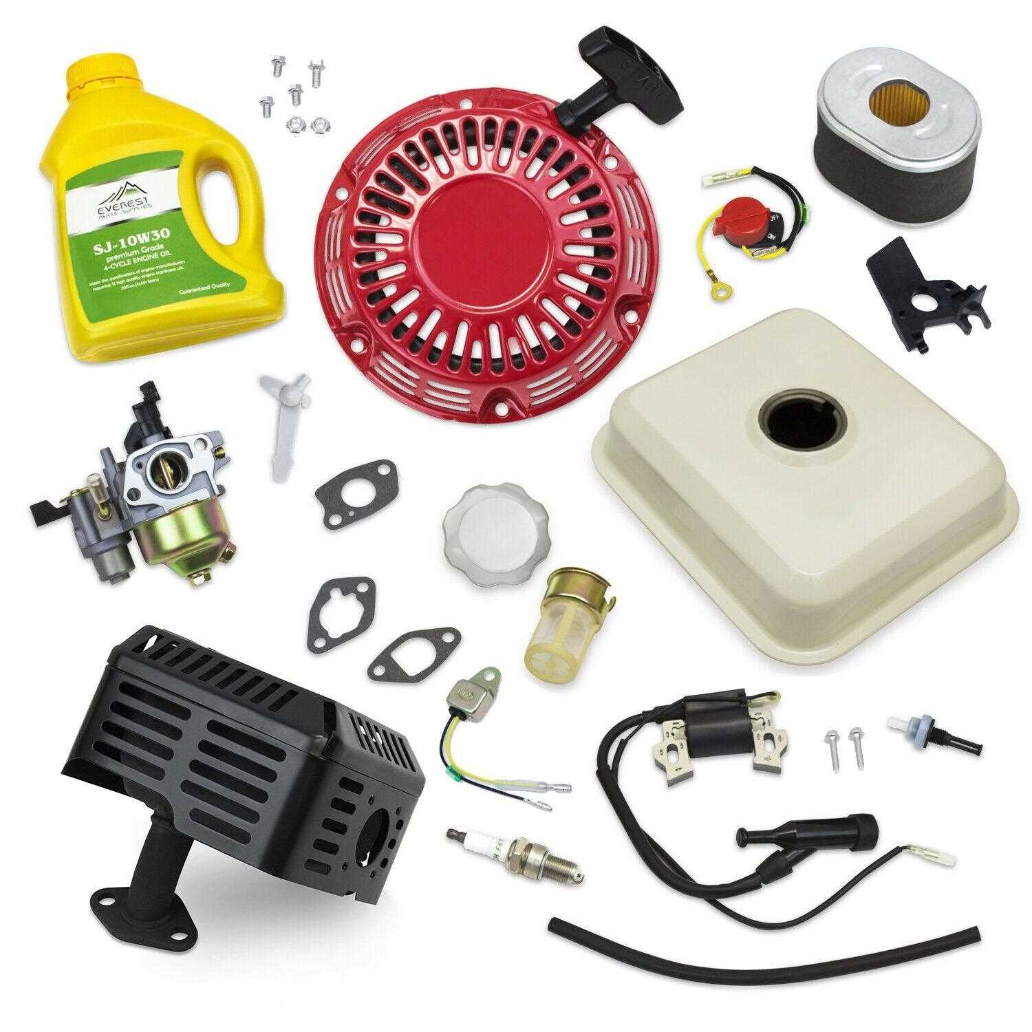
In the world of small machinery, certain power units have gained widespread use due to their reliability and performance. One specific model has become especially well-regarded in various industries, from agriculture to construction. It stands out for its versatility and capability to handle different tasks with ease. This section delves into the essential components and structure of this efficient power source, helping users understand its assembly and functionality better.
A clear understanding of how the different elements of this machine come together can significantly enhance maintenance and repair efforts. Knowing the layout of the components ensures smoother troubleshooting, allowing for quicker identification of potential issues. Whether you are an experienced technician or a newcomer to such machinery, this guide will serve as a valuable resource in exploring the intricate design and arrangement of this trusted power unit.
Overview of the GX160 5.5 HP Engine
The power system in question is widely known for its reliability and efficiency. This compact yet robust mechanical solution is used across various applications, providing steady and consistent performance. Its design ensures that it can handle demanding tasks while maintaining fuel efficiency, making it a popular choice in numerous industries. The build quality and durable materials contribute to its long service life.
Main Features
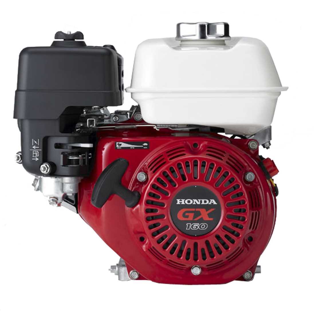
This system boasts several key characteristics that make it stand out. These include an overhead valve structure, which enhances both performance and longevity. Additionally, the cooling mechanism helps prevent overheating during extended use, ensuring continuous operation. The design also incorporates a reliable ignition setup, allowing for smooth startups even in challenging conditions
Main Components of the Honda GX160
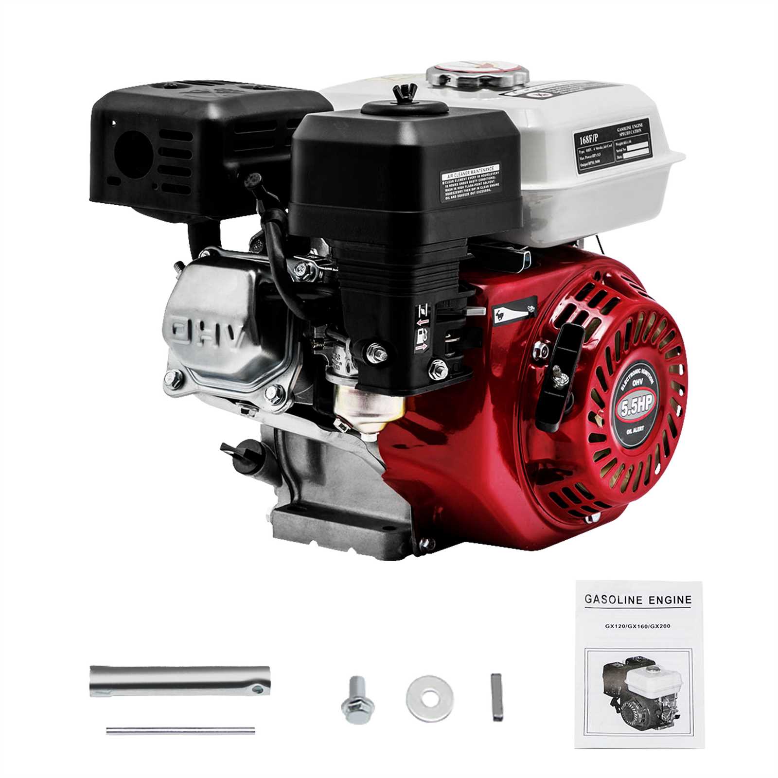
The internal structure of this power unit is comprised of several critical elements, each playing a specific role in ensuring smooth and efficient operation. These components are designed to work in harmony, allowing the device to function under various conditions while maintaining performance and reliability. Below, we will explore the key parts that contribute to the core functionality of this machinery.
Key Mechanical Parts
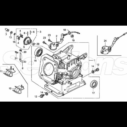
The core mechanics include elements that directly handle the movement and energy transfer within the unit. These mechanical parts are essential for the overall motion and power output of the system. Without these, the device would not be able to perform its intended tasks.
Other Essential Components
Aside from mechanical elements, there are other
Internal Mechanics of the GX160 Engine
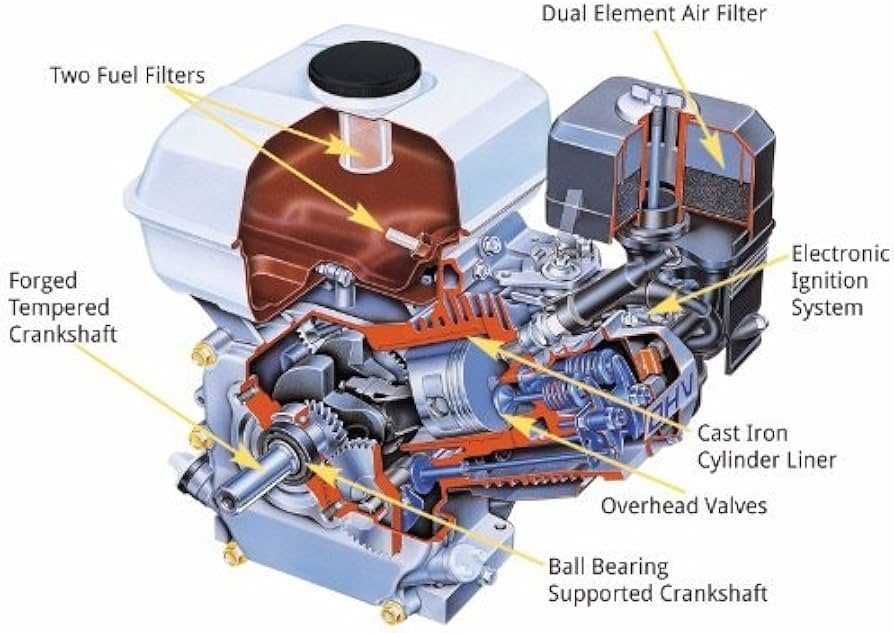
The core structure of this small power unit operates through a series of interlocking components that transform energy into mechanical force. Each part within the system works in precise harmony to achieve efficiency and reliability. Understanding the internal mechanisms helps to maintain and troubleshoot this machinery effectively.
- Piston and Cylinder: The primary motion in this power unit is generated by the piston moving within the cylinder. This back-and-forth movement compresses air and fuel, creating the necessary force for power output.
- Crankshaft: Connected to the piston via a connecting rod, the crankshaft transforms the linear motion of the piston into rotational energy. This motion is crucial for driving the various systems within the machinery.
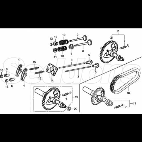
- Camshaft and Valves: The camshaft controls the opening and closing of intake and exhaust valves. Proper timing of this mechanism ensures the smooth operation of the combustion process.
- Flywheel: Serving as a balancing mechanism, the flywheel stores energy during operation and helps maintain steady performance, reducing fluctuations in power output.
- Carburetor: This component mixes fuel with air in the correct proportions, ensuring that combustion is both efficient and effective.
By examining these essential parts, one can better understand the operation of this compact and powerful system, as well as identify any issues that may arise during use.
Ignition System and Operation
The ignition mechanism plays a crucial role in ensuring smooth and efficient functioning of internal combustion machines. This system is responsible for initiating the spark that ignites the fuel-air mixture, leading to the power needed for the machine’s operation. By generating a controlled spark at precise intervals, it ensures optimal performance and contributes to the overall reliability of the machinery.
The ignition process involves several components working in unison, such as a coil, spark plug, and flywheel. These parts collaborate to convert mechanical energy into the necessary electrical current, which then ignites the fuel. Proper maintenance of these elements is essential for reliable operation, ensuring that the ignition happens consistently without delay or misfire.
Additionally, understanding how the ignition works can help troubleshoot potential issues like delayed starts, poor acceleration, or misfires. Regular inspection and replacement of key components, such as the spark plug and ignition coil, can significantly improve performance and prolong the life of the machinery.
Fuel System Breakdown
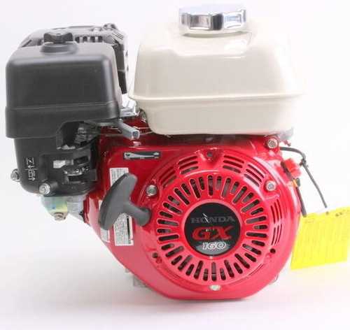
The fuel system is a vital component responsible for delivering the correct mixture of fuel and air to the combustion chamber. Understanding the breakdown of this system helps in identifying the essential elements that ensure optimal performance and efficiency. Proper maintenance and regular inspection can prevent common issues, such as clogs or leaks, which may affect overall functionality.
Key elements of the fuel system include the fuel tank, filters, lines, and the carburetor. Each of these parts plays a significant role in controlling the flow and quality of fuel delivered. For instance, the fuel tank stores the gasoline, while the filters ensure only clean fuel reaches the combustion chamber. The lines transport the fuel to the carburetor, where the air-fuel mixture is prepared for ignition.
Regular attention to these components can help maintain the efficiency of the machine. Inspecting the fuel lines for cracks, replacing old filters, and ensuring the carburetor is clean are key steps in preventing malfunctions. Proper upkeep of the fuel system guarantees smooth operation and long-term reliability.
Understanding the Carburetor Structure
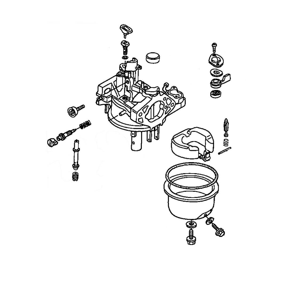
The carburetor is a vital component of many combustion systems, playing a key role in the process of mixing air and fuel. Its design ensures that the correct ratio of these elements is delivered to the combustion chamber, thereby enhancing performance and efficiency. A well-functioning carburetor can significantly affect the overall operation of the machinery it serves.
Typically, the carburetor comprises several essential parts, each contributing to its functionality. Understanding these components helps in troubleshooting and maintenance, ensuring that the system operates smoothly. Below is a table summarizing the main components of a typical carburetor along with their functions:
| Component | Function |
|---|---|
| Float Chamber | Maintains a constant fuel level for consistent operation. |
| Venturi | Creates a vacuum that draws fuel into the airflow. |
| Jet | Controls the amount of fuel entering the airstream. |
| Throttle Valve | Regulates the airflow, impacting the power output. |
| Choke Valve | Reduces air intake for easier starting in cold conditions. |
Each part plays a crucial role in ensuring that the carburetor functions correctly, impacting the overall performance of the machine. Proper understanding and maintenance of these components can lead to enhanced efficiency and longevity of the system.
Exhaust System Layout
The exhaust system is a crucial component that manages the expulsion of gases generated during the combustion process. It plays a significant role in enhancing the overall efficiency and performance of the machine. Proper configuration of this system ensures optimal flow of exhaust gases, minimizing back pressure and facilitating smoother operation.
Components of the Exhaust System
Typically, the exhaust system consists of several key elements that work in unison. These include the manifold, which collects exhaust gases from the combustion chamber, and the muffler, designed to reduce noise levels while allowing gases to exit freely. Additionally, the piping that connects these components is essential for maintaining the correct flow dynamics.
Importance of Proper Maintenance
Regular maintenance of the exhaust layout is vital for sustaining the performance of the machinery. Checking for leaks, corrosion, and blockages can prevent potential issues that may arise from inefficient gas expulsion. Ensuring that all components are securely fitted and in good condition will contribute to the longevity and reliability of the entire system.
Cooling Mechanism and Parts
The cooling system is vital for maintaining optimal operating temperatures in machinery, ensuring efficient performance and longevity. Proper temperature regulation prevents overheating, which can lead to mechanical failure and decreased efficiency. Understanding the components involved in this system is essential for effective maintenance and troubleshooting.
Key Components of the Cooling System
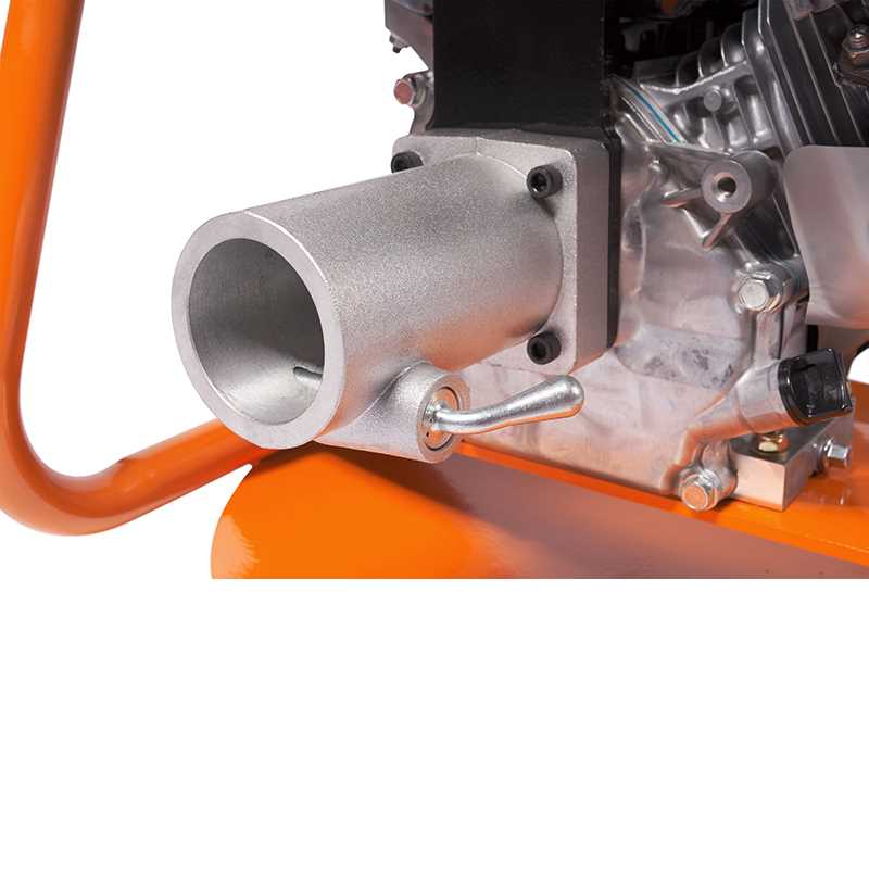
The primary elements of a cooling mechanism include the cooling fan, radiator, and cooling fins. The cooling fan plays a crucial role by circulating air around the system, enhancing heat dissipation. Additionally, the radiator serves to transfer heat away from the machine, while the cooling fins increase surface area, allowing for more efficient heat exchange.
Maintenance and Troubleshooting
Regular maintenance of the cooling components is essential for optimal performance. This includes checking for blockages, ensuring the fan operates correctly, and inspecting the radiator for leaks. Routine cleaning can prevent overheating and ensure that the system functions smoothly, prolonging the lifespan of the machinery.
Honda GX160 Maintenance Tips
Proper upkeep of your small motor can greatly enhance its performance and longevity. Regular maintenance ensures that the machine runs efficiently and reduces the risk of unexpected breakdowns. By following a few essential guidelines, you can keep your equipment in top shape, maximizing its reliability and functionality.
Regular Inspection
- Check the oil level frequently and change it according to the manufacturer’s recommendations.
- Inspect the air filter for dirt and debris, replacing it when necessary to ensure optimal airflow.
- Examine the spark plug for wear; clean or replace it if the electrode is damaged or fouled.
Fuel Management
- Use fresh, high-quality fuel to avoid starting issues and to maintain engine health.
- Drain the fuel system before long periods of inactivity to prevent varnish buildup.
- Add a fuel stabilizer to prolong the shelf life of gasoline.
Common Issues and Troubleshooting
When working with small machinery, users may encounter various complications that can hinder performance. Understanding typical problems and their solutions can significantly enhance the reliability and longevity of the device. This section aims to identify frequent issues and provide practical troubleshooting steps.
- Difficulty Starting:
If the machinery does not start, check the following:
- Ensure that there is enough fuel in the tank.
- Inspect the ignition system for any faults or wear.
- Verify that the choke is in the correct position.
- Overheating:
Excessive heat can lead to serious damage. To address this, consider:
- Checking for blocked air vents or cooling fins.
- Ensuring the oil level is adequate and the oil is clean.
- Inspecting the fuel quality and ensuring it meets specifications.
- Loss of Power:
A sudden decrease in output may indicate several issues. Potential causes include:
- Clogged air filters or fuel lines.
- Worn-out spark plugs that need replacement.
- Improper adjustments to the carburetor settings.
- Unusual Noises:
Strange sounds can signal underlying problems. Take the following actions:
- Listen for rattling or grinding noises and check for loose components.
- Examine the belts and bearings for wear or damage.
- Consult the manual for any recommended maintenance routines.
By following these guidelines, users can effectively troubleshoot and resolve common issues, ensuring the smooth operation of their machinery.
Assembly and Disassembly Guide
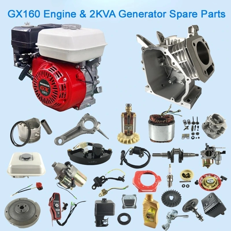
This section provides a comprehensive overview of the processes involved in assembling and disassembling a small power unit. Proper techniques are crucial to ensure efficient operation and longevity of the device. Understanding the components and their interactions will aid in maintenance and repairs.
To begin the disassembly, ensure that the unit is powered off and completely cool. Remove any protective coverings or casings to expose the internal mechanisms. Take care to document the order of removal, as this will simplify the reassembly process. Use appropriate tools to avoid damaging screws or connections.
During the disassembly, pay attention to specific components that may require special handling. Gaskets, seals, and other small parts should be stored in a labeled container to prevent loss. Inspect each piece for wear and tear, as this will inform you of any necessary replacements during reassembly.
For the assembly phase, start by placing the main components in their designated positions, ensuring that all fittings are aligned correctly. Reinstall any seals and gaskets to prevent leaks, and tighten screws to the recommended specifications. A systematic approach will help ensure that all parts are reconnected properly and that the unit operates as intended.
Once assembly is complete, conduct a thorough inspection before powering on the device. Check for any loose connections or misaligned components. Following these guidelines will facilitate a smooth assembly and disassembly process, enhancing the functionality and lifespan of your power unit.