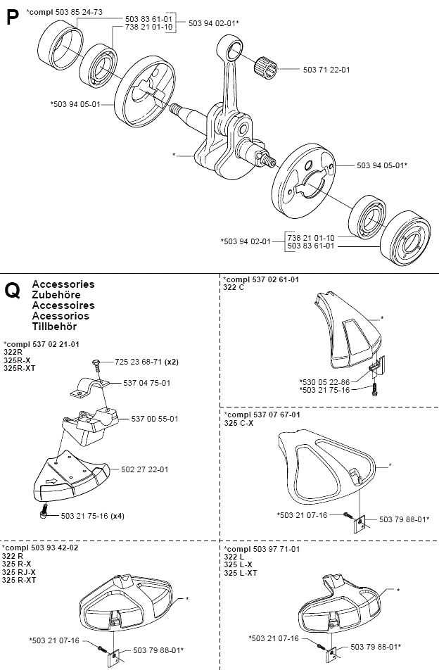
When working with mechanical devices, having a clear view of the internal structure is essential for proper upkeep. This section focuses on offering insight into how the various elements come together to ensure smooth operation. A well-organized blueprint of these elements simplifies the process of locating key elements and allows for efficient repairs and replacements when necessary.
Knowing the arrangement of individual elements not only helps with identifying potential issues but also enhances overall equipment longevity. By understanding how each piece fits into the larger system, one can prevent unnecessary wear and maintain functionality over time.
Whether you’re dealing with common issues or more complex malfunctions, having a detailed layout at hand provides a clearer path toward resolving problems. Recognizing the roles of different components ensures that you can address the right areas, making maintenance less of a hassle and improving performance in the long run.
Essential Components of the Husqvarna 322C
The machine is built with a collection of key elements that ensure its efficient functionality. Each part plays a critical role in maintaining the overall performance, contributing to durability and smooth operation. Understanding these components helps in maximizing the tool’s lifespan and effectiveness during use.
Engine Assembly is the heart of the device, delivering the necessary power to drive its operations. This core section requires proper maintenance for consistent and reliable performance over time.
Cutting Mechanism consists of sharp, durable blades designed for precision and efficiency. Regular inspection of this part ensures a clean and accurate operation in various tasks.
Fuel and Air System manages the mixture of fuel and air to ensure optimal combustion. Proper tuning of this system improves the energy output and reduces waste, enhancing operational efficiency.
Engine System Breakdown and Analysis
The engine system is the core component that drives the operation of most mechanical equipment, ensuring efficiency and performance. Understanding the breakdown of this system allows for better maintenance, troubleshooting, and optimization of overall functionality. In this section, we will analyze the key elements that make up the engine, how they interact, and the role they play in powering the entire system.
Main Components of the Engine
- Cylinder and Piston: The cylinder houses the piston, which moves up and down, generating the mechanical energy needed for operation.
- Crankshaft: Connected to the piston, the crankshaft converts the linear motion into rotational force, powering other parts of the system.
- Carburetor: Responsible for mixing air and fuel in the
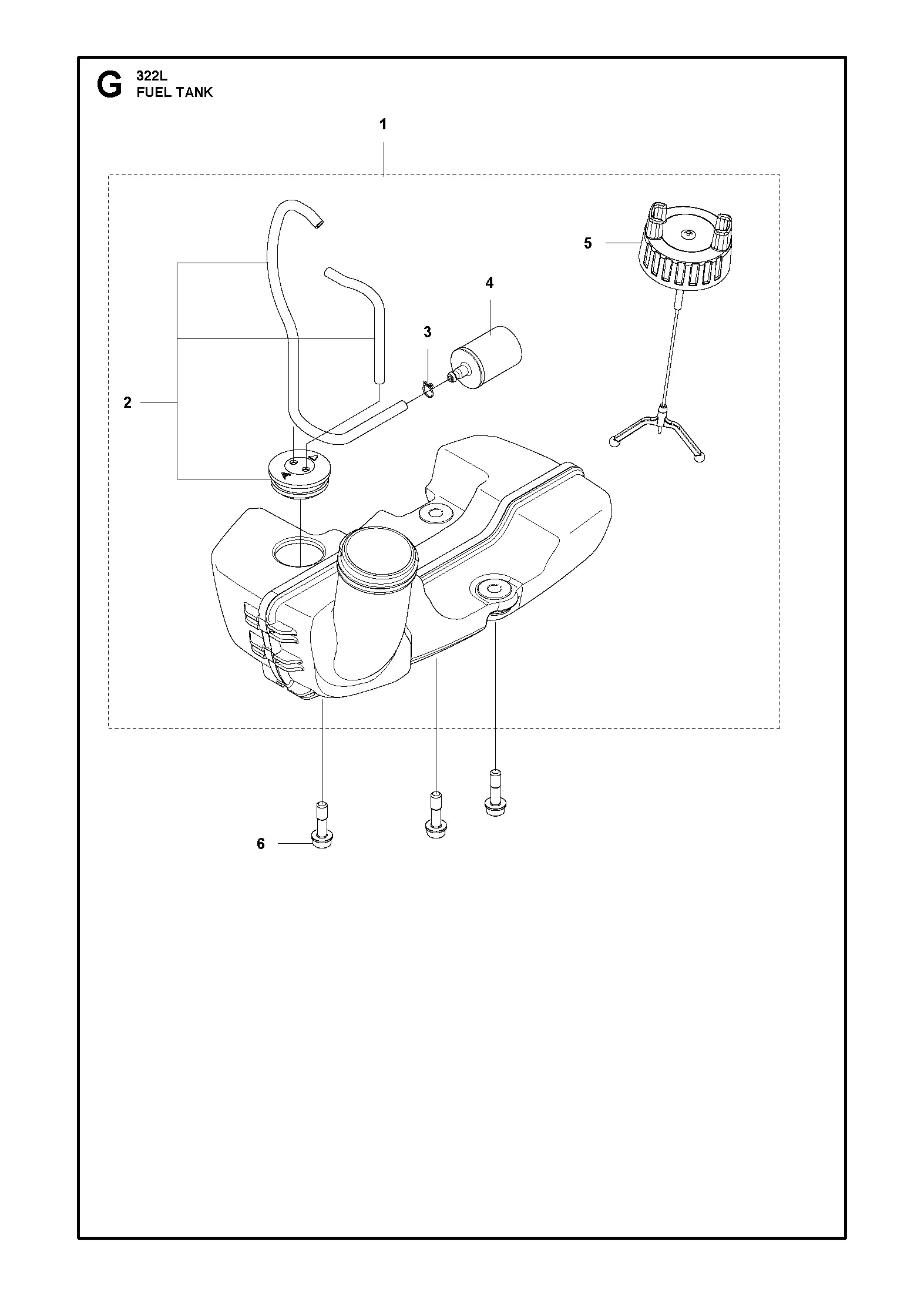
Fuel Tank and Line Configuration
The design of the fuel system plays a crucial role in ensuring efficient engine performance. A well-structured configuration is essential for the smooth flow of fuel from the tank to the engine, minimizing any interruptions during operation. The tank itself needs to be securely mounted and properly vented to maintain optimal pressure, while the lines must be routed to avoid blockages or leaks.
Proper alignment of the fuel lines ensures that fuel is delivered consistently. Using durable, high-quality materials for both the tank and the lines enhances longevity and prevents wear over time. It is important to check regularly for any signs of wear or damage in the fuel system to prevent potential malfunctions.
Maintenance and inspection of these components are key to keeping the system functioning properly. Keeping the connections tight and free from debris will help avoid any disruptions in fuel supply, ensuring steady performance.
Cutting Head Structure and Maintenance
The design of the cutting head is a critical aspect of achieving effective trimming performance. Its components are engineered to ensure smooth operation and precision. Regular maintenance is necessary to sustain optimal functionality and extend the longevity of the tool. Below is an overview of the key components and some practical steps for maintaining the cutting head to keep it in excellent working condition.
Main Components
Component Description Spool Holds the line and ensures smooth unwinding during operation. Cover Protects internal parts from debris and secures the line in place. Spring Provides tension for the automatic line release mechanism. Clutch Mechanism and Drive Shaft Overview
The interaction between the clutch mechanism and the drive shaft is vital to ensuring smooth operation and efficient power transmission. Understanding how these components work together can significantly improve maintenance and troubleshooting of the system. The clutch engages and disengages the power flow, while the drive shaft transfers this energy to the working parts of the machine, ensuring performance and stability.
Clutch Mechanism Functionality
The clutch operates as a pivotal element for controlling the rotational force. It allows the operator to
Handle Assembly and Control Features
The handle assembly plays a crucial role in the overall functionality and user experience of outdoor equipment. It is designed to provide comfort and control, enabling operators to maneuver the device effectively while minimizing fatigue. Understanding the various components and their configurations is essential for optimal operation.
At the core of the handle assembly are the grips, which are ergonomically shaped to enhance comfort during extended use. These grips often feature materials that provide a non-slip surface, ensuring a secure hold even in wet conditions. Additionally, the positioning of controls such as the throttle and stop switch is strategically placed for easy access, allowing users to adjust settings without losing grip.
Moreover, the assembly may include adjustable features, enabling users to customize the height and angle of the handle to suit their preferences. This adjustability not only contributes to improved ergonomics but also enhances maneuverability, allowing for precise handling in various environments.
In summary, the design and functionality of the handle assembly, coupled with thoughtfully placed control features, significantly enhance the usability and comfort of outdoor equipment, making it easier to operate efficiently and effectively.
Air Filter Setup and Replacement Guide
Maintaining optimal performance in outdoor power equipment is essential for longevity and efficiency. One crucial component that often requires attention is the air filtration system. Proper setup and timely replacement of the air filter ensure that the engine operates smoothly and prevents contaminants from affecting its functionality.
Follow this guide to effectively set up and replace the air filter in your equipment:
- Gather Necessary Tools:
- Replacement air filter
- Screwdriver (if applicable)
- Clean cloth or brush
- Safety gloves
- Locate the Air Filter:
Identify the location of the air filter, usually situated near the engine. Refer to the user manual for specific guidance on your model.
- Remove the Cover:
If applicable, use the screwdriver to detach the cover protecting the air filter. Keep the screws in a safe place.
- Inspect the Old Filter:
Examine the existing filter for dirt and damage. If it appears clogged or worn, it’s time for a replacement.
- Install the New Filter:
Place the new air filter in the designated slot, ensuring a snug fit. Make sure it aligns correctly to prevent air leaks.
- Reattach the Cover:
Secure the cover back in place, tightening any screws to keep the filter protected.
- Test the Equipment:
Start the engine to ensure it runs smoothly. Listen for any unusual sounds that may indicate improper installation.
Regular maintenance of the air filtration system not only enhances performance but also prolongs the life of your equipment. Always consult your user manual for specific instructions regarding your model to ensure proper care.
Starter Mechanism and Ignition System
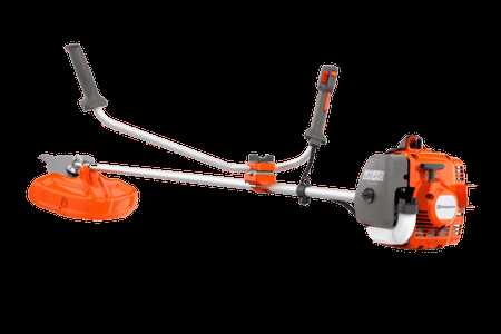
The starter mechanism and ignition system are vital components in the operation of outdoor power equipment. These systems work in tandem to ensure that the engine starts reliably and operates smoothly. Understanding the functionality and components of these systems can aid in troubleshooting and maintenance, enhancing the overall performance of the machine.
Components of the Starter Mechanism
- Starter Rope: This is typically a pull cord that initiates the engine’s operation when pulled.
- Recoil Starter: A spring-loaded device that retracts the starter rope after it has been pulled, allowing for easy starting.
- Flywheel: This component rotates when the starter rope is pulled, engaging the engine’s ignition process.
- Starter Motor: In some models, an electric motor is used to crank the engine, reducing manual effort.
Ignition System Functionality
- Ignition Coil: This device transforms low battery voltage into a high-voltage spark necessary for ignition.
- Spark Plug: The spark plug ignites the fuel-air mixture in the combustion chamber, enabling the engine to run.
- Flywheel Magnet: A magnet attached to the flywheel generates a magnetic field that triggers the ignition coil.
- Timing Mechanism: Ensures that the spark occurs at the optimal moment for effective combustion.
Regular maintenance of the starter mechanism and ignition system is crucial for reliable performance. Checking components for wear and ensuring proper alignment can significantly extend the lifespan of the equipment.
Vibration Dampening System Parts
The effectiveness of a vibration dampening system is crucial for enhancing user comfort and equipment longevity. This system is designed to minimize the transmission of vibrations generated during operation, ensuring smoother functionality and reducing operator fatigue. Understanding the components that contribute to this system is essential for maintenance and troubleshooting.
Key Components of the Dampening System
At the core of the vibration reduction mechanism are several integral elements. These include isolators that absorb shocks, mounts that provide stability, and rubber buffers that mitigate excessive oscillations. Each component works in tandem to create a harmonious balance between performance and comfort.
Maintenance Considerations
Regular inspection of the dampening system is necessary to ensure optimal performance. Wear and tear on components can lead to diminished effectiveness, causing increased vibrations. Replacing damaged parts promptly is essential to maintaining both efficiency and user satisfaction.
Protective Cover and Guard Elements
The protective components of outdoor equipment play a crucial role in ensuring user safety and maintaining optimal performance. These elements are designed to shield the operational parts of the machine from debris, accidental contact, and potential hazards. A thorough understanding of their function and placement is essential for effective maintenance and safe operation.
Functionality of Protective Covers
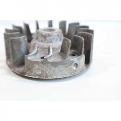
Protective covers are integral to safeguarding the machinery from external elements, such as dirt and moisture, which can lead to wear and tear. These covers also help in minimizing the risk of injuries by preventing direct access to moving parts during operation. Properly installed, they enhance the longevity of the equipment while providing peace of mind to the user.
Guard Elements and Safety Standards
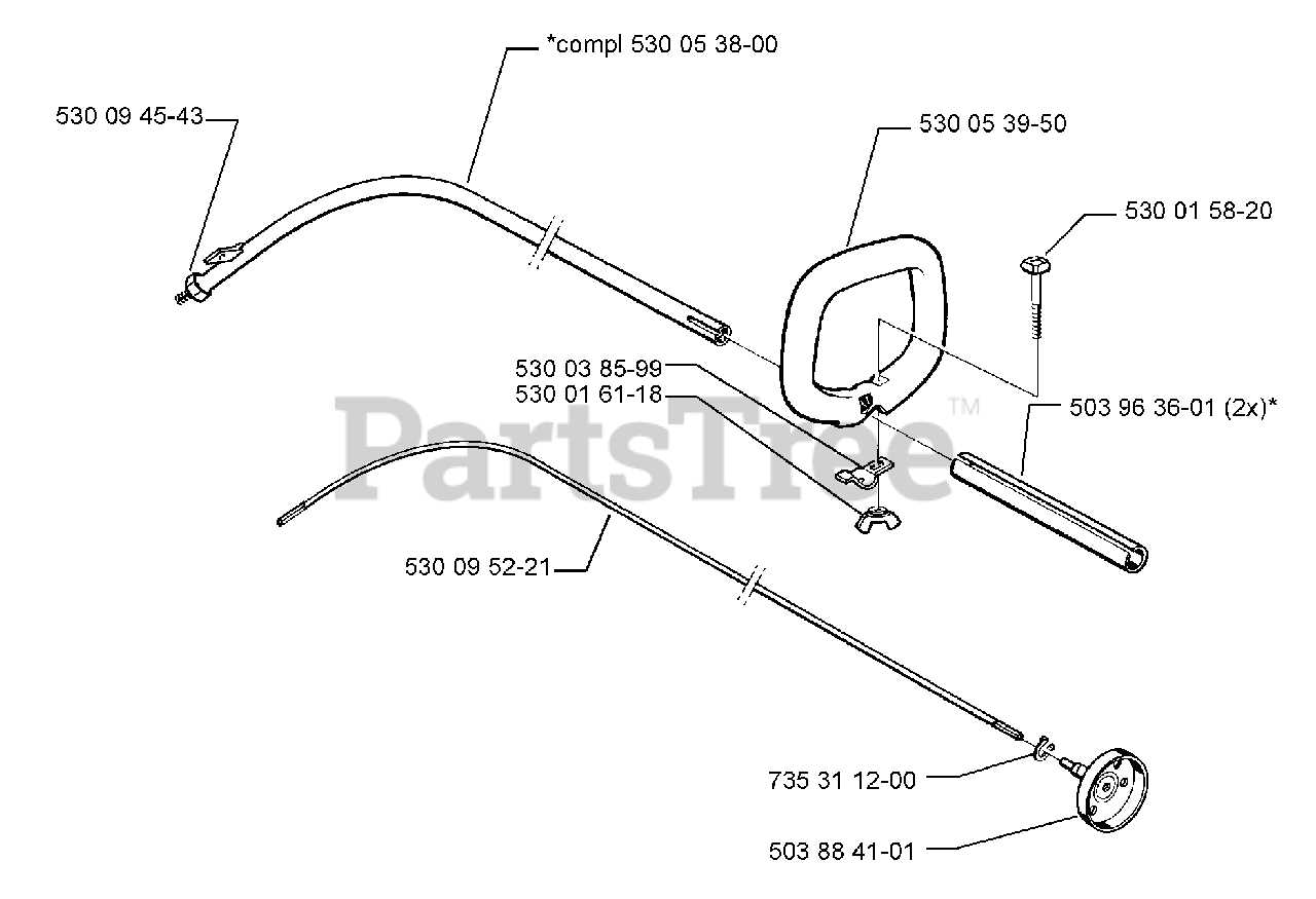
Guard elements are specifically engineered to comply with safety standards, ensuring that all operational aspects are enclosed or shielded. Their design focuses on preventing accidental contact with hazardous parts, thus reducing the likelihood of accidents. Regular inspection and maintenance of these components are vital to ensure that they remain effective in protecting users and extending the lifespan of the equipment.
Blade Attachment and Adjustment Process
Proper installation and calibration of the cutting implement are essential for achieving optimal performance in outdoor equipment. This section outlines the steps involved in securely attaching the blade and ensuring it is correctly adjusted for effective operation.
Step 1: Gather Necessary Tools
Before beginning the attachment process, collect all required tools, including a wrench, screwdriver, and safety gear. Ensuring that everything is within reach will facilitate a smoother workflow.
Step 2: Prepare the Equipment
Ensure that the machine is powered off and has cooled down. This precaution helps to prevent any accidents or injuries while handling the components. It is advisable to work in a well-lit area to enhance visibility during the installation.
Step 3: Attach the Cutting Implement
Align the cutting tool with the mounting points on the equipment. Insert the blade into the designated slot and secure it using the fastening mechanisms provided. Make sure the blade is seated firmly to avoid any risks of detachment during operation.
Step 4: Adjust the Blade Position
Once attached, check the alignment of the blade. It should be parallel to the ground for even cutting. Use a level to confirm that the blade is properly positioned. If necessary, make adjustments by loosening the securing bolts and repositioning the implement before tightening them again.
Step 5: Test the Setup
After installation, conduct a brief test run. Observe the cutting implement in action to ensure it operates smoothly and efficiently. Any unusual vibrations or sounds may indicate improper attachment or adjustment, requiring immediate attention.
Conclusion
Following these steps will help ensure that the cutting tool is correctly attached and adjusted, maximizing performance and safety. Regular maintenance checks are also recommended to maintain optimal functionality over time.
- Gather Necessary Tools: