Assists in reducing steering effort, providing
Fuel System Layout
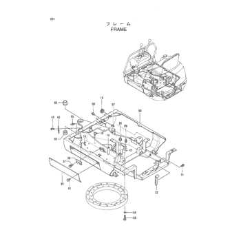
The configuration of the fuel delivery system is crucial for optimal engine performance. This layout typically involves several components working together to ensure efficient fuel flow and combustion. Understanding how these elements interact can help in maintaining and troubleshooting the overall system.
Key Components
At the heart of the fuel system are the tank, pump, and carburetor. The fuel tank stores the liquid, while the pump is responsible for transporting it to the engine. The carburetor mixes the fuel with air to create a combustible mixture, which is essential for starting and running the engine smoothly.
System Functionality
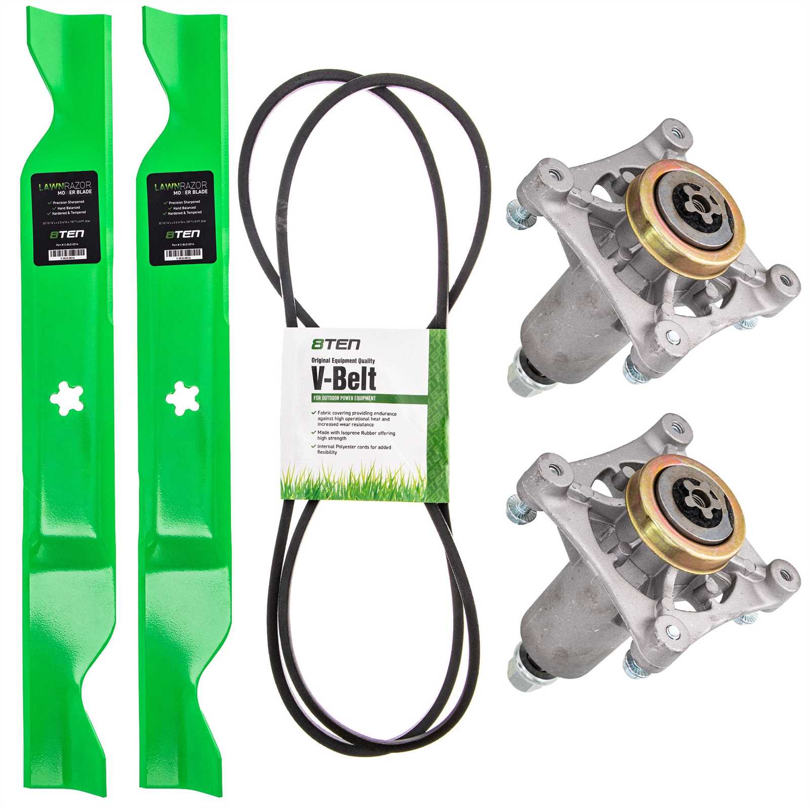
The layout of the fuel system is designed to facilitate a seamless flow of fuel from the tank to the engine. Gravity or mechanical pumps often assist in this process, ensuring that the right amount of fuel reaches the combustion chamber. Regular inspection and maintenance of these components are vital to prevent issues such as leaks or blockages that can hinder performance.
Electrical Wiring Map
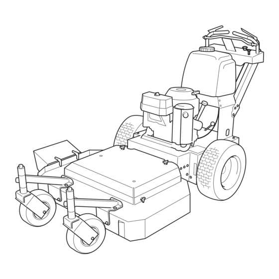
The electrical wiring map serves as a crucial reference for understanding the connections within the system. It illustrates the arrangement of electrical components, providing insights into their interactions and functions. This visual guide aids in troubleshooting and repairs, ensuring that each element is correctly linked for optimal performance.
Each wire and connector is typically labeled, indicating its purpose and destination. Familiarity with this schematic is essential for anyone involved in maintenance or repairs, as it allows for quick identification of potential issues and simplifies the process of resolving them. By following the layout presented, technicians can systematically approach any electrical challenges that may arise.
Transmission Unit Breakdown
The transmission system is a crucial component in the operation of any machinery that relies on movement. It is responsible for transferring power from the engine to the wheels or cutting mechanisms, ensuring efficient performance. Understanding the structure and function of this unit can aid in diagnosing issues and maintaining optimal operation.
Components of the Transmission System
This system comprises several essential elements that work together to facilitate smooth operation. Key components include gears, shafts, and various linkages that engage to transmit force effectively. Each part plays a vital role in controlling speed and torque, contributing to the overall efficiency of the machine.
Common Issues and Maintenance Tips
Regular maintenance of the transmission unit is vital to prevent common problems such as slipping or unusual noises. Checking fluid levels and ensuring that all components are in good condition can prolong the lifespan of the system. Promptly addressing any signs of wear or damage will help maintain the functionality of the machine.
Seat and Control Panel Diagram
This section provides an overview of the seating arrangement and control interface for the equipment. Understanding the layout and components is essential for proper operation and maintenance. A clear representation can aid users in identifying various parts and their functions effectively.
Components of the Seating Area
The seating area typically consists of a comfortable chair designed for optimal support during operation. It is often adjustable, allowing the user to modify the height and angle according to personal preference. Safety belts may also be included to ensure secure seating while navigating the terrain.
Control Interface Overview
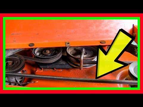
The control panel is strategically positioned for easy access. It houses various controls such as throttle, ignition switch, and other essential features. Familiarity with this interface enhances user experience and ensures safe handling of the machinery.
Wheel and Axle Arrangement
The arrangement of wheels and axles plays a crucial role in the overall functionality and stability of machinery. This setup not only supports the structure but also facilitates smooth movement across various terrains. A well-designed configuration ensures optimal performance, contributing to the efficiency and reliability of the equipment.
Components of the System
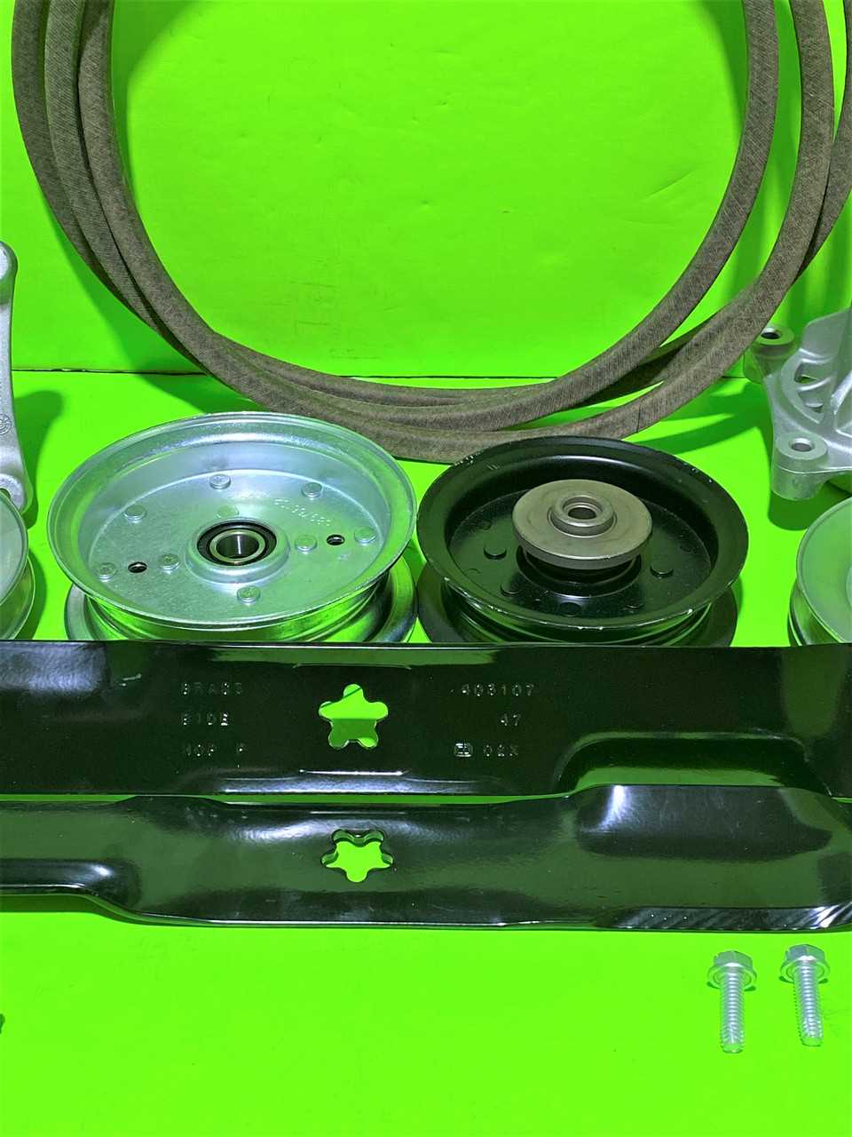
The main components involved in this assembly include the wheels, axles, bearings, and any additional supports. Each element must be meticulously crafted to withstand operational stresses while providing ease of mobility. The selection of materials and design features significantly influences the durability and effectiveness of the arrangement.
Importance of Maintenance
Regular maintenance of the wheel and axle setup is essential for preventing wear and tear. Inspecting for signs of damage or misalignment can help maintain the integrity of the system. Proper lubrication and timely replacements of worn parts contribute to extending the lifespan of the machinery, ensuring continued performance and safety.
Safety Features Overview
This section provides a comprehensive look at the essential safety mechanisms incorporated into modern lawn maintenance equipment. These features are designed to enhance user protection and ensure safe operation, reducing the risk of accidents during use.
Among the critical safety elements are emergency shut-off systems, which immediately halt the machine’s operation in case of an emergency. Additionally, there are protective guards that cover moving parts, minimizing the chance of injuries caused by contact with blades or other components.
| Feature |
Description |
| Emergency Stop |
A mechanism that allows the operator to quickly shut down the equipment in urgent situations. |
| Operator Presence Control |
This system ensures that the machine will not operate unless the user is in a designated position, preventing unintended activation. |
| Blade Guards |
These covers protect users from direct contact with sharp blades during operation. |
| Parking Brake |
Helps keep the equipment stationary when not in use, preventing accidental movement. |
Understanding these features is vital for maintaining a safe environment while performing outdoor tasks. Proper knowledge and adherence to safety protocols can significantly reduce the likelihood of mishaps and promote a safer experience for all users.
Muffler and Exhaust System Design
The design of a muffler and exhaust system plays a crucial role in managing engine emissions and noise levels. Effective engineering in this area ensures optimal performance while adhering to environmental standards. The layout typically includes various components that work in unison to facilitate the safe expulsion of exhaust gases, minimizing back pressure and enhancing engine efficiency.
Key Components of the System
The primary elements of the exhaust setup include the manifold, catalytic converter, muffler, and tailpipe. Each part serves a distinct purpose, from channeling exhaust gases away from the engine to reducing noise and converting harmful emissions into less harmful substances. A well-designed system is essential for maintaining engine health and compliance with regulatory requirements.
Importance of Material Selection
Choosing the right materials is vital for durability and performance. Commonly used materials include stainless steel and aluminized steel, which provide resistance to corrosion and heat. This selection impacts the longevity of the components and the overall effectiveness of the exhaust system, ensuring it withstands the rigors of operation while delivering the desired acoustic characteristics.
Maintenance Parts Locations
Understanding the placement of essential components is crucial for effective upkeep of your equipment. Proper knowledge of where to find these elements enables easier access during maintenance tasks, ensuring optimal performance and longevity of the machine.
Engine Components: The primary machinery elements, including filters and belts, are typically located near the engine housing. Regular checks and timely replacements can prevent performance issues and extend the life of the engine.
Chassis Assembly: Key elements such as wheels and axles are usually positioned around the chassis. It is important to inspect these areas frequently for wear and tear, as they contribute significantly to the overall functionality and stability of the device.
Control Mechanisms: Accessing levers and switches can usually be done from the operator’s position. Regular cleaning and adjustment of these controls enhance user experience and ensure safety during operation.
|
