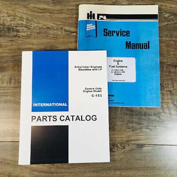
When it comes to maintaining or repairing a vehicle, having a clear overview of how each element is organized is essential. A structured visualization allows mechanics and enthusiasts to identify and understand the intricate relationships between different mechanical elements. This type of guide offers valuable insight, making the task of pinpointing and addressing specific issues much more manageable.
Visual aids serve as a helpful tool in guiding users through complex configurations, providing clarity where verbal explanations might fall short. Whether you’re addressing routine upkeep or tackling a more involved restoration project, knowing the placement and function of each element can be a crucial advantage.
In addition to easing the repair process, these visual layouts also play a role in helping users source the correct components for replacement or upgrades. With a clear, organized view, it’s easier to find what you need and ensure proper fitment, ensuring that the work proceeds smoothly and efficiently.
Overview of International 504 Components
Exploring the main elements of this machine reveals a well-organized structure, designed for efficient operation and durability. Understanding how these elements work together provides valuable insight into its overall functionality. Each section contributes to the unit’s performance, ensuring reliability in various applications.
Key Mechanical Features
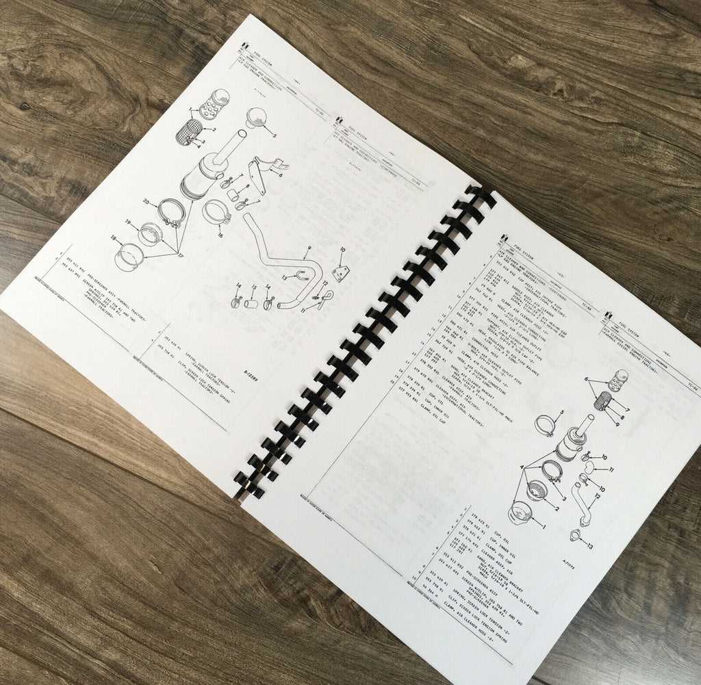
The mechanical assembly of this model consists of several critical components that enhance its power and precision. These elements work in harmony to deliver optimal performance, even in demanding environments. The focus on robust construction ensures long-lasting use with minimal maintenance.
Essential Electrical Systems
The electrical setup is designed to support smooth operations and ensure that all systems function efficiently. It integrates a combination of circuits and controls, which are essential for the model’s overall reliability and ease of use. Proper maintenance of these systems is key to extending the machine’s service life.
Exploring the Engine Assembly Structure
The engine assembly consists of multiple interconnected components, each playing a critical role in ensuring the smooth operation of the machinery. Understanding how these elements fit together helps in maintaining and troubleshooting mechanical systems effectively.
Key Components Overview
- Cylinder Block: This is the core part that houses various moving parts and provides structural support.
- Pistons: Positioned within the cylinders, they convert fuel combustion into mechanical power.
- Crankshaft: The crankshaft translates the pistons’ linear motion into rotational energy.
- Valves: These regulate the flow of air and fuel into the cylinders and allow exhaust gases to exit.
How the Components Work Together
The seamless coordination between these parts is vital for optimal engine function. Pistons move in synchronization with the crankshaft, while the valves open and close at precise intervals. The combustion process drives these motions, ensuring consistent power delivery and efficiency.
- Fuel enters the chamber, mixed with air for ignition.
- The pistons move up and down, compressing the fuel-air mixture.
- After combustion, the exhaust is released, and the cycle repeats.
Each part within the engine has a specific task, and when all work in
Hydraulic System Layout and Key Parts
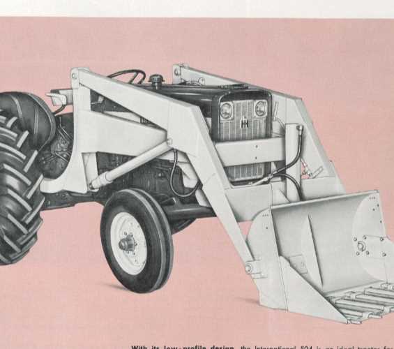
The hydraulic mechanism is crucial for ensuring smooth and efficient operation of various components in machinery. By transferring fluid under pressure, this system powers different functions, from lifting to moving attachments. Understanding the structure and the key components involved is essential for maintaining and troubleshooting the system effectively.
Main Components
A typical hydraulic setup consists of several vital elements, each playing a specific role in enabling fluid flow and pressure control.
- Pump: Converts mechanical power into hydraulic energy by moving fluid through the system.
- Control Valves: Direct the flow of hydraulic fluid to different parts of the machine, allowing for precise control of various movements.
- Cylinders: Actuators that transform hydraulic pressure into mechanical motion, often responsible for lifting or moving functions.
- Reservoir: Stores the hydraulic fluid, ensuring the system has a sufficient supply and maintaining pressure balance.
Fluid Flow and Pressure Control
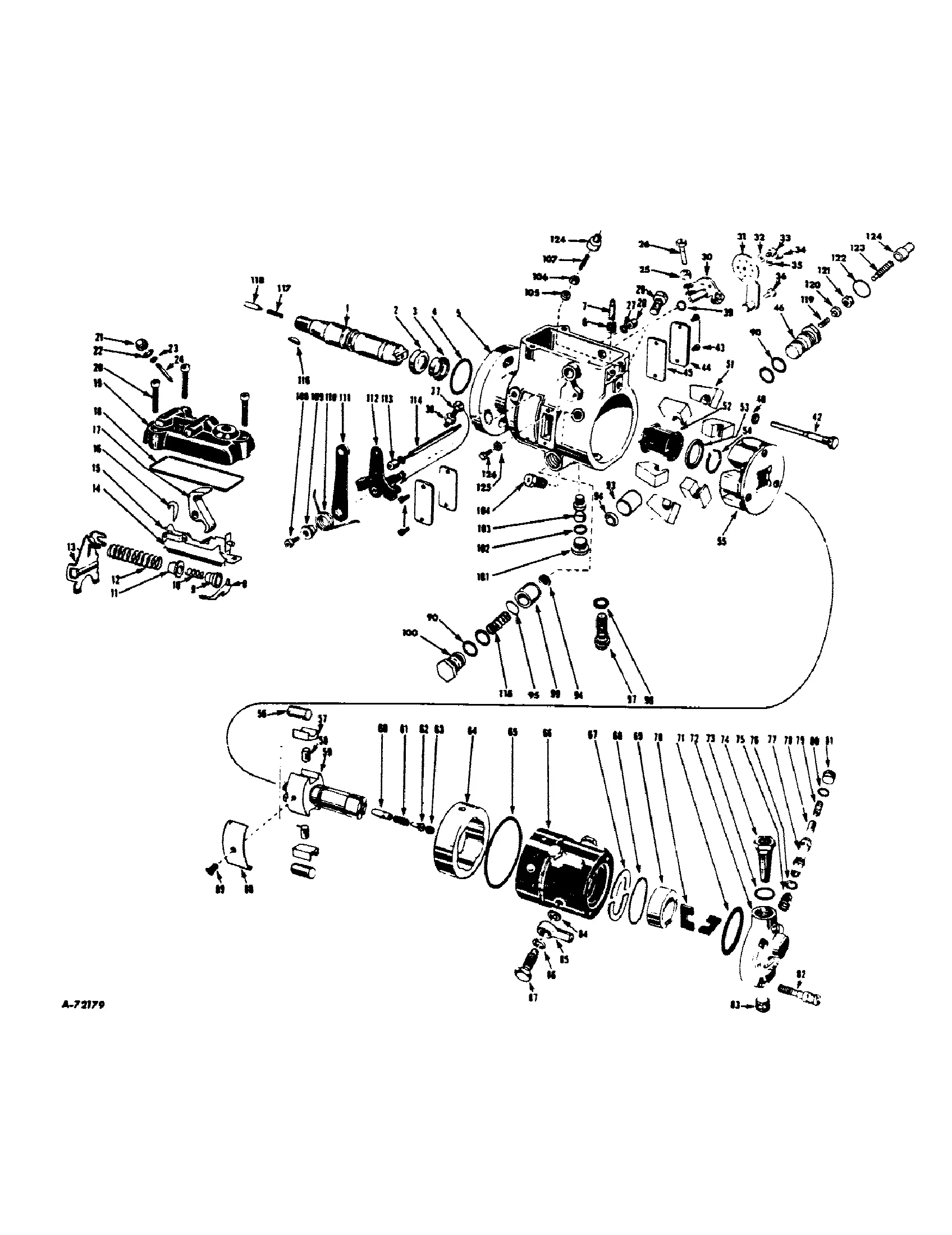
Hydraulic systems rely on carefully regulated fluid movement to function efficiently. Control mechanisms like pressure regulators and flow restrictors ensure that each component
Understanding the Electrical Wiring Diagram
To grasp the fundamentals of electrical connections in complex systems, it’s essential to examine how individual circuits function and interact. These illustrations provide a visual representation of how various components are linked together, ensuring smooth operation of the entire system. Recognizing the relationships between power sources, connectors, and pathways can help in troubleshooting or making necessary adjustments.
Below is a simplified table to help identify typical elements found in such diagrams:
| Component | Description | Function | |||||||||||||||||||||||||||
|---|---|---|---|---|---|---|---|---|---|---|---|---|---|---|---|---|---|---|---|---|---|---|---|---|---|---|---|---|---|
| Battery | Provides the main power supply | Supplies energy to the system | |||||||||||||||||||||||||||
| Fuse | Protects circuits from overload | Prevents electrical damage | |||||||||||||||||||||||||||
| Switch | Controls the flow of electricity | Enables or disables circuits | |||||||||||||||||||||||||||
| Ground | Provides a return path for current |
| Component | Function | ||||||||||||||||||||||
|---|---|---|---|---|---|---|---|---|---|---|---|---|---|---|---|---|---|---|---|---|---|---|---|
| Steering Wheel | Allows the driver to control direction. | ||||||||||||||||||||||
| Component | Description |
|---|---|
| Clutch Disc | Connects the engine’s flywheel to the transmission input shaft, allowing engagement and disengagement of power transfer. |
| Pressure Plate | Exerts pressure on the clutch disc, ensuring it makes contact with the flywheel to transmit torque effectively. |
| Flywheel | Acts as a mounting surface for the clutch disc, providing the necessary inertia to smooth out engine vibrations during operation. |
| Throw-Out Bearing | Engages and disengages the pressure plate when the clutch pedal is pressed, allowing for shifting between gears. |
| Clutch Fork | Transmits the force from the clutch pedal to the throw-out bearing, facilitating smooth operation of the clutch assembly. |
Exhaust System Layout and Key Elements
The configuration of the exhaust mechanism plays a crucial role in optimizing engine performance and reducing emissions. A well-designed system ensures that gases produced during combustion are efficiently expelled, contributing to overall functionality and longevity of the vehicle. Understanding the components involved is essential for effective maintenance and upgrades.
Key components of the exhaust setup typically include the manifold, which collects exhaust gases from the engine, and the catalytic converter, designed to reduce harmful emissions. The muffler serves to minimize noise, while the exhaust pipe directs gases away from the engine and vehicle body.
Proper alignment and connection of these elements are vital to maintain system integrity and prevent leaks. Regular inspection and maintenance of the exhaust system not only enhance performance but also ensure compliance with environmental regulations.
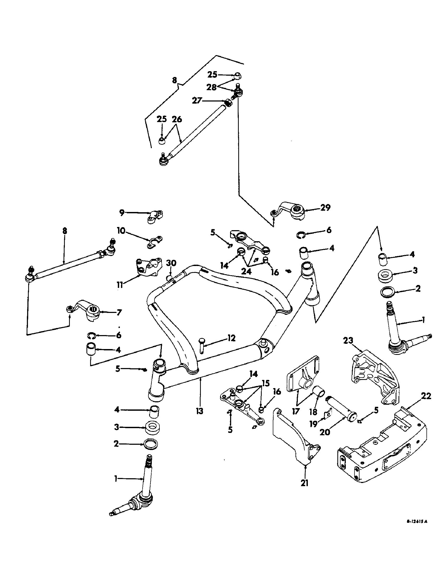
Axle Assembly and Structural Diagram
This section provides a comprehensive overview of the axle assembly and its structural components. Understanding the arrangement and function of each part is essential for maintenance and troubleshooting. This overview highlights the key elements that contribute to the overall stability and performance of the vehicle.
The axle assembly plays a crucial role in the vehicle’s framework, supporting the weight and facilitating movement. It consists of various interconnected parts that work together to ensure effective operation and durability. Below is a structured representation of the components involved:
| Component | Description |
|---|---|
| Axle Shaft | Transfers torque from the transmission to the wheels. |
| Wheel Hub | Connects the wheel to the axle, allowing for rotation. |
| Brake Assembly | Includes components that provide stopping power through friction. |
| Suspension Linkage | Connects the axle to the vehicle frame, allowing for smooth movement. |
| Differential | Distributes power to the wheels, enabling them to rotate at different speeds. |
Each component’s function is vital for the effective operation of the axle assembly, impacting both performance and safety.
Exploring the PTO System Components
The power take-off (PTO) mechanism is a crucial element in agricultural machinery, facilitating the transfer of power from the engine to various implements. Understanding its components can enhance operational efficiency and maintenance practices.
This section delves into the key elements of the PTO system, detailing their functions and significance:
- PTO Shaft: A vital component that connects the tractor to the attachment, transmitting power effectively.
- Clutch Assembly: This mechanism engages and disengages the PTO shaft, allowing for smooth operation when connecting or disconnecting equipment.
- PTO Housing: The protective casing that houses the PTO mechanism, ensuring durability and safety during operation.
- Bearings: Essential for reducing friction and wear, these components support the rotating elements of the system.
- Gearbox: Transforms the rotational speed and torque to suit the specific requirements of different implements.
- Universal Joints: These joints allow for flexibility in the drive line, accommodating changes in angle during operation.
Proper maintenance and understanding of these components can significantly impact the performance and longevity of the machinery.
