In any mechanical system, recognizing how different elements interact and function together is crucial. When dealing with equipment that relies on precision and reliability, having a clear view of how individual units connect can greatly aid in both troubleshooting and maintenance. This section explores the intricate arrangement of essential mechanical elements, providing insight into their roles and relationships.
By visualizing the structural layout of these components, one can better understand the flow of operation within the machinery. Whether you’re maintaining, repairing, or simply familiarizing yourself with the system, understanding how each part fits and functions is an important step toward effective upkeep. Dive into the detailed layout, and you’ll uncover a system designed for both efficiency and durability.
Kawasaki FC420V Engine Breakdown

This section provides a detailed exploration of the internal mechanisms and key components of a commonly used small engine model. Understanding how its essential parts work together can help ensure proper maintenance and troubleshooting. Below is a breakdown of the engine’s crucial areas, each responsible for specific functions that contribute to its overall performance.
Main Components

- Cylinder Block: The main structure housing the piston and valves, essential for combustion and power generation.
- Piston and Crankshaft: The piston moves within the cylinder, powered by combustion, while the crankshaft converts this motion into rotational force.
- Carburetor: Regulates the air-fuel mixture, ensuring optimal combustion efficiency.
- Ignition System: Includes spark plug and coil, responsible for igniting the fuel mixture at the right time.
Key Functions
- Cooling System: Keeps the engine temperature regulated through air circulation or a liquid coolant.
- Lubrication: Ensures moving parts operate smoothly and reduces wear over time.
Understanding the Main Engine Components The internal structure of any combustion engine relies on the harmonious interaction of various key elements. These components work together to ensure smooth operation, consistent power delivery, and long-term durability. In this section, we will explore the essential parts that form the foundation of an engine’s performance.
Cylinder and Piston Assembly
The cylinder serves as the central chamber where fuel combustion occurs, driving the movement of the piston. The piston moves up and down within the cylinder, converting the pressure generated by the combustion process into mechanical energy. This energy is then transmitted to the crankshaft, which powers the machine.
Crankshaft and Connecting Rod
The crankshaft is responsible for converting the linear motion of the piston into rotational energy. Connected to the piston by the connecting rod, it plays a critical role in maintaining the engine’s efficiency. As the piston moves, the crankshaft rotates, driving the various mechanical systems that rely on engine power.
Fuel System Structure and Key Parts
The fuel delivery system is designed to ensure the efficient transport of fuel from the reservoir to the engine’s combustion chamber. Its architecture integrates various essential components that work together to manage fuel flow, optimize combustion, and maintain the overall functionality of the engine. Understanding the layout and individual components is crucial for proper maintenance and troubleshooting of this system.
Component Description Fuel Pump Ensures the steady movement of fuel from the tank to the engine by creating the necessary pressure for fuel flow. Fuel Filter Removes impurities and debris from the fuel to prevent clogging and maintain smooth operation. Carburetor Mixes the air and fuel in precise ratios before delivering it to the combustion chamber. Fuel Line Serves as the conduit that transfers fuel between the tank, pump, and carburetor. Fuel Tank Ignition Mechanism Overview and Its Function
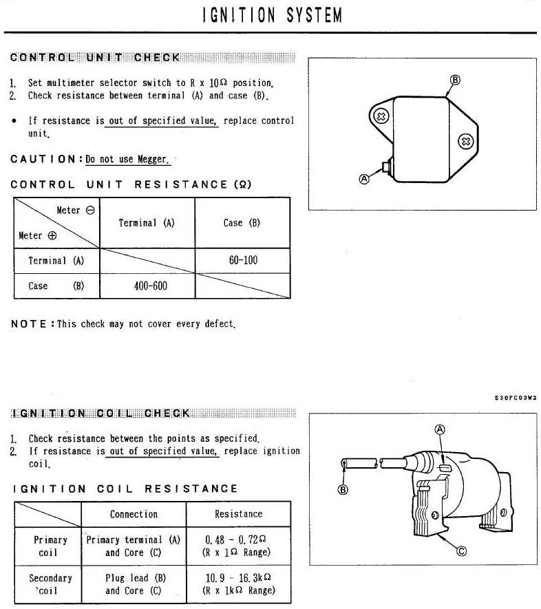
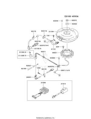
The ignition system is a critical component that ensures the engine starts and operates smoothly. It plays a key role in delivering the necessary spark to ignite the fuel-air mixture, enabling the combustion process. This mechanism is designed to provide consistent performance, optimizing the efficiency and reliability of the power unit.
Main Components of the Ignition System
- Flywheel – A rotating component that generates electrical energy as it spins, helping to produce the spark.
- Ignition Coil – Converts the low voltage from the battery into the high voltage needed to ignite the fuel.
- Spark Plug – Delivers the electrical charge to the combustion chamber, creating the spark that ignites the air-fuel mixture.
How the Ignition System Works
- The flywheel rotates, producing a magnetic field.
- This energy is sent to the ignition coil, where it is transformed into high voltage.
- The spark plug receives the electrical charge, creating a spark inside the combustion chamber.
- The fuel-air mixture ignites, starting the engine’s power cycle.
- Cylinder Head: This essential component seals the combustion chamber, ensuring proper pressure and temperature regulation. It also houses several integral parts.
- Valves: Responsible for controlling the flow of air and fuel, these are positioned precisely to manage intake and exhaust with the right timing.
- Valve Springs: These keep the valves in place, allowing for smooth operation by returning them to their closed positions after each cycle.
- Rocker Arms: These mechanical levers transfer motion from the camshaft to the valves, ensuring they open and
Exploring the Cooling System Design
In any high-performance engine, the cooling system plays a critical role in ensuring efficient operation and longevity. By effectively managing heat generated during operation, this system maintains optimal temperatures and prevents overheating, which could lead to serious mechanical issues. Understanding the structure and components of this system is essential for keeping the machine running smoothly under various conditions.
Main Components of the Cooling Mechanism
The cooling setup relies on several key elements working together. Each of these parts plays a specific role in regulating the temperature and dissipating excess heat.
- Airflow guides: These channels direct cool air through the system, ensuring that all parts receive adequate ventilation.
- Fan blades: Positioned strategically, the blades enhance airflow, circula
Drive Belt and Pulley Configuration
Understanding the alignment and interaction between the main belt and pulleys is essential for ensuring optimal transmission of power in the system. The configuration plays a key role in the overall efficiency and performance, allowing smooth operation and minimal wear over time.
The arrangement typically involves multiple rotating elements that guide the belt along its path. Each component must be precisely positioned to maintain tension and reduce the risk of slippage. The correct balance between the belt and pulley dimensions ensures consistent operation under varying loads.
Component Function Material Main Drive Belt Transfers rotational motion Reinforced Rubber Primary Pulley Provides initial movement Metal Alloy Secondary Pulley Guides and supports belt motion Steel Tensioner Maintains belt tension Aluminum Electrical Wiring Diagram and Connections

This section provides an overview of the electrical schematics and the interconnections required for optimal performance of the engine. Understanding the layout and functionality of the electrical system is crucial for troubleshooting and ensuring safe operation.
The electrical system comprises various components that work in unison. The following elements are typically included in the wiring layout:
- Battery: Supplies the necessary power for starting the engine and operating electrical accessories.
- Ignition System: Responsible for igniting the fuel-air mixture, ensuring proper combustion.
- Alternator: Generates electricity to recharge the battery and power the electrical systems while the engine is running.
- Wiring Harness: Connects all electrical components, providing pathways for current flow.
- Switches: Control the operation of various electrical functions, such as starting and lighting.
When working with the electrical system, consider the following steps:
- Inspect all connections for corrosion or damage.
- Ensure proper grounding for all components to prevent electrical failures.
- Follow the wiring schematic closely when making any modifications or repairs.
- Test each component individually to confirm functionality before reassembly.
By familiarizing yourself with the wiring configuration and taking proper precautions, you can maintain the reliability and safety of the engine’s electrical system.
Exhaust System Parts and Their Role
The exhaust assembly of an engine plays a crucial role in managing emissions and enhancing performance. It is designed to channel exhaust gases away from the engine, ensuring optimal operation and compliance with environmental standards. Understanding the components involved in this system is essential for maintaining efficiency and longevity.
Key components of the exhaust assembly include:
- Muffler: This component reduces noise produced by the engine during operation. It also helps in controlling back pressure, which can affect engine performance.
- Exhaust Manifold: The manifold collects exhaust gases from multiple cylinders and directs them into the exhaust system. Its design significantly impacts how efficiently gases are expelled from the engine.
- Exhaust Pipe: This pipe transports the exhaust gases from the manifold to the muffler and ultimately out of the vehicle. The diameter and material of the pipe can influence the flow of gases.
- Catalytic Converter: This crucial element reduces harmful emissions by converting toxic gases into less harmful substances before they are expelled into the atmosphere.
- Resonator: Often used in conjunction with the muffler, this part helps to fine-tune the sound of the exhaust and reduce certain frequencies that may be undesirable.
Each of these components plays a vital role in ensuring the proper functioning of the exhaust system. Regular inspection and maintenance of these elements can lead to improved engine performance and lower emissions, contributing to a more efficient and environmentally friendly operation.
Air Filter and Intake Flow Design
The efficiency of an engine significantly relies on the design of its air filtration system and the management of airflow into the combustion chamber. A well-optimized intake design ensures that clean air reaches the engine while minimizing restrictions that could impede performance. This section delves into the essential aspects of air filtration and intake flow design.
Effective air filtration is crucial for maintaining engine performance and longevity. The components involved serve to prevent dirt and contaminants from entering the combustion process. Key considerations in air filter design include:
- Filter Material: The choice of material affects filtration efficiency and airflow capacity.
- Surface Area: A larger surface area enhances airflow and reduces resistance.
- Maintenance: Easy access for cleaning or replacement is essential for optimal performance.
In addition to filtration, the intake flow system must be carefully engineered to facilitate optimal airflow. This involves:
- Intake Shape: The geometry of the intake affects how air enters the engine, influencing performance characteristics.
- Path Length: Shorter intake paths can enhance responsiveness and reduce lag.
- Velocity Stacks: These components can help increase airflow velocity, improving overall efficiency.
Ultimately, a harmonious balance between filtration and intake design is critical for maximizing engine performance. Regular assessment and optimization of these components can lead to significant improvements in power output and efficiency.
Carburetor Assembly: Key Elements Explained
The carburetor plays a crucial role in controlling the air and fuel mixture that powers the engine. Understanding the essential components of this mechanism can help in diagnosing issues or performing maintenance efficiently. Each part works together to ensure the smooth functioning of the engine by regulating fuel delivery based on various operating conditions.
Component Function Float Regulates fuel levels by opening or closing the fuel inlet needle based on the fuel chamber’s capacity. Needle Valve Controls the flow of fuel into the float chamber, ensuring proper fuel levels for combustion. Main Jet Manages the amount of fuel entering the carburetor’s mixing chamber, influencing fuel-to-air ratios at higher speeds. Idle Jet Delivers fuel to the engine during idle operation, ensuring smooth and stable performance when the throttle is closed. Throttle Valve Regulates the airflow into the carburetor, controlling the engine’s speed and output power. Cylinder Head and Valve Layout
The structure of the upper section of the engine plays a crucial role in managing airflow, combustion, and overall engine performance. Understanding how the various components are arranged helps ensure efficient maintenance and troubleshooting. The head houses key elements that control both the intake and exhaust processes, influencing the engine’s power and longevity.