Power
Key Parts of the Mule 550 Engine
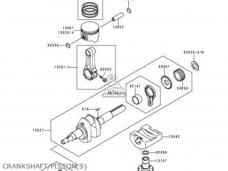
The engine powering this utility vehicle is built from a variety of essential components that work together to ensure optimal performance and durability. Each part plays a crucial role in the overall function, contributing to the smooth operation of the machine. In this section, we will focus on the main elements of this engine, emphasizing their importance and the roles they play in maintaining efficiency and reliability.
Core Mechanical Components
The engine block serves as the foundation, housing the pistons, crankshaft, and other critical parts. The pistons move within the cylinders, converting fuel into mechanical energy, while the crankshaft turns this energy into motion
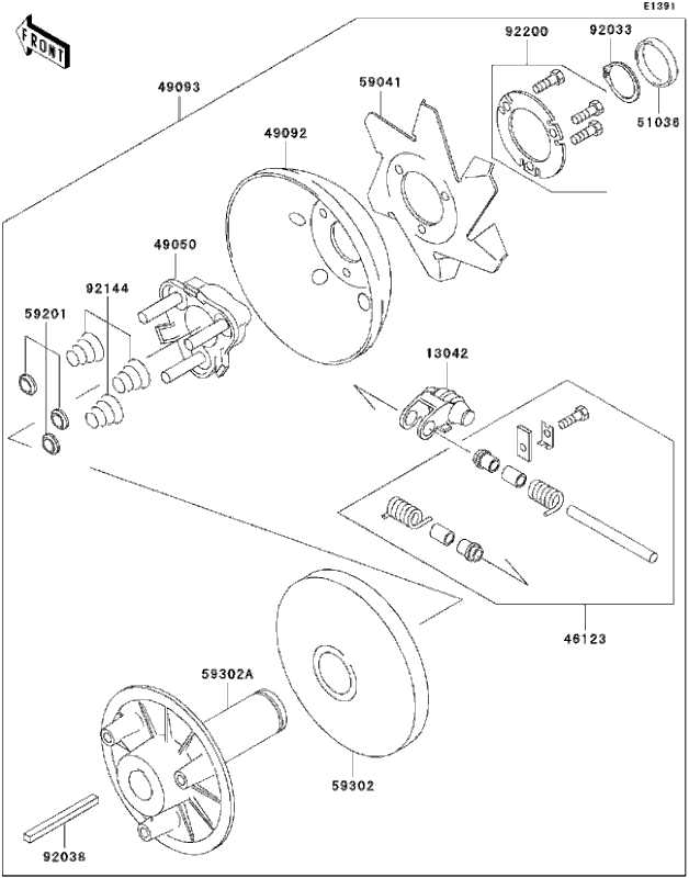
Understanding the Transmission System Layout
The transmission system is a critical component in any utility vehicle, ensuring the seamless transfer of power from the engine to the wheels. This system is responsible for managing the speed, direction, and overall control of the vehicle, making it essential for smooth operation. In this section, we will explore the basic structure and arrangement of the transmission system, shedding light on its key elements and how they work together to ensure efficient performance.
Key Components of
Examining the Electrical System and Wiring
The electrical system plays a crucial role in the overall functionality of any utility vehicle, providing power to essential components and ensuring smooth operation. This section covers the evaluation of the system’s structure and connections, helping to identify key elements that contribute to efficient performance. Proper maintenance and inspection of these elements can prevent future issues.
Key Components
- Battery and its connections
- Ignition system
- Lighting circuits
- Switches and fuses
Wiring Inspection
- Begin by checking for
Chassis Structure and Frame Components
The framework and support structure are fundamental to ensuring stability and durability in utility vehicles. This section explores the key components that form the backbone, providing the necessary strength to handle various terrains and loads. Each element contributes to maintaining the overall integrity of the vehicle while supporting its operational needs.
Main Frame Assembly
The central frame is designed to distribute weight evenly and withstand external forces during operation. It serves as the foundation, connecting various subsystems and ensuring they function cohesively. Below are the critical components within this structure:
- Crossmembers:
Suspension and Steering Mechanisms
The suspension and steering systems are crucial components in any utility vehicle, contributing significantly to its overall performance and user experience. These systems work in harmony to ensure that the vehicle remains stable and responsive, even on uneven terrains. A well-designed suspension system absorbs shocks from the ground, providing comfort to the occupants while maintaining traction and control.
The steering mechanism allows the driver to maneuver the vehicle with precision, making it easier to navigate through tight spaces or rugged paths. Various elements, such as linkages and joints, come together to form a reliable and efficient system that translates the driver’s inputs into smooth directional changes. Understanding these mechanisms enhances the ability to maintain and repair them, ultimately leading to a more enjoyable driving experience.
Moreover, the interaction between the suspension and steering systems affects the vehicle’s handling and stability. Proper adjustments and maintenance are essential to ensure that both systems function optimally, enhancing safety and performance during operation.
Fuel System Parts and Connections
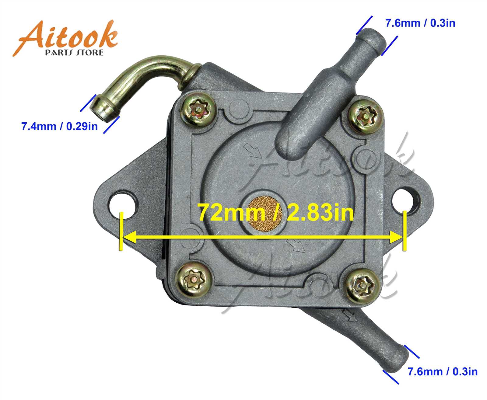
The fuel system is a critical component of any vehicle, responsible for delivering the necessary energy to the engine for optimal performance. Understanding the various elements and their interconnections is essential for effective maintenance and troubleshooting. This section will explore the key components involved in the fuel delivery process and their relationships.
Key Components
- Fuel Tank
- Fuel Pump
- Fuel Filter
- Fuel Lines
- Injector System
Connections Overview
Proper connections between the elements of the fuel delivery system are vital for ensuring efficient operation. Here are the main connections to consider:
- Fuel Tank to Pump: This connection facilitates the transfer of fuel from the storage area to the pump.
- Pump to Filter: After being drawn from the tank, the fuel flows through the filter to remove impurities.
- Filter to Injectors: Clean fuel is then directed to the injectors, where it is atomized and mixed with air for combustion.
Brake System Components Explained
The braking mechanism is a crucial aspect of any vehicle, ensuring safety and control during operation. Understanding the various elements involved in this system can help users maintain and troubleshoot effectively. Each component plays a significant role in the overall functionality, contributing to the vehicle’s ability to stop or slow down as needed.
Key Components of the Brake System

At the heart of the braking system lies the brake pedal, which initiates the stopping process. When pressed, it activates a series of hydraulic mechanisms that ultimately engage the brakes at the wheels. This action is facilitated by the master cylinder, which generates hydraulic pressure, allowing the force from the pedal to be transmitted through fluid to the brake assemblies.
Types of Braking Mechanisms
There are typically two types of braking systems: disc brakes and drum brakes. Disc brakes consist of a flat rotor and caliper that grip the rotor to slow down the vehicle, offering better performance under heavy use. In contrast, drum brakes utilize a cylindrical drum and brake shoes, which expand against the drum’s inner surface. Both systems have unique advantages and applications, making them suitable for different vehicle types and driving conditions.
|


