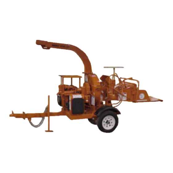
Guide to Blade Assembly Process
In this section, we delve into the step-by-step process of assembling the cutting blades for efficient operation. Proper blade assembly ensures optimal performance and longevity of the cutting equipment.
Preparing for Assembly
- Gather all necessary components required for blade installation.
- Inspect each blade and related parts for any signs of wear or damage.
- Clean the assembly area to prevent debris from interfering with the assembly process.
Step-by-Step Assembly
- Start by aligning the blades with their designated slots or mounts.
- Secure the blades using appropriate fasteners, ensuring a tight fit without over-tightening.
- Verify the alignment and balance of each blade to maintain operational efficiency.
- Test the assembly by running a brief operational check to ensure proper functionality.
Following these steps guarantees a well-assembled blade configuration, promoting safety and effective chipping performance.
Maintenance Tips for Key Parts
Regular upkeep is crucial for ensuring optimal performance and extending the lifespan of various components. Proper maintenance not only enhances functionality but also prevents potential breakdowns, saving time and reducing repair costs. Here are some essential care practices to keep in mind for the most critical elements.
Lubrication and Cleaning
Keep all moving mechanisms well-lubricated to minimize friction and wear. Use the appropriate type of grease or oil, and apply it regularly based on usage frequency. In addition, clean surfaces and remove any buildup of dirt or debris that could obstruct operation, making sure to reach hidden areas where residue tends to accumulate.
Inspect for Wear and Damage
Routinely check for signs of wear, such as cracks, bends, or thinning, especially on high-stress components. Replace any element showing significant deterioration, as continuing to use it could lead to further damage or malfunction. Tighten any loose fasteners and ensure that all connections are secure to maintain stability.
Replacing Worn Chipper Bearings
Bearings play a crucial role in the smooth operation of many machines, and over time, they can wear out due to friction, load, or inadequate maintenance. If left unchecked, worn bearings can lead to more significant mechanical failures. Proper inspection and timely replacement of these components are essential to ensure the equipment continues running efficiently.
Signs of Bearing Wear
Common signs that bearings may need replacement include unusual noises during operation, increased vibration, or difficulty in rotating the machine’s moving parts. It’s important to regularly check these indicators to prevent further damage.
Steps for Replacing Bearings
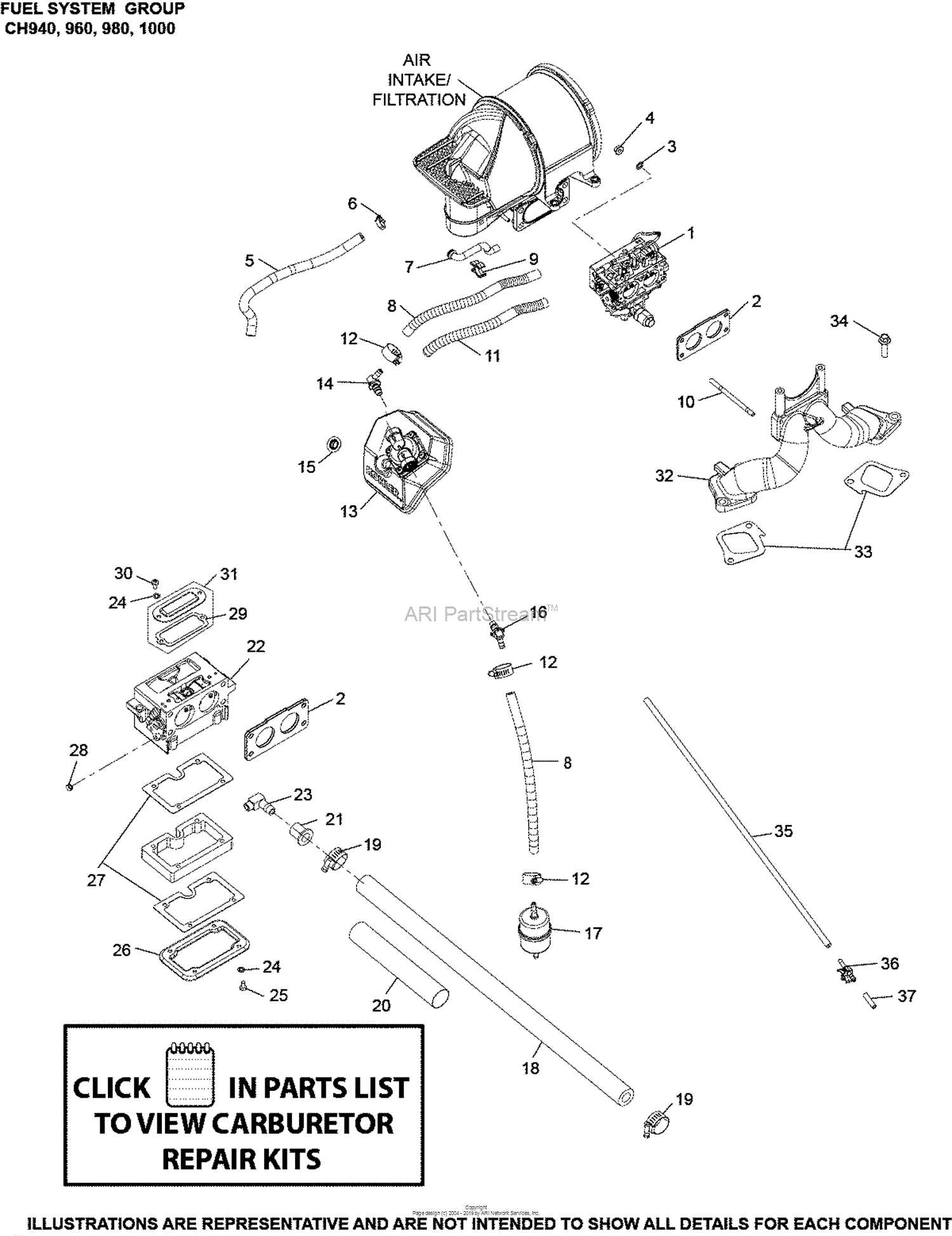
First, ensure the machine is powered off and all safety precautions are taken. Remove the housing that covers the bearing, then carefully extract the worn component. Once the old part is removed, inspect the surrounding area for any signs of damage or debris. Install the new bearing by aligning it correctly and securing it in place
Common Equipment Issues
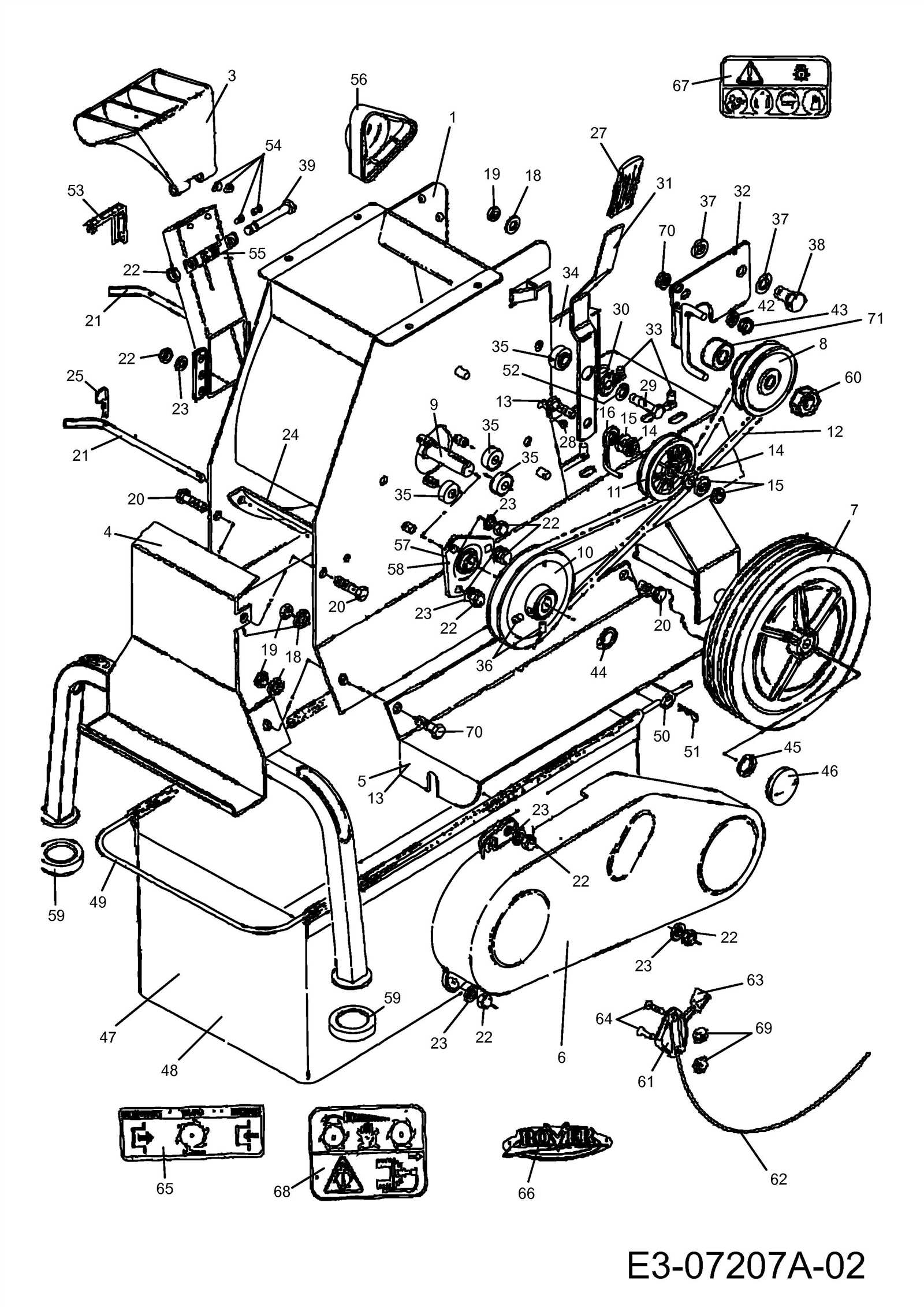
When operating industrial machinery, users may encounter various operational challenges that can affect performance and efficiency. Understanding the most frequent problems can help in timely maintenance and prevent costly repairs.
Overheating
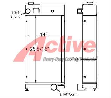
One of the most common issues is the equipment overheating, especially during extended periods of use. This can be caused by insufficient lubrication, clogged air filters, or excessive friction between moving components. Regular inspection and cleaning are essential to avoid such problems.
Reduced Cutting Efficiency

Another frequent issue is a noticeable decrease in cutting performance. This is often due to dull or damaged cutting edges, improper calibration of the cutting mechanism, or accumulation of debris. Sharpening the blades and ensuring proper alignment can significantly improve operational efficiency.
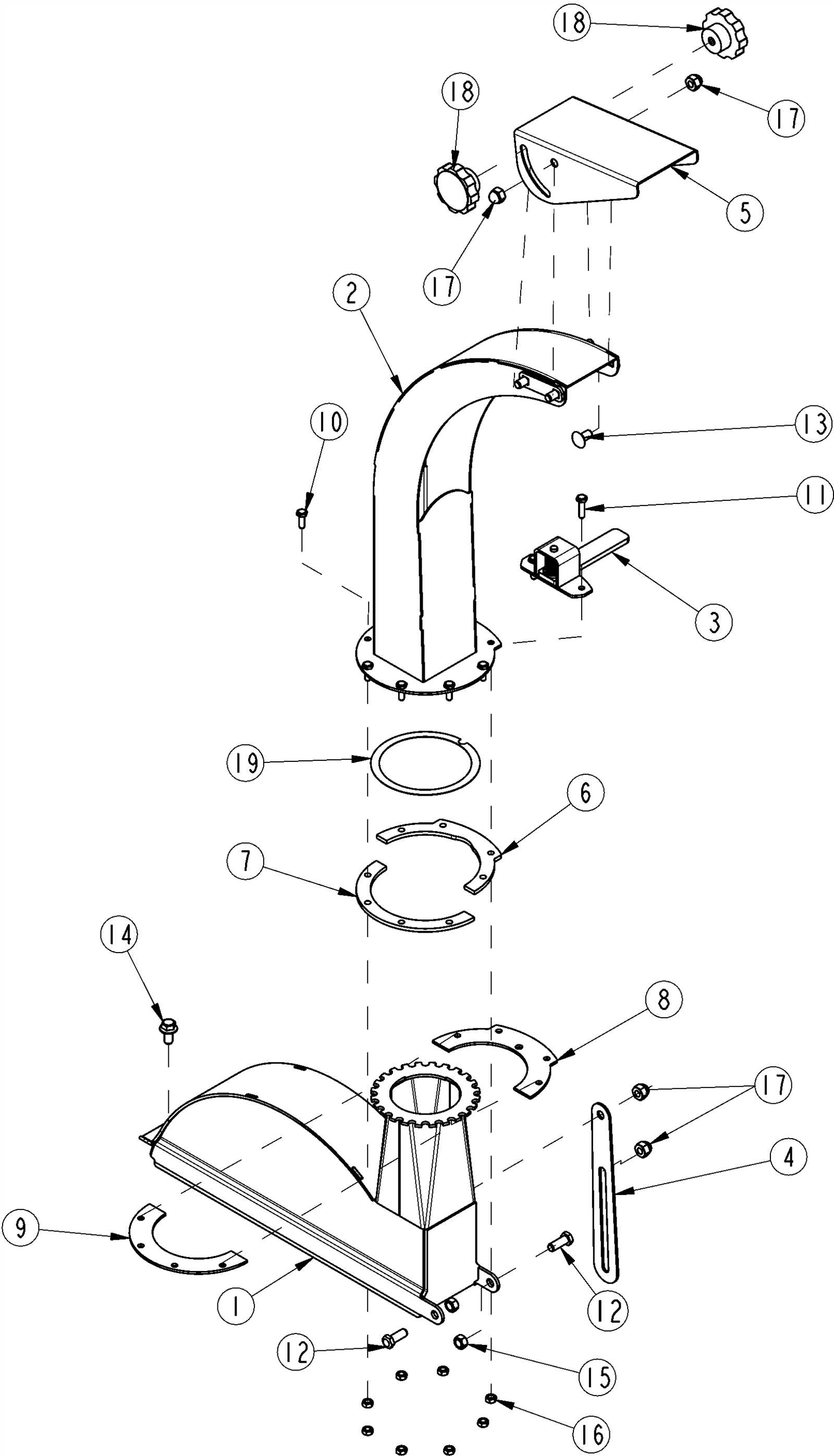
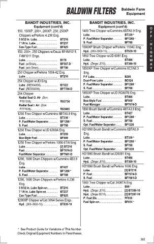
Finding the Correct Spare Parts
When it comes to replacing components in your equipment, it’s essential to ensure that you’re selecting the right elements. Knowing exactly which items are needed can prevent compatibility issues and ensure that the repair or maintenance process goes smoothly.
To identify the appropriate replacements, it’s important to consider several factors such as the model specifications and how each component interacts with others. By closely following this information, you can avoid unnecessary delays and ensure the longevity of your machinery.
Always double-check the product’s compatibility and refer to any available resources that provide detailed guidance on what parts to use in specific situations.
Chipper Engine Diagram Overview
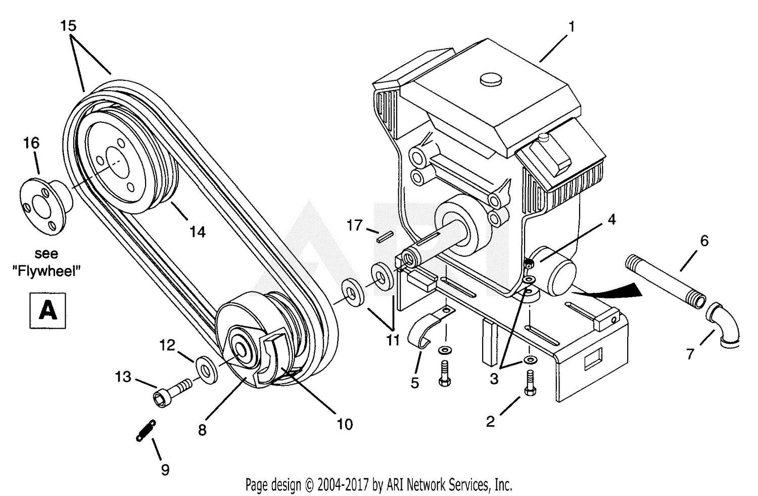
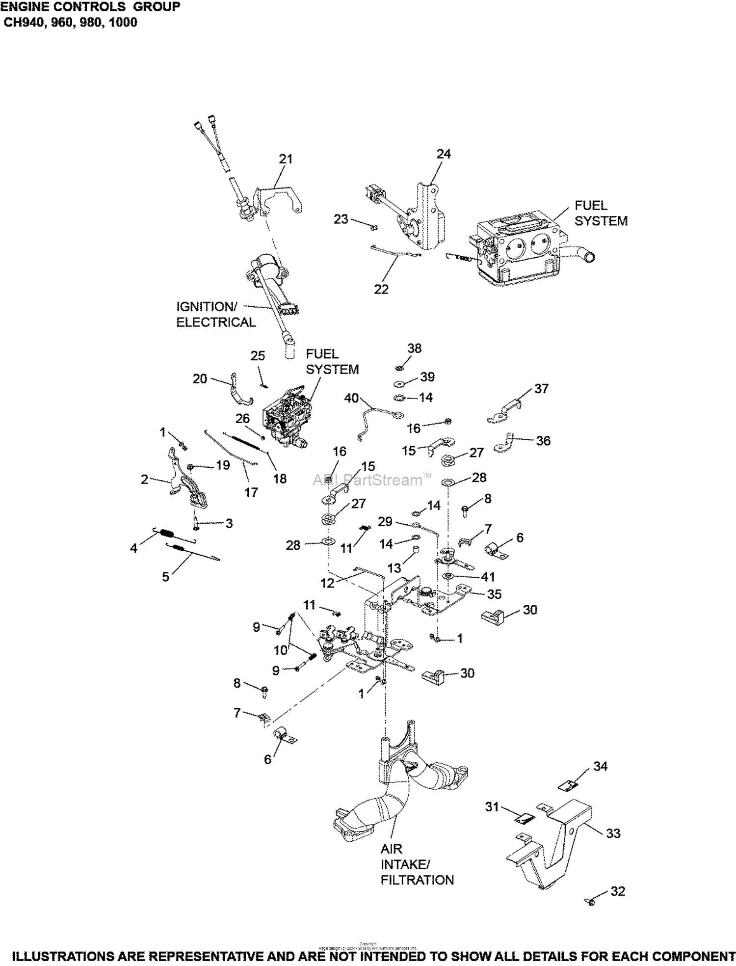
Understanding the layout of a machine’s engine is crucial for efficient maintenance and troubleshooting. This section provides a detailed look at the engine components, helping to identify key areas essential for proper function. Each part of the engine is designed with a specific role, contributing to the overall performance and reliability of the equipment.
Key Components and Their Functions
The engine is comprised of several interconnected elements, including the fuel system, cooling mechanism, and the drive assembly. These systems work together to ensure smooth operation, from power generation to heat regulation, allowing the machine to handle demanding tasks effectively.
Component Connections and Flow
The engine’s internal structure is designed to optimize energy flow. The transmission of power from the engine to the cutting mechanism involves precise timing and coordination between various parts, ensuring that energy is efficiently utilized without excessive strain on any one component.
Hydraulic System Parts Explained
The hydraulic system is essential for the smooth operation of machinery, relying on pressurized fluid to transmit force and control various functions. Understanding the components that make up this system is key to maintaining efficient performance and ensuring reliability over time.
Pumps
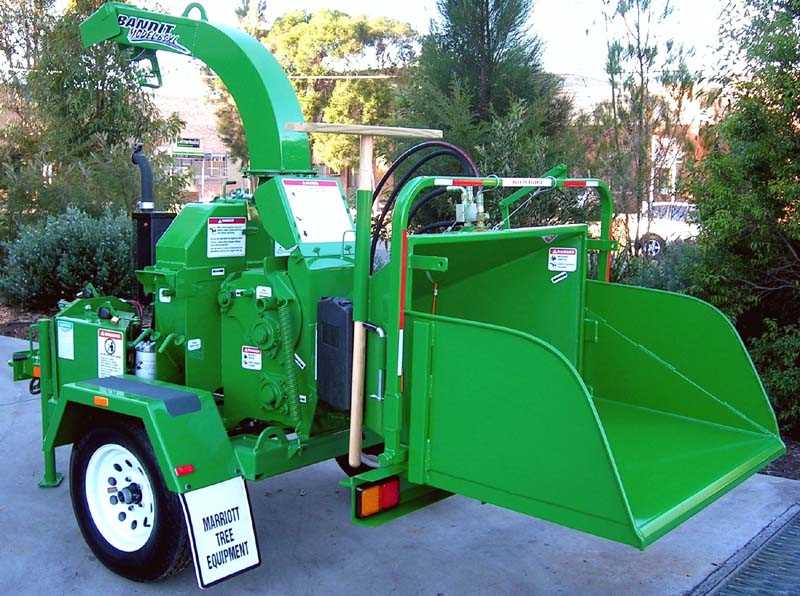
Pumps are the heart of the hydraulic system, responsible for converting mechanical energy into fluid power. They create the necessary flow and pressure to drive the hydraulic fluid through the system, enabling various tasks to be performed efficiently.
Valves and Cylinders
Valves regulate the flow and direction of the fluid, allowing precise control over different operations. Cylinders, on the other hand, convert the fluid’s pressure into linear motion, playing a critical role in lifting, pushing, or pulling mechanical components.
Sharpening and Replacing Blades
Maintaining the cutting efficiency of your equipment depends heavily on keeping the blades sharp and well-maintained. Dull edges can lead to reduced performance and increased strain on the machinery. Regular sharpening and timely replacement of worn blades are essential for optimal operation and safety.
How to Sharpen the Blades
Begin by carefully removing the blades from the unit. Once removed, clean them thoroughly to eliminate any debris or buildup. Sharpen the edges using a grinding tool or file, ensuring an even finish across the entire cutting surface. After sharpening, balance the blade by checking for any uneven weight distribution, as this can cause unnecessary wear.
When to Replace the Blades

If the blades show signs of deep wear, cracks, or are difficult to sharpen, it’s time to replace them. Continuing to use heavily worn blades may result in poor performance and can lead to mechanical issues
Identifying Electrical System Components
Understanding the layout and functionality of the electrical system is essential for maintaining the performance and safety of machinery. Each element of the system plays a critical role in ensuring proper energy flow and operational efficiency.
Wiring Harness: This network of cables is responsible for transmitting electrical signals between various components. Proper connection and insulation are key to preventing malfunctions.
Control Module: The control module serves as the brain of the system, managing the interaction between different electrical elements. It regulates processes such as power distribution and signal coordination.
Relays and Fuses: These safety devices protect the system from overloads by breaking the circuit when necessary. Fuses must be inspected regularly to ensure the system remains secure.
Power Source: Whether it’s a battery or an alternator, the power source is the foundation of the entire electrical system, supplying the necessary energy to keep the machine running.
Safety Mechanisms and Their Function
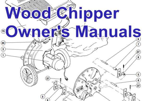
Ensuring operator safety is a key aspect of equipment design, with various mechanisms in place to prevent accidents and ensure smooth operation. These features help protect users from harm and enhance the overall reliability of the machine.
The safety systems are carefully engineered to respond to specific scenarios, minimizing risks associated with misuse or malfunction.
- Emergency Stop Button: This feature allows for an immediate shutdown of the equipment in case of unexpected situations, reducing potential hazards.
- Safety Guards: Physical barriers are designed to prevent access to dangerous moving parts, ensuring that operators remain at a safe distance from the machinery during use.
- Automatic Shutdown: Sensors are used to detect issues such as overloads or blockages, automatically halting operation to prevent damage and injury.
- Warning Systems: Audible and visual alerts notify the operator
Troubleshooting Chipper Part Failures
Mechanical equipment can experience various malfunctions over time due to wear and tear or improper use. Identifying the root cause of these issues is crucial to ensure optimal performance and prevent further damage. This section focuses on common breakdowns and how to address them effectively, helping maintain functionality and prolong the machine’s life.
Common Signs of Wear
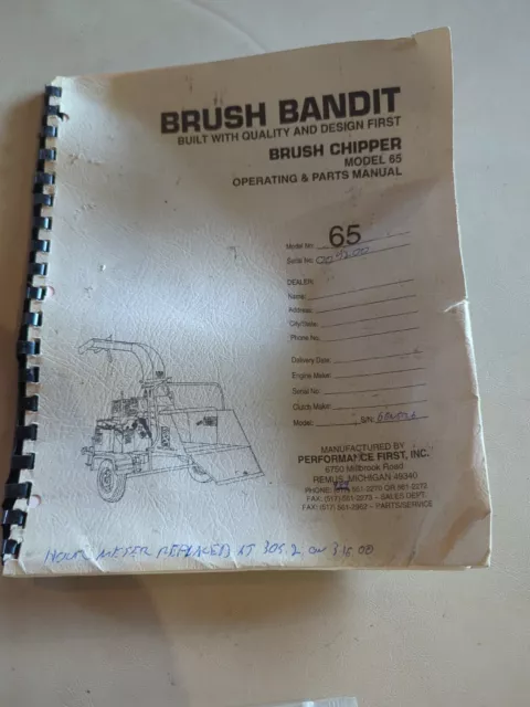
Symptoms of component failure can often be subtle but gradually worsen. Look for unusual noises, reduced efficiency, or visible damage on the equipment’s moving elements. Regular checks and timely replacements can prevent larger problems from developing.
Effective Repair Strategies
When diagnosing issues, it’s essential to pinpoint the affected mechanism. Thorough cleaning and lubrication are often the first steps in fixing minor performance dips. If the problem persists, further inspection and replacement of the faulty element may be necessary. Always follow manufacturer guidelines to ensure safety
