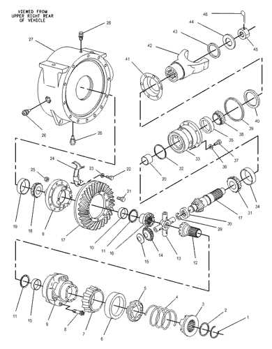
When working with complex machinery, understanding how various elements are organized is crucial for efficient operation and maintenance. Recognizing the structure and connections between mechanical systems allows for quicker diagnostics and repairs, reducing downtime and enhancing performance.
Each element of the machinery plays a vital role in its overall functionality. By gaining insight into how these systems interconnect, technicians and operators can more easily identify issues, replace worn-out components, and ensure the machine continues to run smoothly.
Visual references and clear organization of these components are key to ensuring seamless workflow, whether for regular maintenance or troubleshooting specific malfunctions. A well-detailed breakdown of the machine’s layout provides valuable insights that can save time and resources in both the short and long term.
Cat 416 Backhoe Parts Overview
Understanding the key components of a heavy-duty digging machine is crucial for ensuring optimal performance and maintenance. Each element plays a specific role in supporting the machine’s ability to perform tasks efficiently in construction and agricultural settings.
| Component | Function |
|---|---|
| Hydraulic System | Enables the machine to lift, dig, and move materials with precision and power. |
| Transmission | Transfers engine power to the wheels, allowing for smooth operation and control. |
| Steering Assembly | Ensures maneuverability, allowing the operator to direct the machine accurately. |
| Chassis | Supports the structure and houses the machine’s key functional systems. |
Key Components of the Cat 416
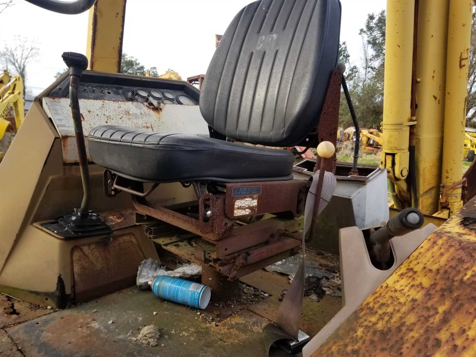
The structure of this powerful machine relies on a set of essential elements that ensure its effective operation in various construction and excavation tasks. Each piece plays a crucial role in delivering stability, efficiency, and control during heavy-duty applications.
- Engine: The powerhouse that drives the entire system, offering the strength needed for digging and lifting.
- Hydraulic System: Responsible for the smooth and precise movement of attachments, ensuring accurate control and flexibility.
- Transmission: Transfers power from the engine to the wheels, allowing for controlled movement across different terrains.
- Loader Arm: Enables lifting and transporting heavy loads, providing the machine with its versatility in handling various tasks.
- Operator’s Cabin: The control center equipped with ergonomic features, ensuring the user can work efficiently and
Understanding the Hydraulic System Layout
The hydraulic configuration in heavy machinery plays a crucial role in ensuring efficient and smooth operation. At its core, the system relies on pressurized fluid to transfer power, allowing for the movement of different components. Key elements include pumps, valves, and actuators, all working together to deliver precise control and force distribution.
The system’s layout is designed to ensure optimal flow of hydraulic fluid, with specific routing to minimize energy loss. Each connection and pathway is carefully engineered to maintain the integrity of the system, preventing leaks and ensuring long-lasting performance in demanding environments.
Engine and Powertrain Diagram Breakdown
Understanding the layout of the engine and powertrain is essential for proper maintenance and troubleshooting. These components work together to deliver power efficiently, driving both the vehicle’s movement and its operational capabilities. By studying the system’s layout, mechanics can identify key sections that require attention, ensuring optimal performance.
The power unit includes intricate parts responsible for combustion, fuel delivery, and energy conversion, while the drivetrain handles the distribution of power to the wheels. Examining the relationships between these elements helps in understanding how they interact and depend on each other for smooth operation.
Exploring the Backhoe Arm Assembly
The arm structure plays a critical role in the overall functionality of excavation machinery, providing the necessary reach and leverage for digging operations. This component is designed to withstand heavy loads and repetitive motion, ensuring durability and efficiency in various soil conditions. Its configuration allows for precise control, making it essential for operators to understand how each part contributes to smooth operation.
Main Components of the Arm
The arm consists of several key elements that work together to deliver effective digging performance. These include hydraulic cylinders, joints, and linkages, all meticulously engineered to handle the high demands of construction work. Hydraulic systems provide the necessary force to move the arm, while pivot points ensure flexibility during operation.
Maintaining Arm Efficiency
Regular maintenance of the arm assembly is vital to prevent wear and tear. Proper lubrication of moving parts, inspection of hydraulic lines, and checking for any signs of metal fatigue are all important steps
Front Loader Structure and Details
The front loader is a crucial component in many heavy machinery setups, designed to facilitate various earth-moving tasks. Its robust structure and intricate details contribute to its efficiency and effectiveness in handling materials, making it a vital asset for construction and agricultural operations.
Main Components
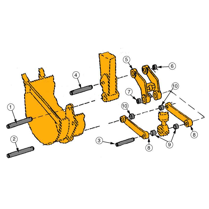
The primary elements of a front loader include the bucket, arms, and chassis. Each part plays a significant role in the loader’s overall functionality:
Component Description Bucket Used for scooping and transporting materials, designed in various sizes for different applications. Arms Connect the bucket to the machine and allow for lifting and lowering actions. Chassis The main body of the loader, providing stability and housing various systems. Operational Mechanisms
The operational mechanisms of a front loader involve hydraulic systems that enable smooth movement and precise control. These systems allow for the efficient lifting and dumping of materials, enhancing productivity on job sites.
Hydraulic Cylinder Placement and Function
The strategic arrangement of hydraulic actuators plays a crucial role in the efficiency and performance of heavy machinery. These components are designed to convert hydraulic pressure into mechanical force, enabling various movements essential for operation. Understanding their placement and functionality helps in maximizing the effectiveness of the equipment and ensuring smooth operation.
Placement Considerations
When positioning hydraulic cylinders, several factors must be taken into account, including the machine’s design, intended use, and operational requirements. Proper alignment ensures optimal force transfer and reduces wear on components. Each actuator must be installed in a way that facilitates effective movement while maintaining balance within the system.
Functionality and Importance
The main purpose of hydraulic actuators is to provide the necessary force for lifting, tilting, and extending various machine attachments. These cylinders operate under high pressure, which allows them to perform heavy-duty tasks with precision. Regular maintenance and proper placement are vital to sustaining their performance and prolonging the lifespan of the equipment.
Transmission and Axle Configuration
This section delves into the crucial elements of power transmission and axle design in heavy machinery. Understanding the configuration of these components is vital for optimal performance and efficiency in operation. The interplay between the transmission system and axles ensures that power is effectively transferred from the engine to the wheels, facilitating smooth movement and maneuverability.
Understanding Transmission Mechanics
The transmission system serves as the backbone of vehicle operation, allowing for the adjustment of speed and torque. Various types of transmissions, such as automatic or manual, provide flexibility in how power is delivered. Each design has its advantages, influencing factors like fuel efficiency and ease of control. Optimal gear ratios play a significant role in enhancing performance, particularly when handling heavy loads or navigating challenging terrains.
Axle Design and Functionality
The axle configuration is equally important, as it supports the weight of the machine and enables wheel rotation. Different axle designs, such as live axles or dead axles, cater to specific operational requirements. Durability and load-bearing capacity are critical considerations in selecting axle types, ensuring that they can withstand the rigors of demanding tasks while providing stability and control during movement.
Steering System Components Layout
The steering mechanism is crucial for maneuvering heavy machinery, ensuring precise control and stability during operation. Understanding the arrangement of various elements within this system is essential for effective maintenance and troubleshooting. Each component plays a specific role, contributing to the overall functionality and responsiveness of the vehicle.
Key Elements of the Steering Mechanism
The steering assembly consists of several critical parts, including the steering wheel, linkage, and hydraulic components. The steering wheel serves as the primary control interface for the operator, allowing for directional changes. The linkage transmits the operator’s input from the wheel to the steering system, while hydraulic components assist in enhancing the force applied, making steering more efficient and responsive.
Importance of Proper Configuration
Ensuring the correct layout of these elements is vital for maintaining optimal performance. Misalignment or wear can lead to reduced control and handling issues. Regular inspections and adjustments help to sustain the integrity of the steering system, providing safe and efficient operation in various conditions.
Braking Mechanism Parts Breakdown
The braking system of heavy machinery is crucial for ensuring safe operation and effective control. Understanding the components involved in this mechanism is essential for maintenance and troubleshooting. Each element plays a significant role in the overall functionality, contributing to the efficiency and reliability of the equipment.
Below is a detailed breakdown of the key elements within the braking system:
Component Name Description Brake Pedal The lever used by the operator to engage the braking system. Brake Cylinder Converts the mechanical force from the pedal into hydraulic pressure. Brake Pads Friction materials that press against the brake rotor to slow down or stop the machine. Brake Rotor The disc that the brake pads clamp onto to create friction and reduce speed. Brake Lines Hoses that carry hydraulic fluid from the cylinder to the brake components. Master Cylinder A device that generates hydraulic pressure in the braking system. Cabin and Operator Controls Diagram
This section provides a comprehensive overview of the interior layout and the control mechanisms utilized by operators. Understanding these elements is crucial for efficient handling and operation of the machinery. Proper familiarity with the arrangement and function of each component enhances safety and productivity on the job site.
Overview of Control Elements
The operator’s area is designed for maximum accessibility and comfort. Key features include:
- Steering wheel for directional control
- Control levers for hydraulic operations
- Pedals for throttle and braking functions
- Dashboard with essential monitoring instruments
Ergonomic Design Features
The cabin is equipped with various ergonomic elements to support the operator during long working hours:
- Adjustable seating for personalized comfort
- Ample legroom for ease of movement
- Sound insulation to reduce operational noise
- Climate control options for a comfortable environment