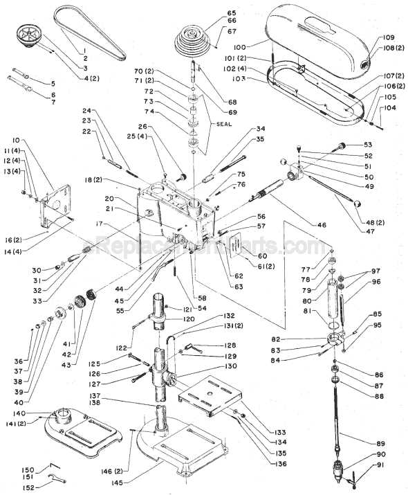
The proper maintenance and understanding of key mechanical assemblies are vital for ensuring smooth operation and extending the lifespan of industrial equipment. A detailed exploration of internal elements offers valuable insights into how these systems function and fit together seamlessly.
When familiarizing yourself with specific mechanical layouts, it becomes easier to identify potential wear points and anticipate necessary repairs. Each component, whether large or small, plays a crucial role in maintaining precision and efficiency throughout daily operations.
This guide aims to shed light on the structural composition of machinery, providing clarity on the arrangement of critical elements. Understanding their interconnect
Essential Components Overview
This section provides an in-depth look at the key mechanical elements that ensure optimal performance of a vertical machining tool. Each piece plays a crucial role in maintaining precision and stability during operation, making it essential to understand their placement and function.
Main Structural Elements
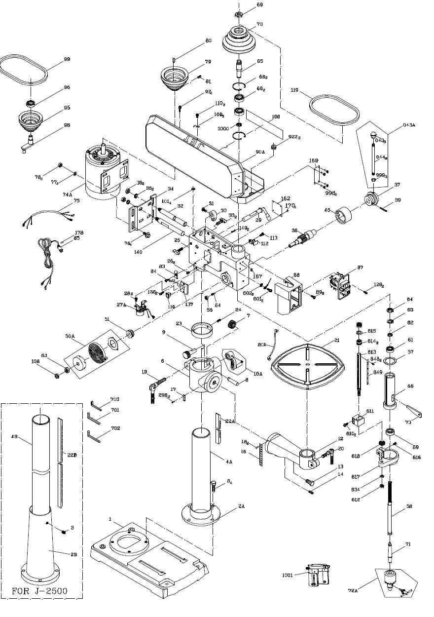
- Support Column: A vertical beam that offers stability and secures the upper sections in place.
- Worktable: An adjustable surface where materials are positioned and clamped for processing.
- Base Platform: The foundation that keeps the entire setup firmly anchored.
Mechanical and Motion Control Systems
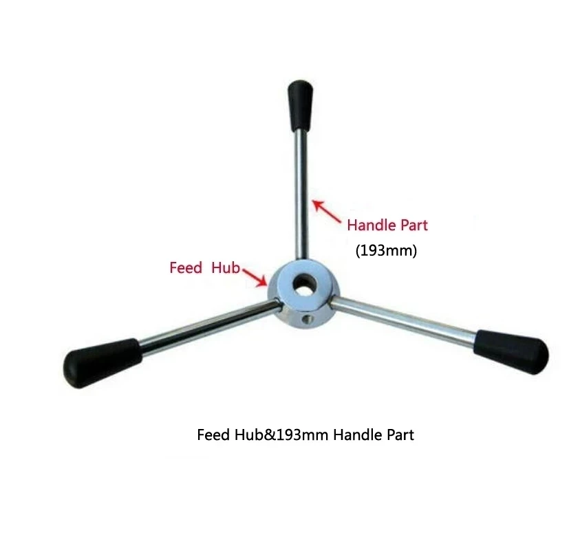
Main Components Overview
This section provides a general insight into the essential elements that ensure the proper functioning of a vertical boring tool. Each part plays a significant role in enabling efficient operation and accurate results, contributing to both performance and precision.
Component Description Base A sturdy platform that provides stability and anchors the entire structure. Column A vertical support structure connecting the base to the upper components, ensuring alignment and rigidity. Worktable An adjustable surface that holds materia How the Spindle Works
The spindle is a key element in machinery designed to create rotational movement. It allows precise transfer of energy to various attachments, ensuring smooth and controlled motion. This mechanism plays a vital role in equipment where steady rotation is required for effective operation.
Rotation and Power Transfer
The spindle’s primary function is to convert motor-generated energy into rotational force. It maintains alignment and stability during operation, minimizing vibrations. Bearings within the assembly reduce friction, contributing to a seamless and efficient rotation process.
Connection with Attachments
The spindle is designed to accommodate different tools or accessories, providing secure mounting and easy interchangeability. This adaptability
Understanding the Pulley System
The pulley mechanism plays a crucial role in transferring motion and adjusting the speed of rotating components. By manipulating the position of belts across grooved wheels, the system ensures smooth operation and precise control over the rotational force.
Pulleys are designed to change the speed and torque, providing flexibility for different tasks. When the belt moves between larger and smaller wheels, it shifts the rotational speed, balancing power and precision. This process allows the system to adapt efficiently to various requirements.
The alignment of the pulleys and tension of the belt are key factors for optimal performance. A well-maintained pulley system reduces wear on components, minimizes vibrations, and ensures consistent output. Proper adjustment extends the lifespan of the mechanism, preventing unnecessary strain.
Functions of the Quill Assembly
The quill assembly plays a crucial role in the operation of various machines by enabling controlled vertical movement. It ensures precision during tasks that require steady motion along a single axis, contributing to accuracy and stability.
A key function of the quill is to guide the spindle during its travel, maintaining alignment throughout the process. This helps prevent deviations that could affect performance. The assembly also allows for depth adjustments, ensuring consistent outcomes for tasks that require repeatable motions.
Additionally, the quill mechanism often incorporates return springs or similar components to restore the spindle to its starting position after use. This automatic retraction ensures smoother operation and minimizes the need for manual resetting, enhancing efficiency in repetitive tasks.
Types of Chuck and Their Uses
In various machining applications, the type of chuck employed plays a crucial role in determining the efficiency and precision of tasks. Chucks are essential components that secure cutting tools or bits, enabling effective operation across different projects. Understanding the various kinds of chucks available can help users select the most suitable option for their specific needs.
Key Types of Chucks
The most common types of chucks include keyless, keyed, and specialty chucks. Keyless chucks allow for quick and easy bit changes without the need for additional tools, making them ideal for tasks requiring frequent tool swaps. Keyed chucks, on the other hand, provide a tighter grip and are preferred in applications demanding higher torque. Specialty chucks cater to specific needs, such as holding unconventional bit shapes or sizes.
Choosing the Right Chuck
When selecting a chuck, factors such as the type of material being worked with, the required precision, and the frequency of bit changes should be considered. A well-chosen chuck not only enhances the performance of the machine but also ensures safety and efficiency during operation.
Switches and Electrical Controls
This section delves into the various components responsible for regulating electrical flow and ensuring the safe operation of machinery. Understanding these elements is crucial for maintaining functionality and performance in any equipment that utilizes electrical power.
Electrical controls encompass a range of devices that manage the power supply, enabling users to operate the machinery effectively. These components include switches, relays, and circuit breakers, each playing a vital role in the overall system.
Component Description Switches Devices that allow users to turn the power on or off, controlling the operational status of the equipment. Relays Electromechanical switches that control a circuit by a low-power signal, enhancing safety and efficiency. Circuit Breakers Automatic switches designed to protect electrical circuits from overload or short circuits by interrupting the flow of electricity. Adjusting the Depth Stop Mechanism
The depth stop feature is essential for achieving consistent and precise results during woodworking tasks. Properly setting this mechanism ensures that the tool can make cuts to a predetermined depth, allowing for greater control and accuracy in various projects.
Understanding the Mechanism
The depth stop mechanism typically consists of several components that work together to limit the downward travel of the cutting tool. Familiarizing yourself with these parts will aid in effective adjustments. Key elements include:
- Stop collar: This component is adjusted to set the maximum depth of the cut.
- Adjustment screw: This allows for fine-tuning of the depth setting.
- Locking lever: It secures the position of the stop collar to prevent unwanted movement.
Steps to Adjust the Depth Stop
- Loosen the locking lever to allow movement of the stop collar.
- Slide the stop collar up or down to the desired position.
- Tighten the locking lever to secure the collar in place.
- Test the adjustment by making a trial cut on a scrap piece of material.
- If necessary, repeat the process for further fine-tuning.
By carefully following these steps, users can enhance their woodworking accuracy and achieve the desired results consistently.
Table and Base Configuration
The arrangement of the platform and support structure is crucial for ensuring stability and precision during various tasks. A well-designed base enhances the overall functionality, allowing for smooth operation and effective material handling. Proper alignment and sturdy construction contribute significantly to achieving accurate results.
The platform is typically adjustable, enabling users to customize its height according to their specific requirements. This feature facilitates easy access to the workpiece, accommodating different sizes and shapes. Additionally, an expansive surface area provides ample space for placing materials, enhancing workflow efficiency.
The base is designed to provide optimal stability, often featuring reinforced legs and a solid foundation. This configuration minimizes vibrations and prevents unwanted movement during use. A robust base is essential for maintaining precision, particularly in detailed applications where accuracy is paramount.
Replacing Belts and Bearings
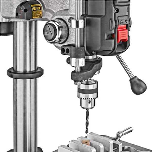
Maintaining optimal performance in any machinery often requires attention to components that experience wear over time. This section focuses on the importance of replacing essential elements such as drive belts and supporting elements, which play a critical role in ensuring smooth operation and reducing friction. Regularly inspecting and updating these components can prevent unexpected breakdowns and enhance the longevity of the equipment.
Signs of Wear
Identifying indicators of degradation is crucial for timely replacements. Common symptoms include unusual noises, vibrations, and decreased efficiency during operation. If the drive system struggles to maintain speed or if there are visible signs of fraying or damage on the belts, it is essential to address these issues promptly.
Replacement Process
To effectively replace these components, first, ensure the machinery is disconnected from any power source. Begin by removing the housing or cover to access the internal mechanisms. Carefully detach the worn belts and bearings, taking note of their arrangement for accurate reinstallation. Installing new belts and bearings should be done with precision, ensuring they are properly aligned and tensioned to avoid future complications.
Exploring the Motor Specifications
The efficiency and performance of any machinery largely depend on its motor specifications. Understanding the characteristics of the motor can provide insights into the overall functionality and reliability of the equipment.
Key specifications to consider include:
- Power Rating: The motor’s power output, typically measured in horsepower (HP) or watts (W), indicates its capability to handle various tasks.
- Voltage Requirements: The voltage rating is crucial for ensuring compatibility with electrical systems, impacting performance and safety.
- RPM (Revolutions Per Minute): This measurement reflects the speed at which the motor operates, influencing the speed of the attached tools.
- Type of Motor: Different types of motors, such as induction or brushless, offer varying benefits in terms of efficiency and maintenance.
- Torque: This parameter indicates the rotational force generated by the motor, affecting the ability to tackle heavy materials.
By analyzing these specifications, users can make informed decisions regarding the suitability and performance of the machinery for their specific needs.
Proper Lubrication of Moving Parts
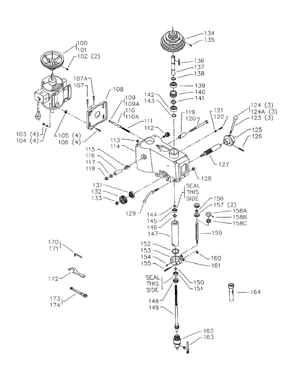
Ensuring the effective functioning of mechanical equipment requires attention to the maintenance of its moving components. Proper lubrication is essential for reducing friction, preventing wear, and extending the lifespan of the machinery. By regularly applying appropriate lubricants, operators can enhance performance and minimize the risk of breakdowns.
Types of Lubricants
Various lubricants are available for use, including oils, greases, and specialized fluids. The choice of lubricant depends on factors such as the operating environment, the materials involved, and the specific requirements of the equipment. Oils are typically used for high-speed applications, while greases provide better adhesion and protection in slower-moving systems.
Application Techniques
Applying lubricant correctly is just as crucial as selecting the right type. Ensure that all moving parts are accessible and clean before application. Using a clean cloth or applicator, apply the lubricant evenly to prevent accumulation and ensure thorough coverage. Regularly scheduled maintenance checks can help identify areas that require additional lubrication.
Troubleshooting Common Mechanical Issues
Mechanical devices can experience various issues that hinder their functionality. Identifying and resolving these problems is crucial for maintaining efficiency and ensuring safety during operation. This section will explore common complications and offer guidance on how to effectively address them.
1. Unusual Noises: If you hear grinding, squeaking, or rattling sounds, it may indicate a lack of lubrication or misalignment of components. Inspect the machinery for worn-out parts and apply the appropriate lubricant to moving elements to restore smooth operation.
2. Inconsistent Movement: If the mechanism does not move smoothly, check for any obstructions or debris that may be causing resistance. Ensure that all moving parts are clean and free from blockages. Additionally, examine belts and pulleys for wear and tear.
3. Overheating: Excessive heat can result from prolonged use or insufficient cooling. Ensure that ventilation is adequate and inspect the motor for signs of damage. If overheating persists, consider reducing the load or increasing break intervals.
4. Vibration: Excessive vibration can lead to premature wear of components. Ensure that the base is stable and secure. Check for any loose screws or fasteners, and tighten them to minimize movement.
5. Electrical Issues: If the equipment fails to power on, inspect the electrical connections and fuses for faults. Verify that the power supply is functioning correctly, and replace any damaged components to restore normal operation.