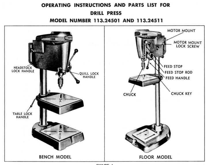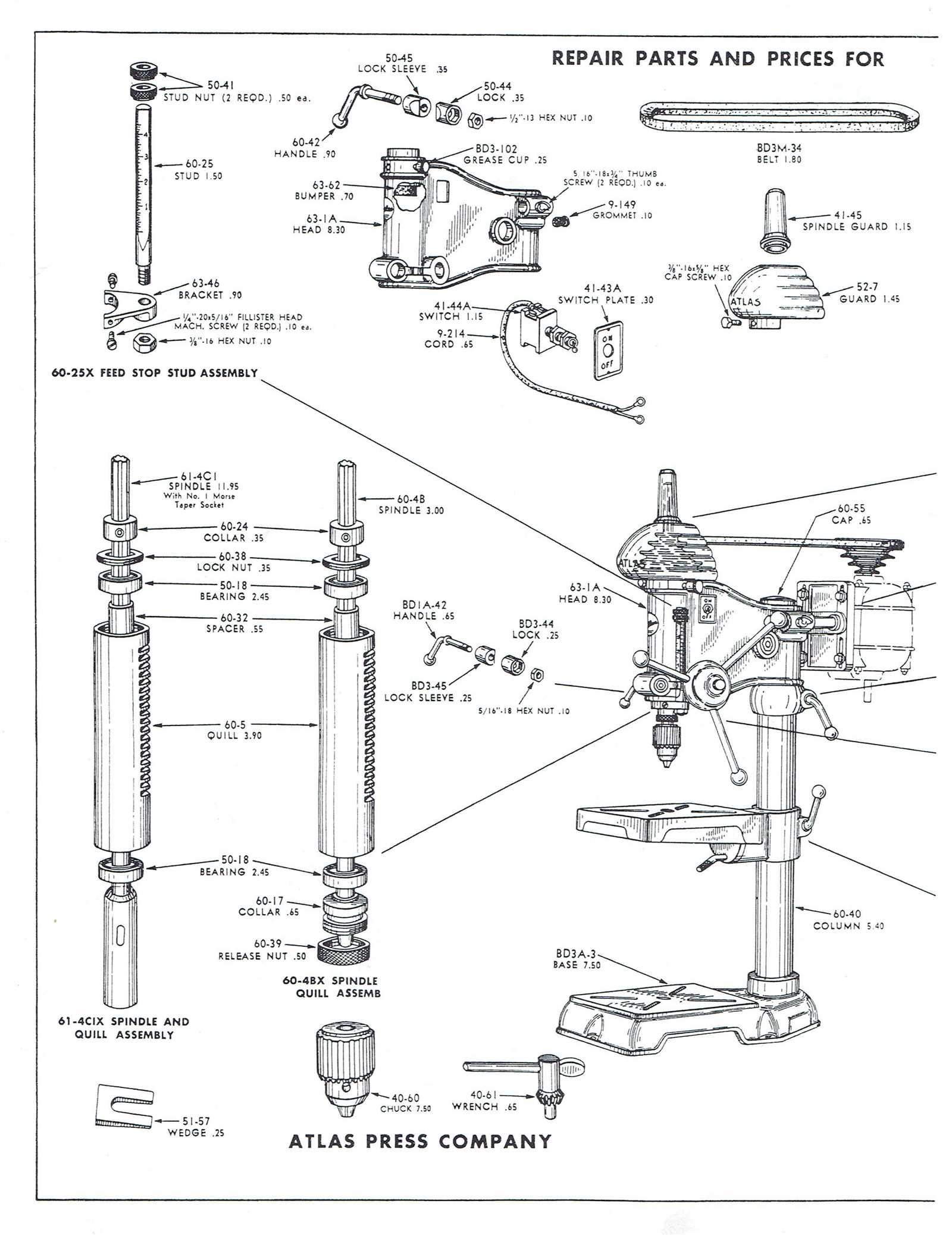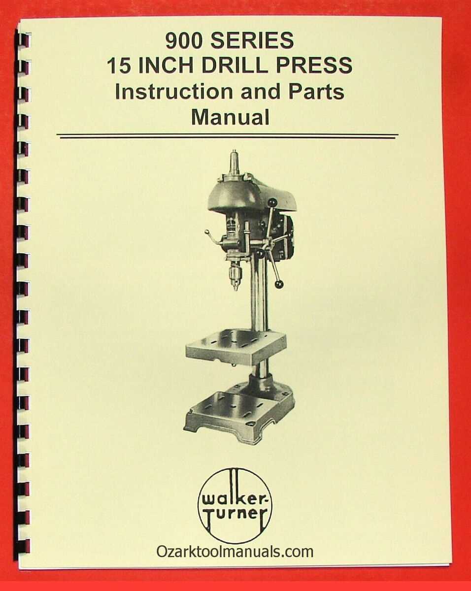
The mechanical assembly of a typical workshop tool consists of numerous components working together to deliver precise and effective results. To fully comprehend how each element operates, it is crucial to visualize their arrangement within the system. This section aims to offer a detailed overview of how these elements interact and function within the larger framework.
Each element in the setup serves a specific purpose, contributing to the tool’s overall functionality. Some components manage rotational movements, while others handle alignment and stability. By breaking down these different elements, one can better grasp the significance of each and how they contribute to the tool’s efficiency.
With this knowledge, you will not only improve your understanding of the system’s operation but also be better equipped to maintain and troubleshoot issues that may arise during use.
Understanding the Drill Press Components
The mechanics of this equipment rely on various interconnected elements that work in unison to achieve precise functionality. By examining each component, one can better appreciate how the system operates as a whole. These parts must be aligned and maintained to ensure the equipment performs optimally in different tasks.
Main Operational Elements
Each section of the machine plays a vital role in its overall function. From the control mechanisms to the power delivery system, understanding these components is essential for proper use and maintenance.
Key Structural Elements
The core framework of this equipment provides stability and support. Certain structural components are designed to withstand significant forces, ensuring that the machine remains steady during use, even under heavy workloads.
| Component | Description |
|---|---|
| Depth Limiter | Device that restricts the maximum depth of cut. |
| Locking Knob | Fastener used to secure the depth setting. |
| Measurement Indicator | Markings that help visualize the set depth. |
To adjust the depth stop, first loosen the locking knob. This will allow you to move the depth limiter freely. Set the desired depth by aligning the limiter with the measurement indicator. Once the correct position is achieved, tighten the locking knob securely to maintain the setting during operation.
Regular checks and adjustments are advisable to account for tool wear and material variations. By maintaining precise control over the cutting depth, you can enhance both the accuracy of your tasks and the overall quality of the finished products.
Motor and Belt System Explained
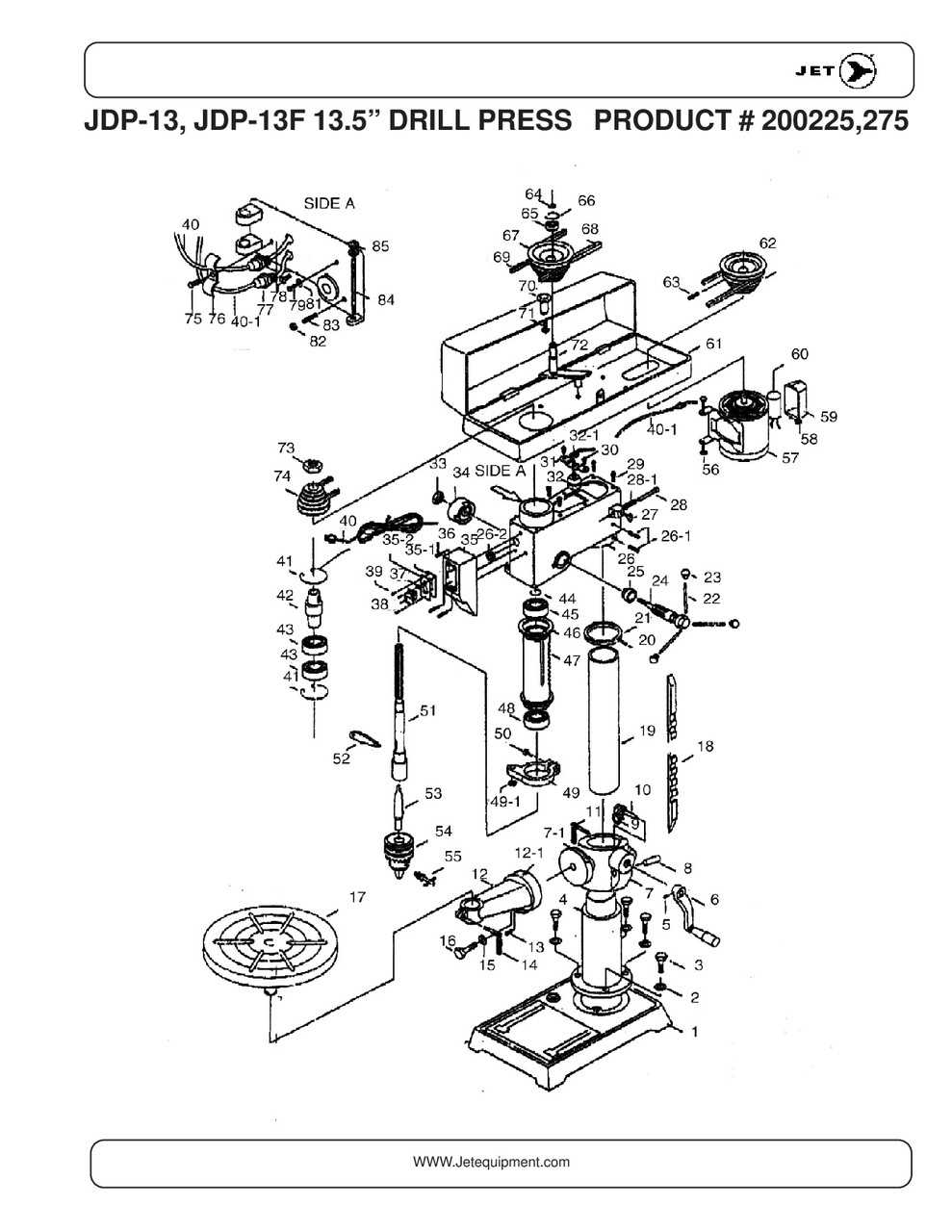
The motor and belt system serves as a vital component in various machinery, providing the necessary power and motion for operation. This mechanism works by transferring energy from the motor to the functional elements, enabling efficient performance across a range of tasks.
Electric motors play a crucial role in this setup, converting electrical energy into mechanical energy. They come in different types and sizes, tailored to meet the specific requirements of the machinery. The choice of motor influences the overall efficiency, torque, and speed capabilities of the system.
Connected to the motor is the belt system, which consists of one or more belts that facilitate the transfer of power. These belts are typically made from durable materials to withstand wear and ensure reliable operation. The tension of the belt is essential; it must be adjusted correctly to avoid slippage while allowing smooth movement.
In essence, the combination of the motor and belt system enables seamless operation, significantly impacting the performance and productivity of the equipment. Understanding how these components interact helps users maintain their machinery effectively and enhance its longevity.
Column and Its Role in Rigidity
The vertical support structure is essential for maintaining stability and precision during various operations. Its design significantly influences the overall strength and durability of the equipment, ensuring effective performance across different tasks.
Key functions of the vertical support structure include:
- Support: Provides a solid base that prevents wobbling or movement during use.
- Alignment: Helps in maintaining the correct alignment of tools and workpieces for accurate outcomes.
- Dissipation of Forces: Distributes the forces generated during operations evenly, reducing stress on components.
In summary, the vertical support structure is vital for enhancing the machine’s stability, thereby ensuring consistent results and prolonged lifespan. Its role cannot be underestimated in achieving optimal functionality and safety during use.
Handle Operation and Speed Control
The efficiency of a tool is significantly influenced by its operational mechanisms, particularly the control of movement and rotation. Understanding how the control mechanisms work can enhance both the precision and effectiveness of various tasks. This section delves into the functional aspects of the handles and the methods of regulating speed, emphasizing their importance in achieving optimal performance.
Functionality of Control Mechanisms
Control mechanisms are designed to facilitate smooth handling and ensure that users can adjust the operation according to specific needs. The handles enable users to maneuver the tool easily while allowing for fine-tuning of the angle and depth of operation. Proper use of these mechanisms is crucial for achieving accuracy in various applications.
Speed Regulation Techniques
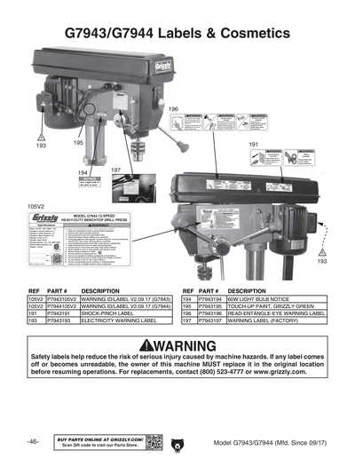
Effective speed regulation is essential for adapting the tool to different materials and tasks. The ability to adjust the rotational speed allows for greater versatility, enabling users to switch between tasks that require high speed and those that demand more control. Implementing various techniques for speed control ensures that the tool can perform optimally under diverse conditions.
Safety Features of Modern Drill Presses
Contemporary machines designed for precise drilling operations incorporate a variety of safety enhancements that prioritize user protection and operational reliability. These innovations aim to minimize risks associated with high-speed rotations and heavy components, ensuring a secure working environment.
Among the key safety features, one can find emergency stop buttons that allow for quick shutdown in critical situations. Additionally, improved shielding mechanisms help prevent accidental contact with moving elements, while built-in sensors can detect unusual conditions and halt the machine’s operation automatically.
| Feature | Description |
|---|---|
| Emergency Stop Button | A readily accessible control to halt operation immediately in emergencies. |
| Safety Guards | Protective barriers that shield operators from rotating components and debris. |
| Sensor Technology | Automatic systems that monitor performance and trigger shutdowns under unsafe conditions. |
| Variable Speed Control | Allows users to adjust speeds for different materials, reducing the chance of accidents. |
These advancements reflect a commitment to enhancing user safety and facilitating a more controlled working environment. As technology progresses, ongoing innovations in safety protocols will continue to evolve, further ensuring the well-being of operators.
Common Accessories for Enhanced Functionality
Enhancing the capabilities of a standard machine can significantly improve the efficiency and versatility of tasks. Various supplementary tools and attachments can transform basic functionality into advanced performance, making operations smoother and more precise.
These accessories are designed to extend the range of applications and increase user convenience. From specialized clamps to sophisticated depth gauges, each accessory plays a vital role in optimizing the workflow and ensuring high-quality results.
| Accessory | Description | Benefits |
|---|---|---|
| Adjustable Clamps | These secure workpieces firmly in place during operations. | Provides stability and precision, minimizing movement. |
| Depth Stop | Allows for consistent and repeatable depth control. | Ensures accuracy in hole depth, enhancing project quality. |
| Drill Chuck Key | Tool for tightening or loosening the chuck. | Facilitates quick bit changes for increased productivity. |
| Laser Guide | Projects a laser line for precise alignment. | Improves accuracy in positioning and reduces errors. |
| Table Extension | Increases the surface area for larger materials. | Enhances support for bigger projects, preventing instability. |
