When maintaining or repairing equipment, understanding the layout and relationship of its internal elements is essential. Knowing how the individual mechanisms interact with one another can greatly simplify the troubleshooting process and enhance the overall efficiency of repairs. This guide is designed to offer a clear view of how different mechanical elements are connected and function within the larger system.
Identifying each piece and understanding its specific role within the system is critical for anyone looking to ensure optimal performance. Whether you’re replacing or simply inspecting various mechanical elements, having a clear understanding of their structure and layout is key to a successful outcome. This guide will walk you through the critical aspects of the assembly and its functional relationships.
DW708 Parts Diagram Overview
This section provides a comprehensive breakdown of the key components and their arrangement within the device. Understanding how various elements are interconnected can assist in identifying areas that may require maintenance or replacement over time.
Below is a detailed list outlining the major structural and functional units:
- Motor Assembly – The core element that drives the operation, ensuring smooth functionality.
- Blade Mechanism – Responsible for precise and clean cutting performance.
- Adjustable Arm – Allows for customization of the angle and depth, improving versatility.
- Safety Guard – A protective feature designed to reduce risk during usage.
- Base Structure – Provides stability and support for all other components.
Each part plays a crucial role in ensuring efficiency, safety, and longevity of the tool. The arrangement of these components also facilitates
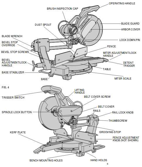
Main Components of the DW708
This section provides an overview of the key elements that make up the machine, focusing on the vital structures that contribute to its overall functionality. Each component works in harmony to ensure precise operation and long-lasting durability.
Cutting Mechanism
The cutting system is central to the machine’s operation, ensuring smooth and accurate performance. It features a powerful motor, a well-balanced blade, and a robust guard for safety. These elements are designed to handle various materials efficiently, providing a clean and precise cut.
Adjustment and Support Elements
Key adjustable parts allow for easy manipulation and control of the machine’s movements. This includes height adjustments, angle settings, and alignment features, all contributing to precision in different types of tasks. The support structures provide stability during operation, ensuring that
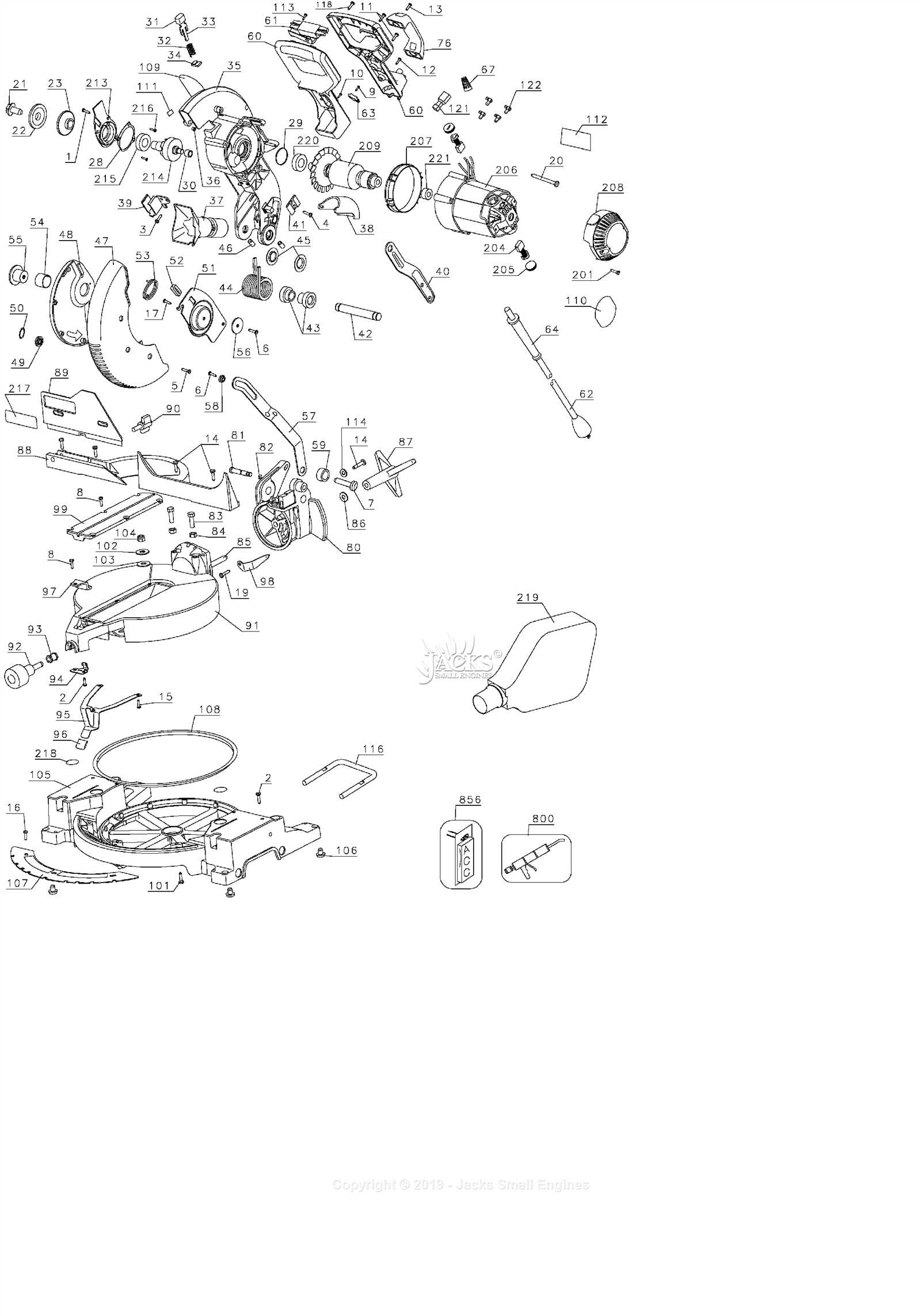
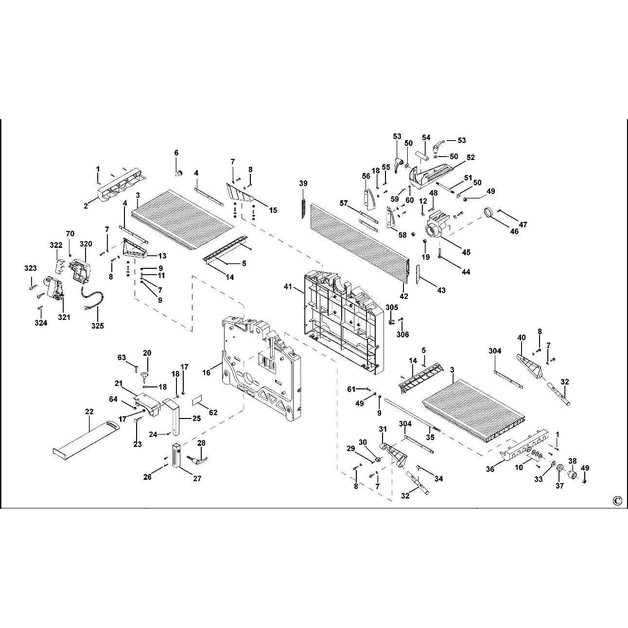
Exploded View of the DW708 Saw
The visual breakdown of the components in this cutting tool showcases its intricate design. Each element is carefully placed to ensure the tool operates efficiently and smoothly. This section provides a comprehensive look at how the various mechanical parts come together to form a fully functional cutting machine.
Key Components Overview
In this disassembled view, you can observe the arrangement of critical components like the motor, blade assembly, and support structures. These elements are essential for the tool’s performance and ensure precision during operation. Understanding the layout and interaction between these parts is important for maintenance and repairs.
Table of Key Elements
| Component | Function | Position |
|---|
| Component | Function | ||||||||||||||||||||||||||||||
|---|---|---|---|---|---|---|---|---|---|---|---|---|---|---|---|---|---|---|---|---|---|---|---|---|---|---|---|---|---|---|---|
| Mounting Section | Sec
Motor Housing and Drive MechanismThe motor housing serves as the protective cover for the internal components, ensuring the motor’s safe operation while keeping dust and debris away. The drive mechanism within this section transfers power efficiently, allowing for smooth and precise functionality. Together, they play a critical role in maintaining the overall performance of the tool. Construction and Materials
The housing is typically constructed from durable materials that provide insulation and protect against external damage. The design of the drive system incorporates gears and belts that ensure reliable movement and power transmission, minimizing wear over time. Each part is engineered to withstand high levels of stress and heat. Maintenance and Common IssuesRegular inspection of the motor housing and drive components is essential for preventing potential malfunctions. Over time, parts may experience wear or accumulate debris, which can affect performance. Proper maintenance involves cleaning, lubricating moving parts, and replacing worn-out elements to keep the mechanism running efficiently. Fence and Adjustment Features
The design and functionality of fencing systems play a crucial role in achieving precise cuts and enhancing overall efficiency in woodworking projects. These elements are essential for guiding the material securely, ensuring accurate measurements, and providing stability throughout the cutting process. By focusing on the adjustment capabilities, users can tailor the setup to meet specific requirements, resulting in improved accuracy and a seamless workflow. Adjustability for Precision
The ability to fine-tune the fence position is vital for achieving precise angles and lengths. Many systems incorporate simple mechanisms that allow users to make quick adjustments without the need for additional tools. This feature not only saves time but also enhances the quality of the cuts, enabling users to replicate measurements consistently across various projects. Stability and Support
A well-designed fencing system offers excellent support for the workpiece, minimizing movement during operation. Features such as anti-slip materials and adjustable locking mechanisms contribute to a secure setup, reducing the risk of errors. This stability is particularly important when working with larger materials, as it ensures safety and accuracy throughout the cutting process. Base and Mounting System DetailsThe foundation and attachment framework play a crucial role in ensuring stability and proper functioning. These components are designed to provide robust support and facilitate secure connections, which are essential for optimal performance and user safety. In this section, we will explore the various elements that constitute the base and mounting system. The base typically includes a sturdy platform that serves as the primary support structure, often made from durable materials to withstand wear and tear. The mounting system comprises brackets and fixtures that enable secure attachment to other components or surfaces, ensuring alignment and balance during operation. Moreover, the design of the base and mounting system is tailored to enhance usability, allowing for adjustments and flexibility in setup. Features such as quick-release mechanisms and adjustable height options contribute to user convenience, making it easier to achieve the desired configuration. Understanding these elements is vital for anyone looking to maintain or troubleshoot their equipment. A well-designed base and mounting system not only improves functionality but also extends the lifespan of the entire assembly. Handle and Switch ComponentsThis section delves into the essential elements responsible for controlling operation and maneuverability in various devices. These components play a pivotal role in ensuring smooth functionality and user interaction, allowing for precise adjustments and settings during use. The handle serves as the primary interface for users, providing a comfortable grip and facilitating easy handling. It is designed to offer stability and control, often featuring ergonomic shapes to reduce strain during prolonged usage. The materials used in its construction ensure durability while maintaining a lightweight profile. Switch mechanisms, on the other hand, are crucial for activating or deactivating the device. They can come in various forms, including toggle switches, push buttons, or slide controls, each offering distinct tactile feedback and operational advantages. Proper functionality of these switches is vital, as they directly impact the user’s ability to manage the device effectively. Together, the handle and switch components form an integral part of the overall system, enhancing both usability and performance. Understanding their design and function can lead to better maintenance and improved user experiences. Guard System BreakdownThe guard mechanism is an essential component designed to enhance safety and functionality. It plays a crucial role in ensuring that the equipment operates smoothly while protecting users from potential hazards. Understanding its structure and various elements can significantly improve maintenance and operational efficiency. Key ComponentsThe primary elements of the guard system include a variety of protective features that work together seamlessly. These components are specifically engineered to provide reliable support and minimize risks during use.
Maintenance TipsRegular inspection and maintenance of the guard system are vital for optimal performance. Check for any signs of wear or damage, and ensure that all components are functioning as intended. Keeping the guard system in excellent condition not only prolongs its lifespan but also enhances user safety. Bevel and Miter Mechanism ComponentsThe bevel and miter mechanisms are essential for achieving precise angled cuts in various materials. These mechanisms are composed of several interconnected elements that work together to facilitate adjustments and ensure accuracy during operation. Understanding these components is crucial for maintaining the performance and longevity of the equipment. Key Elements
Several vital components make up the bevel and miter mechanisms. Each plays a significant role in enabling the smooth operation of the cutting tool. Here is a brief overview of the key parts involved:
Importance of Proper Maintenance
Regular maintenance of these components is essential for ensuring optimal performance. Keeping the mechanisms clean and well-lubricated can significantly extend their lifespan and enhance cutting accuracy. By understanding and caring for these key elements, users can maximize the effectiveness of their cutting tools. Common Replacement Parts GuideThis section provides an overview of frequently needed components for maintenance and repair tasks. Understanding these essential elements can help ensure optimal performance and longevity of your equipment. Below are key items you may consider replacing over time. Essential Components
Maintenance Tips
Maintenance and Assembly TipsProper upkeep and assembly of your equipment are essential for ensuring optimal performance and longevity. Regular checks and mindful handling during reassembly can significantly enhance the efficiency of the device and prevent common issues from arising. Here are some useful suggestions to keep in mind. Regular Maintenance Practices
To maintain functionality, it is crucial to perform routine inspections and cleaning. This involves checking for any signs of wear or damage and addressing them promptly. Regularly cleaning moving parts can prevent buildup that may hinder performance. Always refer to the manufacturer’s guidelines for specific maintenance intervals and recommended cleaning methods. Assembly GuidelinesWhen reassembling your device, take care to follow a systematic approach. Ensure that all components are in good condition before starting. Organize parts to avoid confusion during assembly. Use appropriate tools to secure connections firmly without over-tightening, as this can lead to damage.
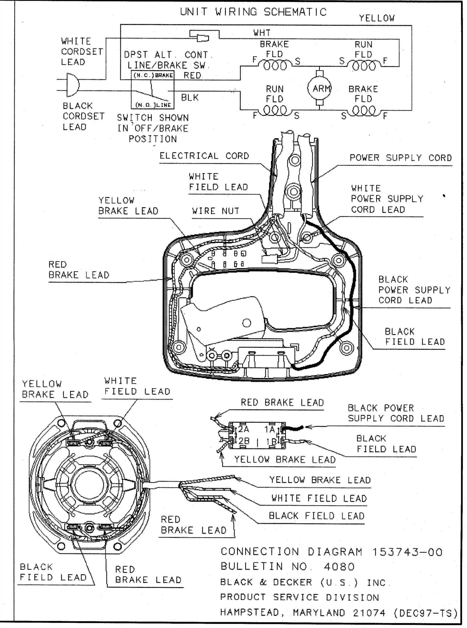
Understanding the Wiring DiagramThis section aims to clarify the intricacies of the electrical schematic associated with your device. By exploring the connections and components depicted in the illustration, you will gain a deeper understanding of how the system operates and the relationship between various elements. Key Components and Their Functions
Interpreting Connections
|
