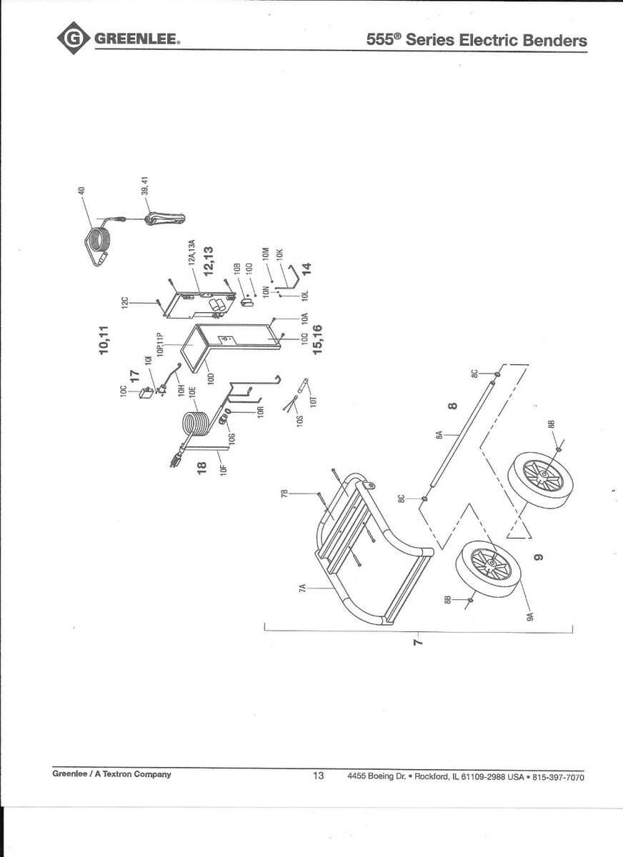
In this section, we explore the intricate setup and structure of various mechanical systems. The focus is on providing a clear and thorough understanding of how different elements come together to create an efficient and functional system. By gaining insight into these setups, one can better comprehend the way each component interacts with others.
Through a detailed overview, we highlight the critical connections and configurations. Understanding these connections helps in the maintenance and troubleshooting of the entire mechanism, ensuring everything operates smoothly and effectively. Each element plays a crucial role, and knowing its place and function is essential for anyone working with such equipment.
Essential aspects like assembly alignment, functionality coordination, and the placement of individual pieces are all covered in this discussion. This detailed breakdown aims to equip users with the knowledge needed to identify and understand each segment’s significance in the overall framework, thus enhancing the ability to manage and maintain such systems efficiently.
Understanding the Greenlee 555 Bender
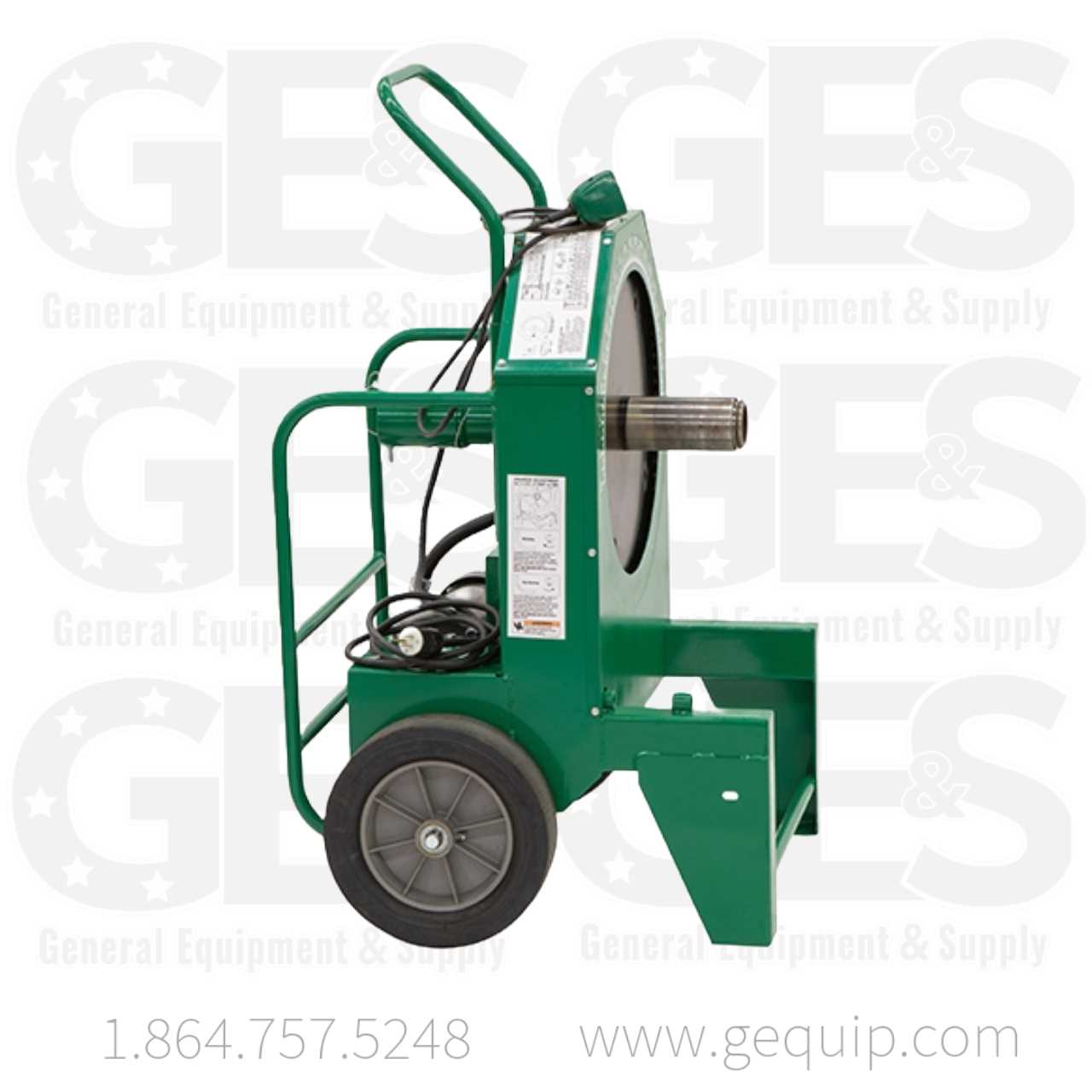
In this section, we’ll explore the functionality and key features of an advanced conduit forming tool. This equipment is designed for professionals who need precision and efficiency when shaping various types of materials. By examining its core components and operation methods, users can maximize their results and improve their workflow.
Main Functions and Capabilities
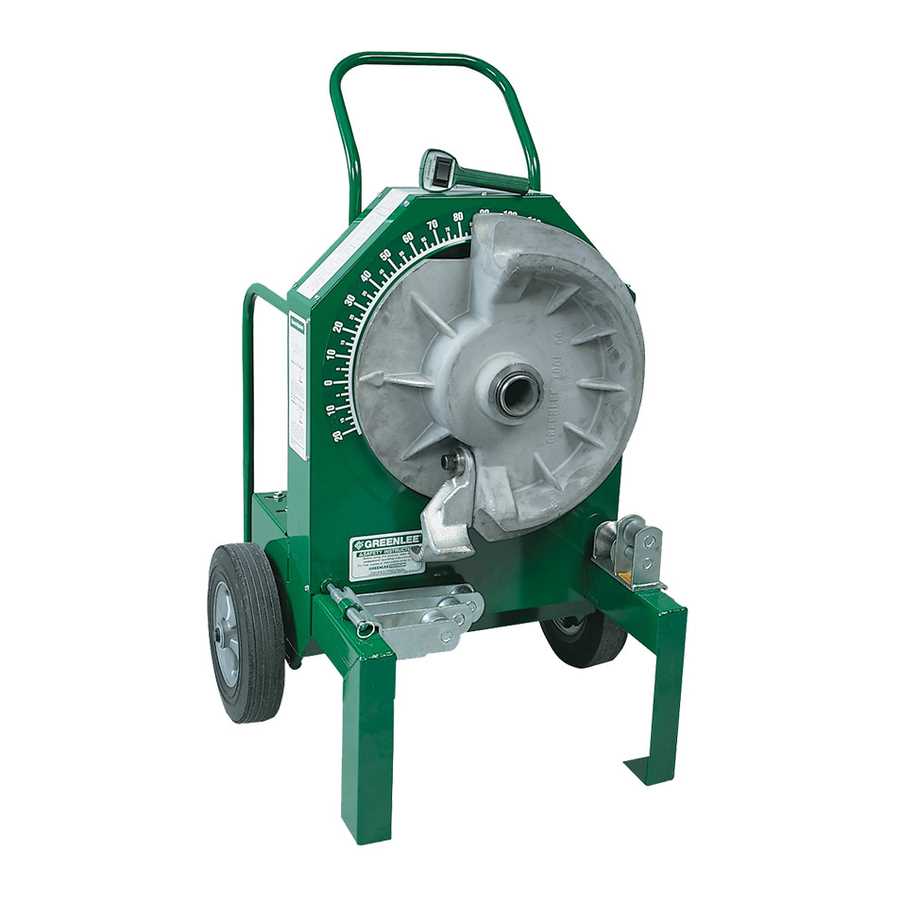
The tool is equipped with adjustable settings that allow users to customize angles and curves, ensuring accurate shaping for different applications. The versatility of the equipment makes it suitable for bending pipes and tubes of various diameters, which is crucial in complex installations.
Components and Setup
The device includes several key modules that work together to deliver consistent performance. Understanding how these parts interact can help users achieve precise results and maintain the equipment for long-term use. Proper setup is essential to avoid errors and ensure smooth operation throughout the bending process.
Key Components of the Greenlee 555
The machine in question is built from various essential elements, each contributing to its precise operation and reliability. Understanding these elements is crucial for maintaining efficiency and achieving the best results during use.
- Control Panel: This section allows the operator to manage and adjust settings for the entire process. It provides intuitive controls for precise adjustments.
- Drive Motor: The power source responsible for initiating movement, ensuring consistent speed and force during operation.
- Roller Assembly: This mechanism supports and guides materials through the machine, ensuring a smooth and accurate movement.
- Support Stand: Provides stability to the entire unit, allowing it to handle heavy loads and maintain balance during operation.
- Safety Switches: These components are crucial for user protection, stopping the machine immediately in case of any unexpected situation or overload.
How the Bending Mechanism Works
The bending mechanism is designed to transform metal pipes and tubes into precise shapes and angles. This process relies on a system that coordinates several components to apply controlled force, ensuring that the material bends smoothly without damage. Understanding how this mechanism functions helps to achieve consistent and accurate results in various bending applications.
Key Components Involved
The system includes several essential parts that work together to perform the bending operation efficiently. Each element plays a critical role in guiding, pressing, and forming the material. Below are the primary components typically involved:
- Drive System: Provides the necessary power and motion for the bending process. It may be hydraulic or electric, delivering the force required to bend the material.
- Forming Die: The die shapes the material as it is pressed against it, determining the bend radius and angle. It is critical to use the appropriate die size for the material being shaped.
- Clamping Mechanism: This secures the material in place during the bending process, ensuring stability and preventing slippage.
- Roller Set: Helps guide and support the material as it moves through the bending process, maintaining alignment and precision.
Steps in the Bending Process
- The material is first positioned and clamped securely within the system to prevent movement during the operation.
- The drive system activates, moving the forming die into place to apply pressure and create the desired bend.
Common Replacement Parts Overview
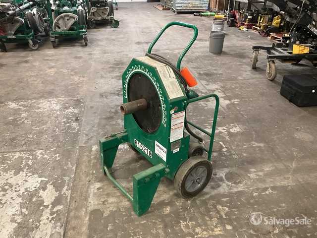
This section provides an overview of frequently swapped components and essential elements that ensure the efficient functioning of equipment. Understanding these key elements can help maintain the longevity and reliability of the machinery, enabling smoother operations and reducing downtime.
Essential Components
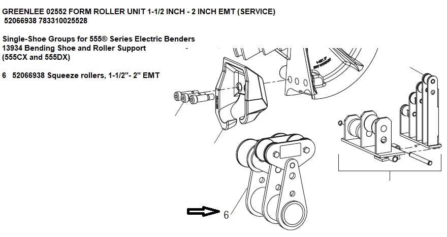
Several crucial components require regular inspection and occasional replacement to maintain the system’s performance. These include items responsible for supporting movement, ensuring proper alignment, and those that experience wear and tear during usage. By monitoring and replacing these parts as needed, users can enhance the durability and consistency of their equipment.
Wear-and-Tear Elements
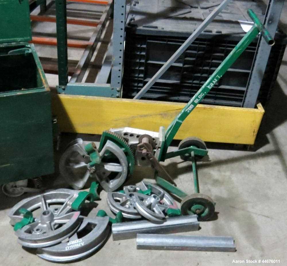
Wear-and-tear elements are parts that naturally degrade with usage. These might include connectors, guides, or seals that are exposed to continuous motion or friction. Periodic maintenance and timely replacement of these components are crucial to avoid operational issues and extend the lifespan of the machinery.
Identifying Electrical System Elements
Understanding the various components within an electrical setup is crucial for ensuring safety and functionality. Recognizing these elements allows for accurate assembly, maintenance, and troubleshooting. Knowing how to identify and differentiate these parts can prevent common issues and enhance the efficiency of any electrical task.
The main components often include conductors, connectors, and protective devices. Conductors, typically wires, carry electrical currents between different sections of the system. Connectors link these wires, forming a continuous pathway for the flow of electricity. Protective devices, such as fuses or circuit breakers, serve to safeguard the system by preventing overloads or short circuits.
Additionally, understanding control elements is vital. These may include switches, relays, and controllers that regulate the operation and flow within the system. Proper identification of these elements ensures that the setup operates smoothly and can be adjusted when necessary.
Maintenance Tips for Longevity
Ensuring the durability and optimal performance of your equipment requires consistent care and attention. Regular maintenance not only extends the lifespan of your tools but also enhances their efficiency, reducing the likelihood of unexpected failures.
1. Regular Cleaning: Keep your equipment free from dirt and debris. Accumulated grime can lead to wear and tear, affecting performance. Use a soft brush or cloth to wipe down surfaces after each use.
2. Lubrication: Apply appropriate lubricants to moving parts as specified in the manufacturer’s guidelines. This helps minimize friction, preventing damage and ensuring smooth operation.
3. Inspection: Conduct periodic checks for any signs of wear, corrosion, or damage. Early detection of issues can prevent costly repairs and downtime.
4. Proper Storage: Store tools in a dry, secure location. Avoid exposure to harsh weather conditions that could lead to rust or other forms of deterioration.
5. Follow Usage Guidelines: Always adhere to the recommended usage instructions provided by the manufacturer. Using equipment for purposes outside its intended design can cause damage and shorten its lifespan.
By incorporating these practices into your routine, you can ensure that your tools remain in excellent condition, providing reliable performance for years to come.
Safety Features and Their Functions

Ensuring user safety is paramount in any machinery or equipment. Various safety mechanisms are integrated into tools to protect operators from potential hazards while enhancing operational efficiency. Understanding these features and their roles can significantly contribute to a safer working environment.
Among the essential safety features found in such equipment are emergency shut-off systems, which instantly deactivate the tool in case of an unforeseen incident. Additionally, protective guards serve as barriers to prevent accidental contact with moving parts, reducing the risk of injuries. Furthermore, indicators and alerts are implemented to notify users of operational status or maintenance requirements.
| Safety Feature | Function |
|---|---|
| Emergency Shut-off | Instantly stops operation to prevent accidents. |
| Protective Guards | Prevents accidental contact with moving components. |
| Operational Indicators | Alerts users to the current status and maintenance needs. |
| Ergonomic Design | Reduces user fatigue and enhances control during operation. |
By familiarizing oneself with these features and their functions, users can maximize safety and efficiency while minimizing the risk of accidents during operation.
Hydraulic System Parts Explained
Understanding the components of a hydraulic system is essential for effective operation and maintenance. These systems rely on fluid dynamics to transmit force and perform various tasks, making it crucial to know the individual elements that contribute to their functionality.
The hydraulic assembly typically consists of several key elements, each playing a vital role in the overall performance. Hydraulic cylinders are responsible for converting fluid pressure into mechanical force, allowing for movement and lifting. Hydraulic pumps generate the necessary pressure to circulate fluid throughout the system, ensuring that all components receive adequate power.
Valves are critical in controlling the flow and direction of the hydraulic fluid, enabling precise operation. They can be manually or automatically operated, depending on the system design. Another important element is the reservoir, which holds the hydraulic fluid, allowing for proper system pressure and fluid replenishment.
Additionally, filters help maintain the cleanliness of the hydraulic fluid, preventing contamination that could lead to system failures. Understanding these components and their functions can significantly enhance the effectiveness and longevity of hydraulic systems.
Upgrading Parts for Better Performance
Enhancing equipment efficiency is crucial for achieving optimal results in various applications. By selecting high-quality components and modernizing existing ones, users can significantly improve the overall functionality and lifespan of their tools. This section discusses effective strategies for upgrading elements to maximize performance.
One of the primary considerations when improving performance is selecting upgraded materials that offer greater durability and resilience. For example, using advanced alloys or composites can enhance strength and reduce wear over time. Additionally, ensuring compatibility with existing systems is essential to facilitate seamless integration and prevent operational issues.
| Component | Standard Material | Upgraded Material | Benefits |
|---|---|---|---|
| Frame | Steel | Aluminum Alloy | Lightweight and corrosion-resistant |
| Hinge | Plastic | High-Density Polyethylene | Increased flexibility and impact resistance |
| Motor | Standard Electric | High-Efficiency Electric | Improved energy consumption and torque |
| Wheels | Rubber | Pneumatic | Smoother operation over rough terrain |
Regular maintenance and timely upgrades not only enhance performance but also contribute to a safer working environment. By staying informed about new technologies and materials, users can ensure their equipment remains competitive and efficient in the long run.
Wiring Diagrams and Schematics
Understanding the layout of electrical connections is crucial for efficient and safe operation. Schematic representations provide a visual guide that simplifies the comprehension of complex electrical systems. These illustrations depict the arrangement and relationship between various components, ensuring that users can effectively troubleshoot and maintain their equipment.
Importance of Accurate Schematics
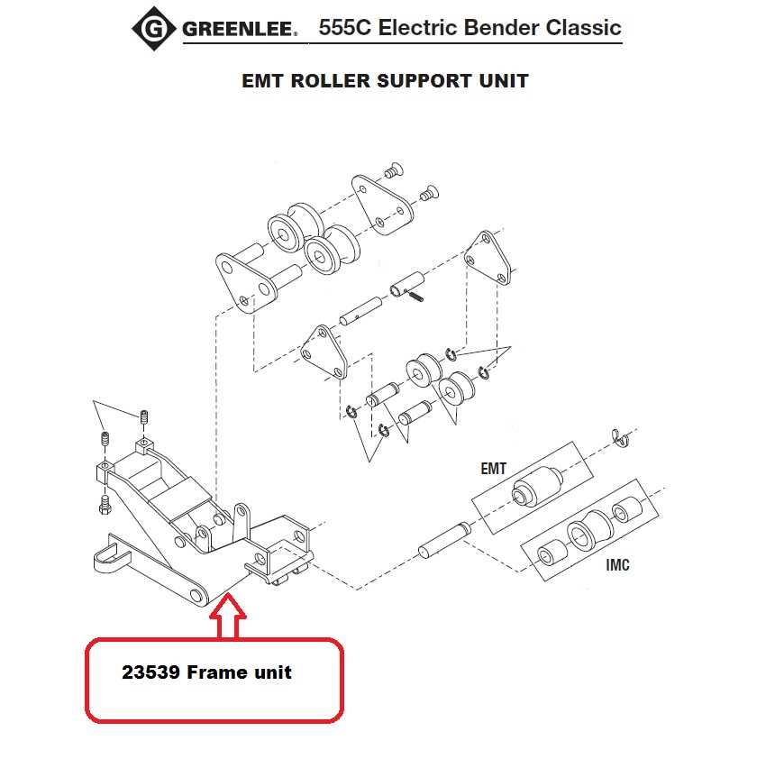
Accurate wiring representations are essential for preventing errors during installation and maintenance. They enable technicians to identify the correct connections and understand how different parts interact within the system. Misinterpretations can lead to malfunctions, which could result in costly repairs or safety hazards.
Common Components in Wiring Schematics
Several key elements are typically featured in wiring layouts. Familiarity with these components enhances comprehension and troubleshooting abilities. Below is a table highlighting common parts found in these representations:
| Component | Description |
|---|---|
| Resistor | Limits the flow of current in a circuit. |
| Capacitor | Stores and releases electrical energy as needed. |
| Switch | Controls the flow of electricity by opening or closing a circuit. |
| Connector | Joins two or more electrical circuits. |
| Ground | Provides a common return path for electric current. |
Troubleshooting Common Issues
Addressing frequent problems is essential for maintaining the efficiency and longevity of your equipment. Understanding potential challenges can help users identify and rectify issues promptly, ensuring smooth operation. Below are common difficulties encountered, along with effective solutions to mitigate them.
Common Problems
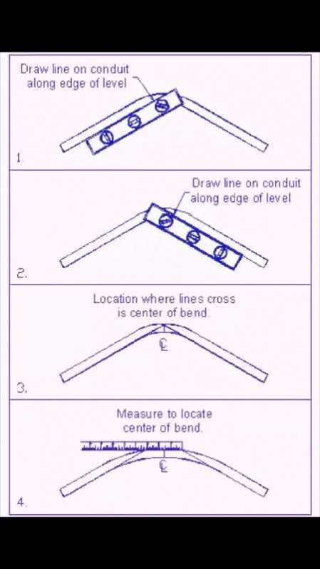
- Inconsistent bending angles
- Difficulty in achieving desired curvature
- Excessive wear on components
- Unusual noises during operation
Solutions
- Check for alignment issues; ensure that all parts are correctly positioned.
- Inspect components for signs of damage or wear; replace any faulty parts immediately.
- Lubricate moving parts to reduce friction and noise.
- Refer to the manual for calibration instructions to adjust bending settings.
By following these guidelines, users can effectively troubleshoot and resolve common challenges, ensuring optimal performance and durability of their equipment.