Safety Features: Built-in safeguards such as f
Battery Pack Structure and Positioning

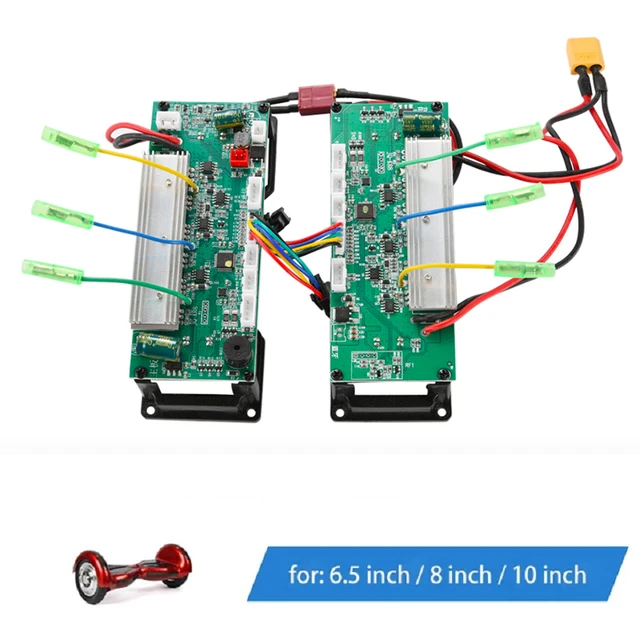
The energy storage unit plays a crucial role in ensuring efficient power supply and overall performance. Its design and layout are meticulously crafted to provide a stable and secure power source, while minimizing weight and maximizing space within the framework. Proper positioning of the power unit contributes to balanced weight distribution, enhancing stability and operational safety.
Typically, the energy source is housed in a compact, robust casing that safeguards it from external factors. The arrangement is carefully planned to align with the central components of the device, ensuring easy access for maintenance or replacement. The orientation of the unit also factors into heat dissipation, with adequate ventilation paths integrated into the surrounding design to prevent overheating during prolonged use.
Understanding the Gyroscope’s Role in Balancing
The ability of modern personal transportation devices to maintain balance relies heavily on specific components that monitor orientation and motion. Among these, a crucial element works to detect subtle shifts in direction and angle, ensuring the stability of the device. This mechanism enables real-time adjustments, allowing for smooth and controlled movement without the user having to manually correct their stance.
Gyroscopes are at the heart of this balancing system. They operate by measuring the rate of rotational movement along different axes, providing constant feedback to
Wheel Motors and Their Functionality
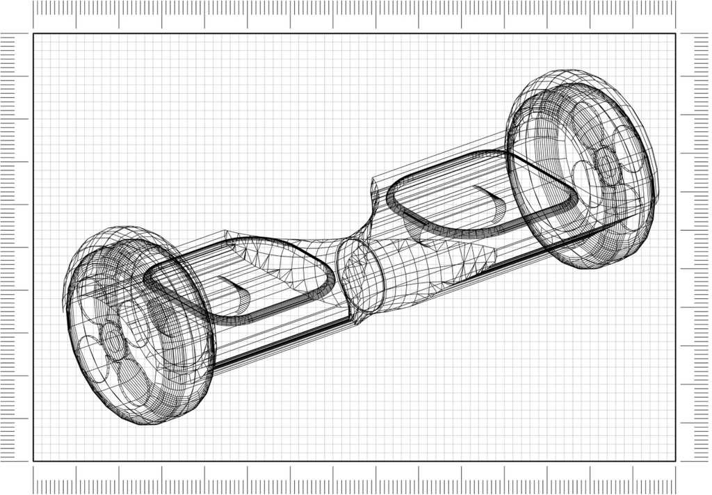
The driving mechanism of electric transportation systems relies heavily on the motors integrated into each wheel. These components are responsible for converting electrical energy into mechanical motion, providing the necessary propulsion for smooth and responsive movement. Their design and performance directly influence the overall riding experience, including speed, balance, and maneuverability.
Types of Motors
- Brushless DC Motors (BLDC): Known for their efficiency and durability, these motors use electronic controllers instead of brushes for commutation, reducing wear and enhancing performance.
- Brushed Motors: These are less efficient but simpler in design, with a brushed mechanism that wears out over time. They are often used in more cost-effective designs.
Motor Functionality
- Propulsion: The motors control the forward and backward movement by spinning the wheels in response to user input, whether via manual controls or automatic sensors.
- Speed Control: Motor output is regulated by varying the amount of electrical current, allowing for smooth acceleration and deceleration, crucial for safe operation.
- Balance Maintenance: The motors work in tandem to adjust the wheel speeds, helping to maintain stability, especially during turns or uneven surfaces.
Charging Port Location and Connectivity
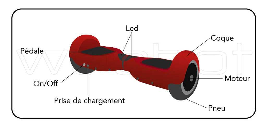
The charging interface is a critical element for maintaining the functionality of your device. Its position and the way it connects to the system influence both the ease of recharging and the overall safety of the operation. Proper identification of this location is essential for quick access and secure charging.
Port Placement
The charging input is typically situated in a convenient spot on the frame, often near the footrests or at the side of the unit. This location is chosen to ensure easy access while minimizing the risk of exposure to dirt or moisture, which could compromise its performance.
Connection Specifications
Connectivity to the charging system is established through a proprietary connector that ensures stable power transfer. It is vital to use the correct charging cable that matches the specifications to avoid potential issues with voltage or current flow, which could damage the internal circuits.
LED Lights and Display Indicators
Modern personal transport devices are equipped with a variety of visual signals to provide essential information to the rider. These indicators, often in the form of LED lights and screens, communicate everything from battery status to operational conditions. Understanding their functions is key to ensuring proper use and safety during rides.
Functionality of LED Lights
LED lights are commonly used to convey immediate information about the device’s status. These lights often serve to indicate power levels, speed modes, and potential errors. A typical setup may include multiple colors and flashing patterns to signify different statuses, making them intuitive for users to understand at a glance.
Display Indicators for Enhanced Monitoring
Display indicators provide a more detailed view of the device’s condition. They often feature symbols or numerical data to inform the rider about remaining battery life, system health, or error alerts. These displays ensure that the rider can keep track of important operational details in real-time, helping prevent malfunctions and ensuring smooth use.
| LED Light Color |
Meaning |
| Green |
Fully charged or operating normally |
| Yellow |
Medium battery level, monitor usage |
| Red |
Low battery or error, recharge or check for issues |
| Flashing Red |
Critical issue, immediate attention required |
Protective Casing and Exterior Shell Design
The external housing of any personal transportation device plays a crucial role in ensuring durability and safety. It not only shields internal components from environmental factors but also contributes to the overall aesthetic appeal and user experience. A well-designed enclosure balances form and function, offering protection while maintaining an appealing look.
Material selection is key in determining the performance of the exterior shell. Durable materials such as reinforced plastics or metals are commonly used to withstand impact, moisture, and other external stresses. The choice of materials ensures the device remains operational in various conditions without compromising its structural integrity.
The design of the casing also influences the ease of maintenance and repair. Accessible design features allow for quick troubleshooting and component replacement, while secure closures prevent dirt, dust, and moisture from entering the device, extending its lifespan.
Footpads and Pressure Sensor Arrangement
The footpads serve as the primary interface between the user and the movement system. Positioned strategically, these components ensure the user can control the motion and stability by applying varying pressure. The arrangement of these footpads is crucial in enabling intuitive control and responsiveness to user actions.
Pressure Sensor Functionality

The pressure sensors embedded beneath the footpads detect subtle shifts in weight distribution. These sensors translate the user’s movements into electronic signals, allowing for precise adjustments in the system’s balance and direction. Pressure sensitivity is key to ensuring a smooth and responsive experience during use.
Layout and Placement
The design of the footpad and sensor setup takes into account ergonomics and ease of use. The sensors are positioned to ensure optimal detection, allowing for a natural response to shifts in weight. Strategic placement enhances the user’s ability to maintain balance and execute turns effortlessly.
