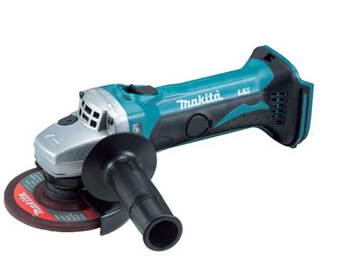
The efficient operation of any power tool depends on the integrity and arrangement of its internal components. Each part plays a crucial role in ensuring smooth performance and overall durability. Knowing how these elements come together can significantly enhance both maintenance and troubleshooting.
By familiarizing yourself with the layout of key elements, you gain a better understanding of how they interact and support each other. This insight is essential for extending the lifespan of your equipment, as it helps in identifying potential issues before they escalate.
Whether you’re looking to replace worn-out components or simply learn more about the tool’s construction, understanding the inner workings is a vital step in keeping everything running efficiently.
Makita BGA452 Parts Overview
This tool is composed of several key components that work together to provide efficiency and precision. Each element plays a critical role in ensuring smooth operation and durability, contributing to the tool’s reliability and performance. The design focuses on user convenience, making maintenance straightforward and replacement of elements simple.
Key elements include a sturdy motor that ensures power delivery, durable exterior parts for protection, and smaller functional pieces that support the overall functionality. These pieces are designed for easy assembly and disassembly, allowing users to maintain their tool without complications.
Main Components of the Makita BGA452
The structure of this handheld tool is designed to provide high performance and durability. Key elements ensure the efficiency and safety of the device, allowing it to tackle various tasks with precision and ease. These components work together to deliver consistent power and reliability during operation, enhancing the overall user experience.
Motor and Power Transmission
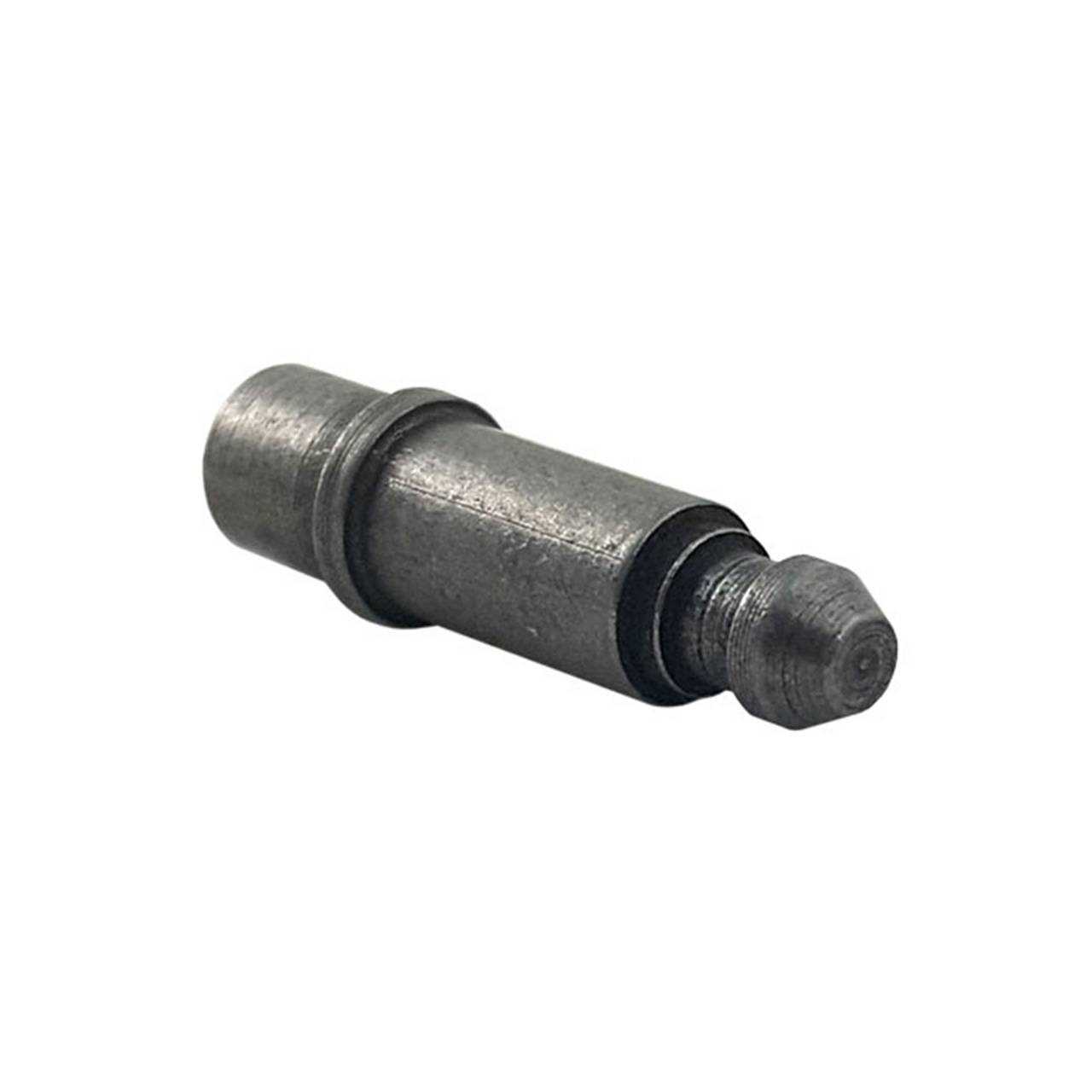
The heart of the device lies in its robust motor, which drives the entire system. This motor is responsible for converting electrical energy into the mechanical motion necessary for the tool’s function. Coupled with a reliable power transmission mechanism, it ensures smooth and controlled performance, even under demanding conditions.
Protective and Functional Features
Safety and durability are prioritized through integrated protective features. A specialized guard shields the working area, preventing damage and ensuring user safety. Additionally, ergonomic design elements contribute to ease of handling, reducing fatigue during prolonged use.
Understanding the BGA452 Motor Assembly
The motor assembly is the core of any power tool, providing the necessary energy to drive the device. Its complex design ensures smooth operation and durability during use. By understanding its components and how they interact, you can maintain efficiency and prolong the tool’s lifespan.
The motor unit consists of several interconnected elements, each playing a specific role in energy conversion and power output. Below is a breakdown of the main elements within this assembly:
- Armature: Converts electrical energy into mechanical rotation.
- Carbon Brushes: Transfer electrical current between stationary and moving parts.
- Field Coils: Generate the magnetic field required for motor rotation.
- Fan Blades: Help to cool the motor during operation, preventing overheating.
- Bearings: Reduce friction, ensuring smooth rotational movement.
Each part of the motor assembly works together to ensure reliable and powerful performance. Regular maintenance of these components is crucial for optimal tool functionality.
Exploded View of the Gear Housing
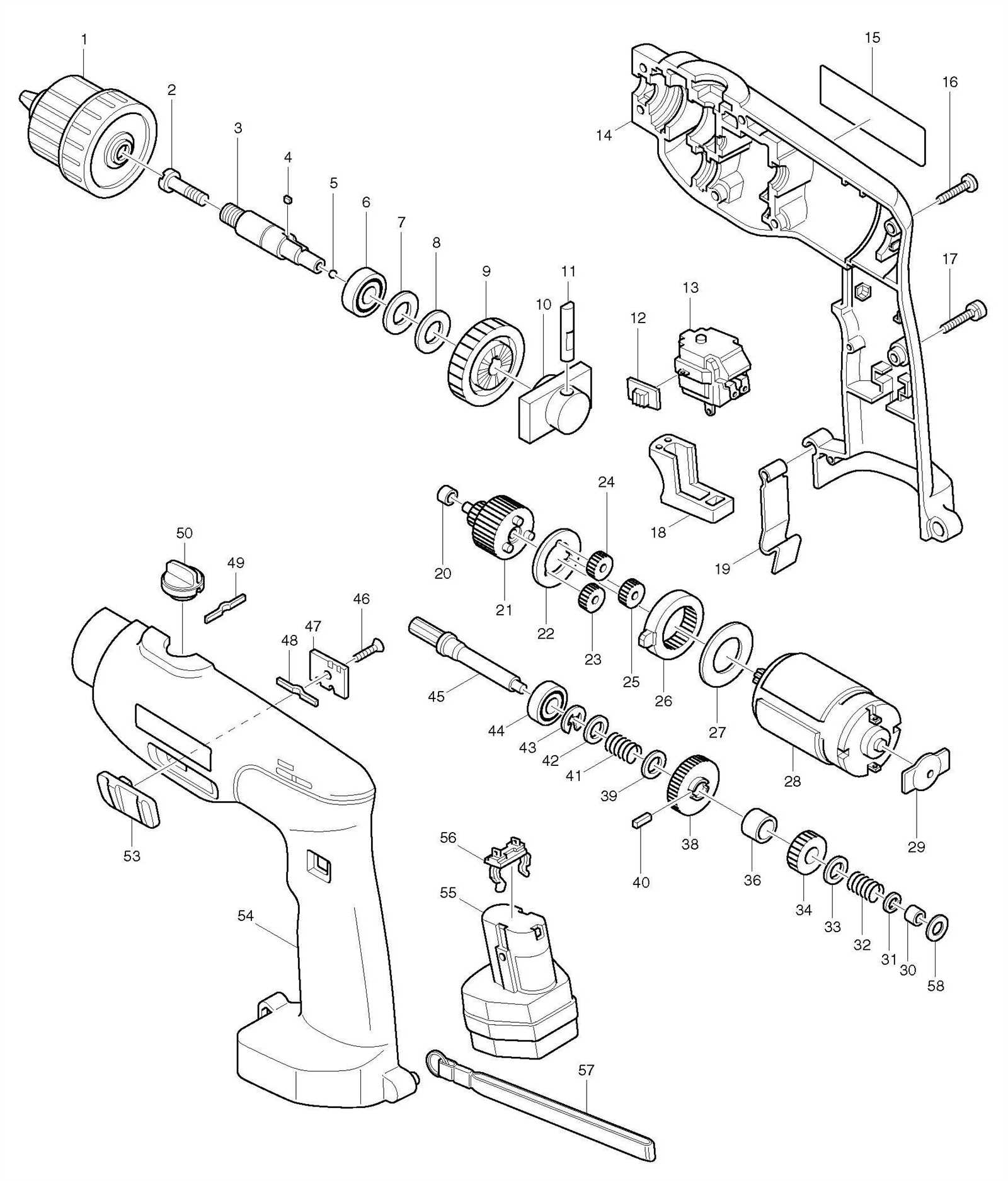
The gear housing section showcases the detailed structure of the internal mechanism, presenting a clear view of how its various components interconnect to ensure smooth operation. This breakdown helps in understanding the individual elements responsible for transmitting power efficiently through the device, allowing for proper maintenance and replacement when necessary.
Main Components in the Gear Housing
- Pinion: The small driving gear responsible for engaging larger components to initiate movement.
- Bearings: Positioned to support rotational movement, ensuring minimal friction during operation.
- Seals: Protect internal parts by keeping debris and other contaminants out of the housing.
Assembly Order and Functionality
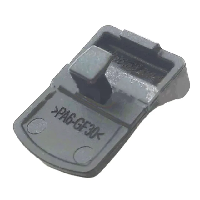
- The shaft connects to the pinion, transmitting force to the larger gears.
- Bearings ensure smooth rotation, while seals maintain a clean internal environment.
- The entire assembly operates as a cohesive unit, transmitting energy efficiently and allowing controlled movement.
Identifying the Bearings and Seals
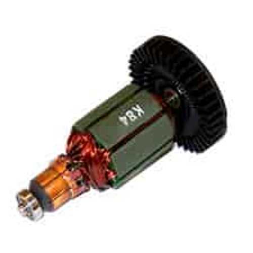
Bearings and seals are essential components in any rotating system, ensuring smooth operation and preventing wear over time. Understanding their location and role within a mechanical tool can help maintain its efficiency and prolong its lifespan. Proper identification of these parts ensures they are serviced or replaced accurately when necessary.
| Component | Function |
|---|---|
| Bearings | Support rotational movement, reducing friction between moving parts. |
| Seals | Prevent the ingress of contaminants and retain lubrication in moving components. |
Replacing the Carbon Brushes
Carbon brushes are essential components in many electric tools, responsible for conducting electricity to the motor. Over time, these brushes can wear out, leading to reduced performance or complete failure of the device. Regular inspection and timely replacement can enhance the longevity and efficiency of the equipment.
Signs of Worn Brushes
Identifying when to replace the carbon brushes is crucial for maintaining optimal functionality. Common indicators include:
| Indicator | Description |
|---|---|
| Reduced Power | Noticeable decrease in tool performance or power output. |
| Unusual Noises | Grinding or rattling sounds during operation may signal wear. |
| Frequent Overheating | Overheating of the tool can indicate poor electrical contact due to worn brushes. |
Replacement Steps
To replace the carbon brushes, follow these steps:
- Disconnect the tool from the power source to ensure safety.
- Remove the casing to access the motor area.
- Locate the carbon brushes, usually secured with screws or clips.
- Carefully detach the old brushes and replace them with new ones.
- Reassemble the casing and test the tool for proper operation.
Diagram of the Safety Guard Assembly
The safety guard assembly is a crucial component that enhances user protection during operation. Understanding its configuration and the role of each element is essential for maintenance and effective use. This section outlines the various components and their arrangement within the guard assembly, ensuring users are familiar with the safety features available.
Components of the Safety Guard
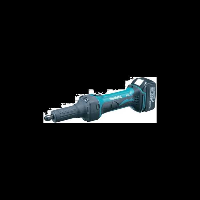
The assembly consists of several key parts, including the main guard, mounting brackets, and adjustment mechanisms. Each component plays a specific role in safeguarding the user from debris and potential hazards while providing flexibility in operation.
Functionality and Adjustment
Proper adjustment of the safety guard is vital for optimal performance. Users should regularly inspect the guard for any signs of wear and ensure that all components are securely fastened. Familiarity with the assembly allows for swift troubleshooting and maintenance, promoting safe operation.
Switch Mechanism and Internal Wiring
The functionality of a power tool heavily relies on its control system and wiring setup. This section explores the components responsible for activating the tool and facilitating the flow of electricity throughout its internal structure.
The switch mechanism serves as the primary interface for the user, allowing for the regulation of power. It typically comprises various elements that ensure reliable operation and safety. A well-designed switch provides not only ease of use but also contributes to the overall longevity of the tool.
Internal wiring plays a crucial role in connecting the switch to the motor and other essential parts. Properly arranged wiring minimizes the risk of short circuits and enhances the efficiency of energy transfer. Understanding the layout and organization of these wires is vital for troubleshooting and maintenance.
Overall, a well-functioning switch and robust internal wiring are integral to the effective operation of any power tool, influencing both performance and safety.
Disassembly of the Outer Casing
The process of removing the external shell of the device is crucial for accessing internal components for maintenance or repair. Understanding the steps involved will help ensure a smooth and efficient disassembly.
Before beginning, gather the necessary tools, such as a screwdriver and pliers, to facilitate the procedure. It’s important to ensure that the device is unplugged to avoid any electrical hazards.
| Step | Description |
|---|---|
| 1 | Remove any screws securing the outer casing. Use the appropriate screwdriver for this task. |
| 2 | Gently pry apart the casing sections, taking care not to damage any clips or connectors. |
| 3 | Once detached, set the casing aside and inspect for any visible wear or damage. |
Following these steps will ensure that the outer shell is removed safely, allowing access to the internal mechanisms for further examination or repair.
Commonly Replaced Parts in the BGA452
When working with this power tool, certain components are frequently substituted to maintain optimal performance and ensure longevity. Understanding which elements tend to wear out can help users quickly identify issues and make informed decisions about replacements.
Essential Components for Replacement
Several critical elements are often subject to replacement due to regular wear and tear. These include the following:
| Component | Function | Signs of Wear |
|---|---|---|
| Motor | Powers the tool for operation | Loss of power or unusual noises |
| Battery | Provides energy for operation | Decreased runtime or failure to charge |
| Trigger Switch | Controls the activation of the device | Intermittent operation or difficulty in switching on/off |
| Blade | Used for cutting tasks | Dullness or damage affecting performance |
Maintenance Tips for Longevity
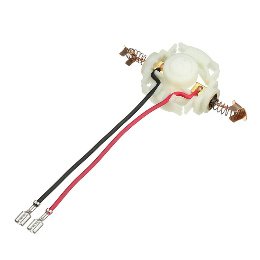
Regular maintenance of these components can enhance the tool’s performance and extend its lifespan. Users are encouraged to inspect the device frequently and replace any worn-out elements promptly.
Understanding the Tool’s Lock Button
The lock button on power tools serves a crucial function in enhancing user safety and control. It is designed to prevent accidental activation during operation, ensuring that the device remains secure when not in use. Familiarity with this feature is essential for anyone looking to maximize the efficiency and safety of their equipment.
Functionality and Importance
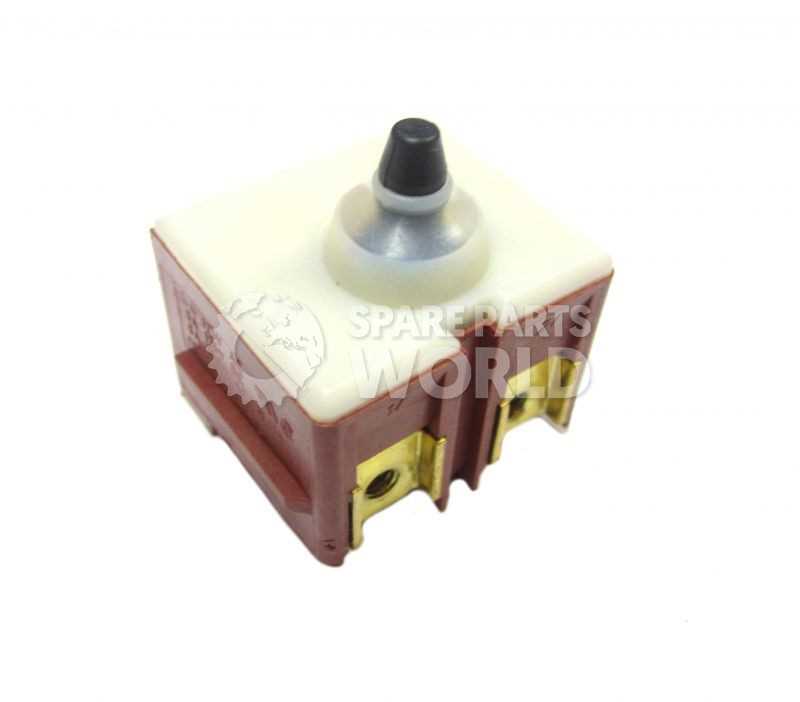
This control mechanism allows the user to disengage the power trigger, providing peace of mind, especially in work environments where tools are frequently handled. By engaging the lock, operators can safely transport or store the tool without the risk of unintentional operation. Understanding its placement and functionality can significantly impact overall user experience.
Operational Guidance
To effectively utilize the lock button, users should follow the manufacturer’s guidelines. Engaging and disengaging the lock mechanism should be done with care, ensuring the tool is not in operation. Regular checks for the functionality of this feature can prevent accidents and extend the tool’s lifespan.
| Action | Recommendation |
|---|---|
| Engaging Lock | Ensure the tool is off before engaging the lock button. |
| Disengaging Lock | Press the lock button firmly while squeezing the power trigger. |
| Routine Check | Inspect the lock button for wear and functionality during maintenance. |
Detailed View of the Spindle Assembly
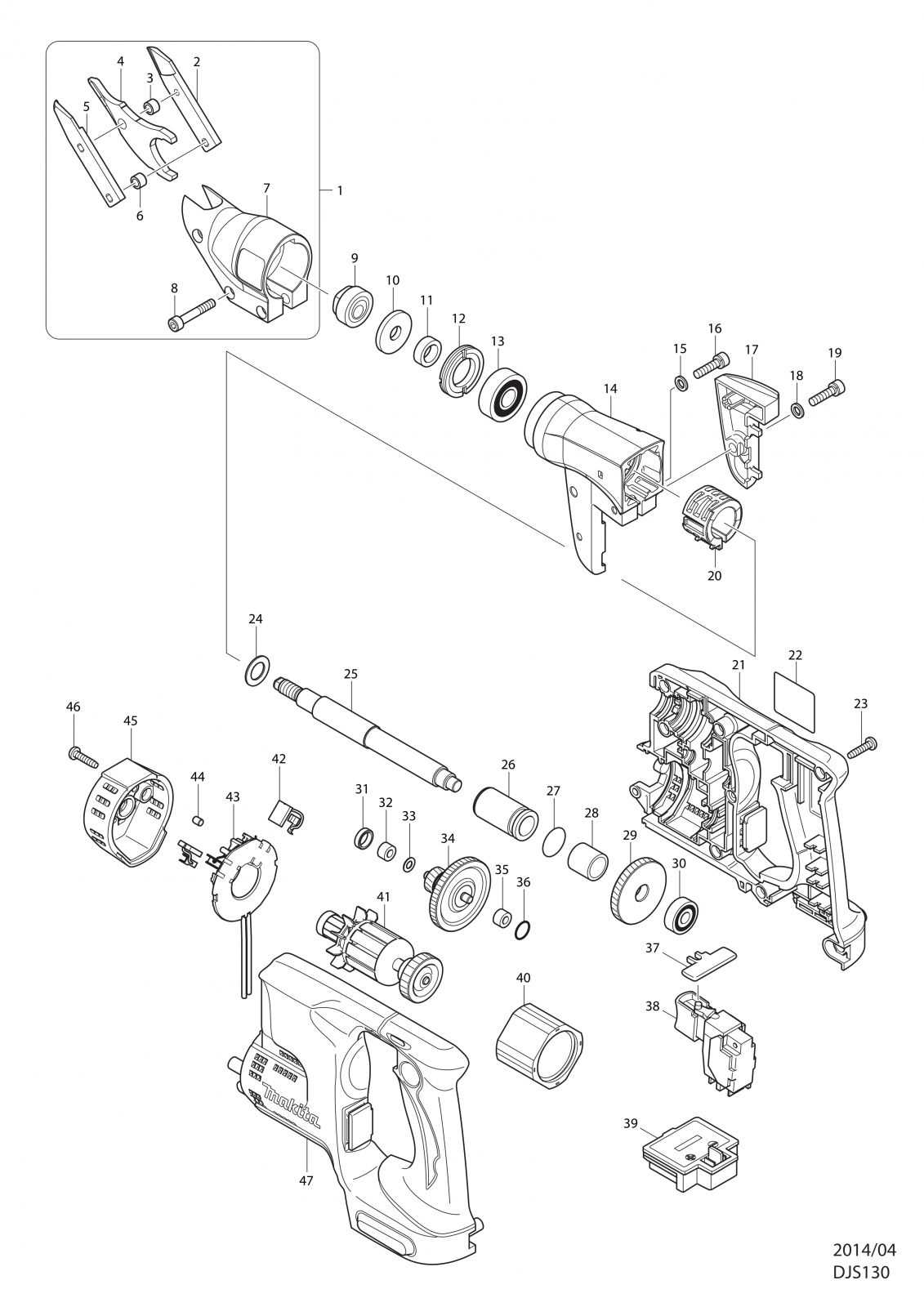
The spindle assembly is a crucial component in power tools, playing a significant role in the overall functionality and efficiency of the device. Understanding its structure and parts can aid in maintenance and repairs, ensuring optimal performance during operation.
This assembly typically includes several key elements that work together seamlessly. Below is a breakdown of these components, highlighting their functions and interactions.
| Component | Description |
|---|---|
| Spindle | The central shaft that rotates, transmitting power from the motor to the attached tool. |
| Bearings | These support the spindle, allowing it to rotate smoothly while minimizing friction. |
| Flange | A disc that secures the tool to the spindle, ensuring stability during operation. |
| Lock Nut | This fastens the flange and tool securely to the spindle, preventing any loosening during use. |
| Washer | Placed between the lock nut and the flange, it helps distribute pressure and reduce wear. |