When it comes to ensuring the long-term reliability of large machinery, it’s crucial to have a clear understanding of its essential components. Every mechanism, no matter its size or function, plays a vital role in the overall performance. Knowing how these elements work together can significantly extend the equipment’s lifespan and improve efficiency in daily operations.
Regular inspections and proper upkeep are vital for avoiding unexpected downtime. By familiarizing yourself with the key structural and functional parts, you’ll be better equipped to manage wear and tear, make timely replacements, and maintain optimal performance. In this article, we explore the critical aspects of heavy machinery and how each part contributes to seamless operation.
Understanding how to maintain these essential systems allows operators to spot potential issues early, ensuring safe and smooth operation. From mechanical linkages to hydraulic systems, every detail must be considered when maintaining heavy-duty machines.
Understanding the Massey Ferguson 236 Loader
To operate any heavy machinery efficiently, it’s essential to grasp the core features and functional aspects that define its use. This equipment is designed to handle a variety of tasks, from moving materials to assisting in larger construction projects. With a robust framework and specific attachments, it becomes a versatile tool for both agricultural and industrial environments.
Core Components and Functionality
At the heart of this machine lies a sturdy arm mechanism, designed to lift, transport, and deposit materials. The structure is built for stability, ensuring that it can handle different loads without compromising safety. Hydraulic systems power its movements, giving the operator full control over precision and strength during operation.
Maintenance and Longevity
Regular care is critical for extending the life of this equipment. Proper lubrication of moving parts, checking hydraulic fluid levels, and ensuring that the mechanical connections remain secure are all vital steps. Routine inspections not only prevent breakdowns but also enhance overall efficiency,
Main Components of the Loader
Understanding the essential parts of this type of machinery is key to ensuring its proper functionality. The overall structure is made up of various interconnected elements that work together to perform heavy lifting and transport tasks efficiently. Below is an outline of the most important mechanical segments, each playing a critical role in its performance.
- Frame: This foundational structure supports the entire assembly and provides stability during operation.
- Hydraulic System: Responsible for powering the movement, this system ensures that lifting and tilting actions are smooth and controlled.
- Lift Arms: These arms extend from the main body, allowing the equipment to raise and lower its load efficiently.
- Bucket: A large, scooping attachment designed for digging and carrying materials like soil, gravel, or debris.
- Control Valves: These components regulate the hydraulic flow, enabling precise manipulation of movements.
- Hydraulic System Overview
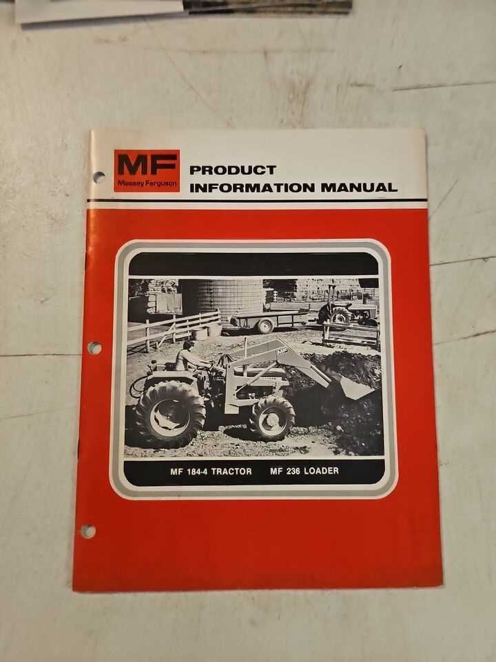
The hydraulic system plays a critical role in ensuring smooth and efficient operation in machinery. It is responsible for transmitting power through fluid pressure, allowing for precise control of various mechanical functions. By leveraging hydraulic energy, heavy equipment can perform complex tasks with minimal effort, providing the necessary force
Control Mechanisms and Levers
Operating heavy machinery involves the use of various levers and control systems that enable precise manipulation of different functions. These components ensure the operator can perform tasks with efficiency and safety, allowing seamless transitions between different movements and adjustments during work.
Main Control Levers
Primary levers are used to manage key operations, such as lifting, lowering, and adjusting equipment. They are strategically placed for easy access, making it simple for the operator to handle multiple tasks at once.
- Lift lever – regulates the vertical movement.
- Tilt lever – adjusts the angle of attachments.
- Directional control – shifts equipment forward or backward.
Auxiliary Controls
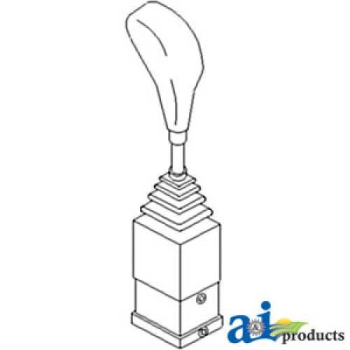
In addition to the main levers, auxiliary controls allow fine-tuning of equipment for more specialized tasks. These controls may vary depending on the type of attachments or additional features available.
- Hydraulic lever – modulates additional fluid-powered functions.
- Speed control – adjusts the rate of movement for more precision.
- Stabilizer control – ensures steady
Bucket Assembly Parts Breakdown
The breakdown of the bucket assembly reveals the key components that ensure smooth operation and durability. Understanding how each element functions in unison is essential for maintaining the efficiency and reliability of the system. This section outlines the main sections of the assembly, highlighting their importance and interactions.
Main Structural Components
The structure of the bucket consists of several critical elements designed to withstand heavy loads and rigorous tasks. These include the main frame, reinforced side panels, and attachment points that hold the system together, ensuring stability and resistance to wear. Proper maintenance of these components can prolong the lifespan of the entire unit.
Hydraulic Mechanism and Linkages
The hydraulic system and linkages are responsible for the movement and control of the bucket. This includes the cylinders, hoses, and mechanical arms that provide the necessary power for lifting, tilting, and securing the load. Regular inspection of these moving parts is crucial to avoid malfunction and ensure fluid performance.
Component Function Main Frame Front Arm Structure and Functions
The front arm assembly plays a crucial role in the overall functionality of a heavy-duty machinery unit. This component is designed to provide support and mobility, allowing for various tasks to be accomplished efficiently. Its structure encompasses multiple elements that work in unison, ensuring optimal performance during operation.
Key Features: The front arm is typically constructed from robust materials, providing strength and durability necessary for handling heavy loads. It consists of several joints and pivot points, which facilitate smooth movement and flexibility. The design often includes hydraulic cylinders that enhance lifting capabilities and control, allowing for precise adjustments.
Functions: One of the primary functions of the front arm is to elevate and lower attachments or implements. This capability is essential for tasks such as digging, lifting, or moving materials. Additionally, the arm’s structure enables it to reach various angles and heights, increasing its versatility in different work environments.
Overall, the efficiency of the front arm assembly significantly impacts the effectiveness of the machinery, making it an integral component for operators seeking to maximize productivity.
Lift Cylinder Parts and Maintenance
The lift cylinder is an essential component that plays a crucial role in the operation of heavy machinery. Understanding its structure and ensuring proper upkeep is vital for optimal performance. Regular maintenance helps prevent breakdowns and extends the lifespan of the equipment.
Key Components
- Piston: The main element that moves within the cylinder to generate lifting force.
- Rod: Connects the piston to the lifting mechanism, transferring the force effectively.
- Seal: Prevents hydraulic fluid leakage, ensuring efficient operation.
- Cylinder Body: Houses the piston and contains the hydraulic fluid necessary for movement.
- End Cap: Secures the components within the cylinder and facilitates the connection to the machinery.
Maintenance Tips
- Regular Inspections: Check for signs of wear, leaks, or damage.
- Fluid Checks: Ensure the hydraulic fluid level is adequate and free of contaminants.
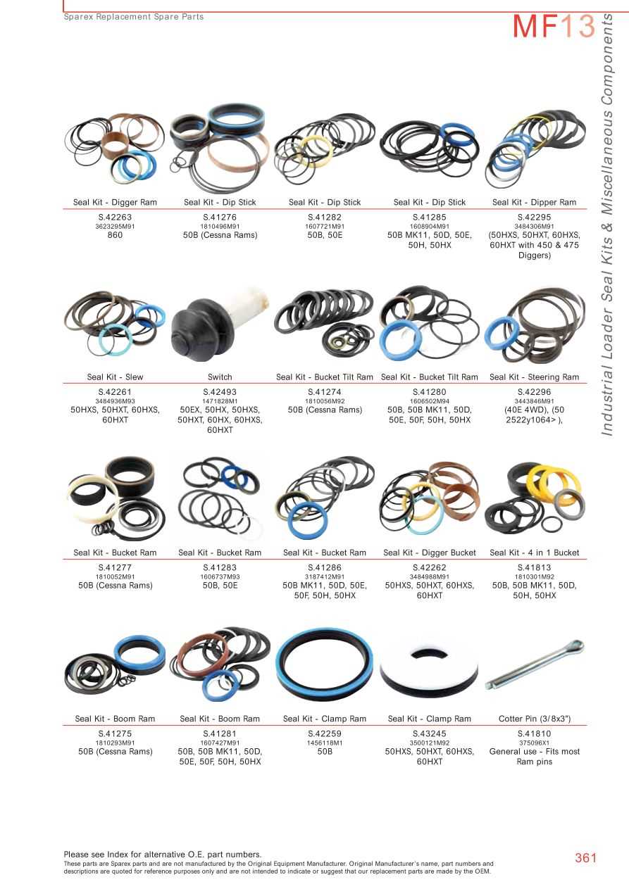
- Seal Replacement: Regularly replace seals to maintain pressure and efficiency.
- Cleaning: Keep the cylinder and surrounding areas clean to prevent debris from causing damage.
- Lubrication: Apply appropriate lubricants to moving parts as recommended by the manufacturer.
Rear Attachment and Mounting Points
The rear section of a machinery unit plays a crucial role in enabling various implements to be affixed securely. Understanding the attachment system and mounting configurations is essential for efficient operation and compatibility with different tools. This segment will explore the common features and arrangements found in the rear section.
When considering rear attachments, it is important to note the following key elements:
- Mounting Brackets: These are designed to facilitate the easy connection of various implements, ensuring stability and reliability during use.
- Connection Points: Specific locations where attachments can be affixed, providing versatility in tool selection and functionality.
- Alignment Features: These elements help in the precise positioning of attachments, reducing the risk of misalignment and enhancing performance.
- Hydraulic Connections: In many cases, fluid power connections are integral to operating certain implements, allowing for enhanced control and efficiency.
Proper maintenance and inspection of these areas are vital to ensure optimal performance. Regular checks can help identify wear and tear, ensuring that all components function as intended and prolonging the lifespan of the equipment.
In conclusion, familiarizing oneself with the rear attachment system and mounting points is essential for anyone utilizing this type of machinery. This knowledge not only enhances operational efficiency but also ensures safety and reliability during various tasks.
Common Replacement Parts for the Loader
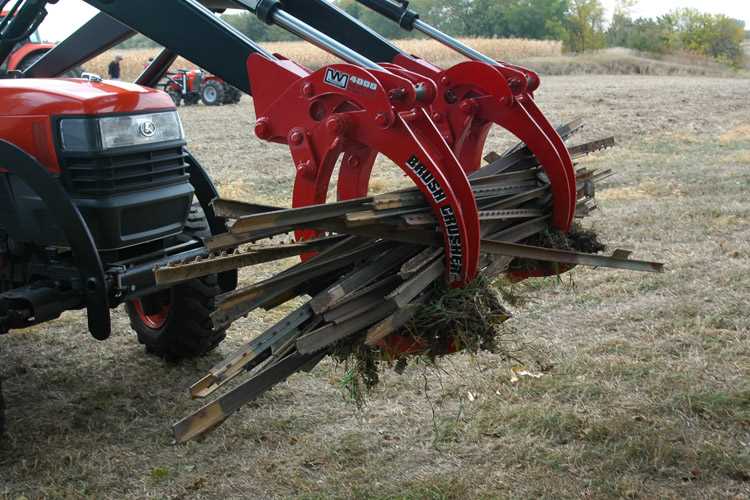
In the realm of agricultural machinery, understanding the essential components that may require substitution is crucial for maintaining efficiency and productivity. This section will explore various frequently replaced elements that contribute to optimal operation and performance.
Hydraulic Cylinders: These components are vital for lifting and lowering implements. Over time, seals may wear out, leading to leaks and diminished functionality. Regular inspection and timely replacement can prevent costly repairs.
Bucket Teeth: The cutting edges of the attachment can wear down due to constant contact with different surfaces. Replacing these teeth ensures effective digging and material handling, improving overall performance.
Hoses and Fittings: Fluid transfer systems are essential for operation. Cracks or damage to hoses can lead to fluid leaks, affecting performance. Regular maintenance and replacements help avoid breakdowns during critical tasks.
Wear Plates: These protective layers safeguard against wear and tear caused by heavy use. Replacing worn wear plates can extend the life of the machinery and enhance its effectiveness.
Filters: Air and hydraulic filters play a critical role in keeping the systems clean. Regular changes are necessary to maintain optimal performance and prevent contaminants from causing damage.
Maintaining awareness of these key components and their potential need for replacement ensures that machinery remains in top condition, enhancing productivity and reducing downtime.
Troubleshooting Hydraulic Leaks

Identifying and resolving fluid leaks in hydraulic systems is crucial for maintaining optimal performance and preventing further damage. These leaks can lead to decreased efficiency and potential operational hazards. This section outlines common causes of leaks and provides practical steps to diagnose and address the issues effectively.
When addressing hydraulic leaks, consider the following potential sources:
- Hoses and Fittings: Inspect for signs of wear, cracks, or loose connections.
- Seals and Gaskets: Check for deterioration or improper seating that may allow fluid to escape.
- Cylinders: Look for leaks around the piston seals, as these are common failure points.
- Reservoirs: Examine for damage or corrosion that could compromise containment.
Follow these steps to troubleshoot effectively:
- Visually inspect all hydraulic components for obvious signs of leakage.
- Clean the area around suspected leaks to identify the source more easily.
- Pressurize the system and observe any areas where fluid is escaping.
- Replace or repair damaged hoses, fittings, seals, or cylinders as necessary.
- Test the system post-repair to ensure all leaks have been addressed.
Regular maintenance and inspections are essential to prevent leaks and ensure the longevity of hydraulic systems. Implementing a proactive approach can help avoid costly repairs and downtime.
Parts Compatibility with Other Models
Understanding the compatibility of components across various machinery can enhance operational efficiency and reduce maintenance costs. By exploring how elements from one model can interchange with those from another, users can make informed decisions when repairing or upgrading their equipment.
Many models share similar designs and specifications, allowing certain components to be utilized interchangeably. This overlap can be particularly beneficial when sourcing replacements, as it expands the options available to owners. Users should carefully check the specifications and dimensions of each element to ensure a proper fit and functionality.
Moreover, manufacturers often provide a list of compatible models in their documentation, aiding users in identifying which items can be effectively used across different machines. Utilizing such resources can save time and money while ensuring optimal performance in various operational settings.