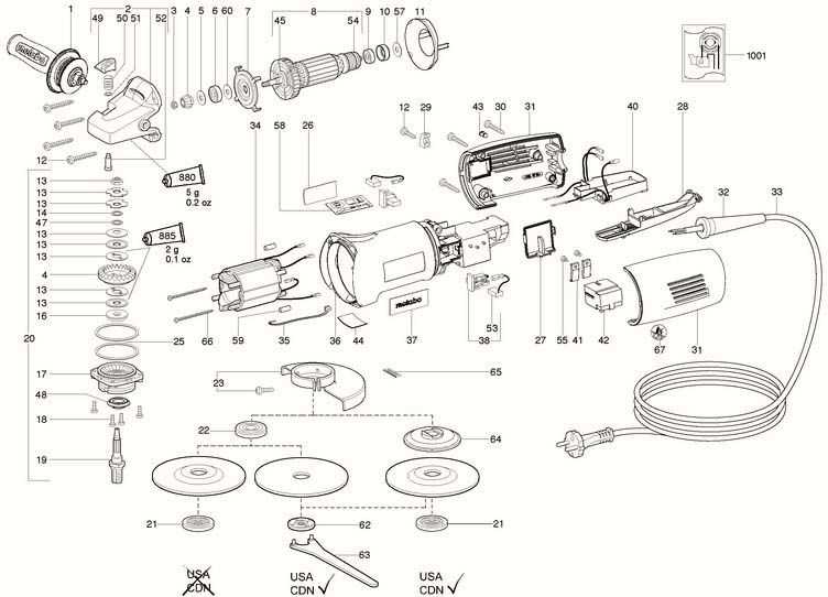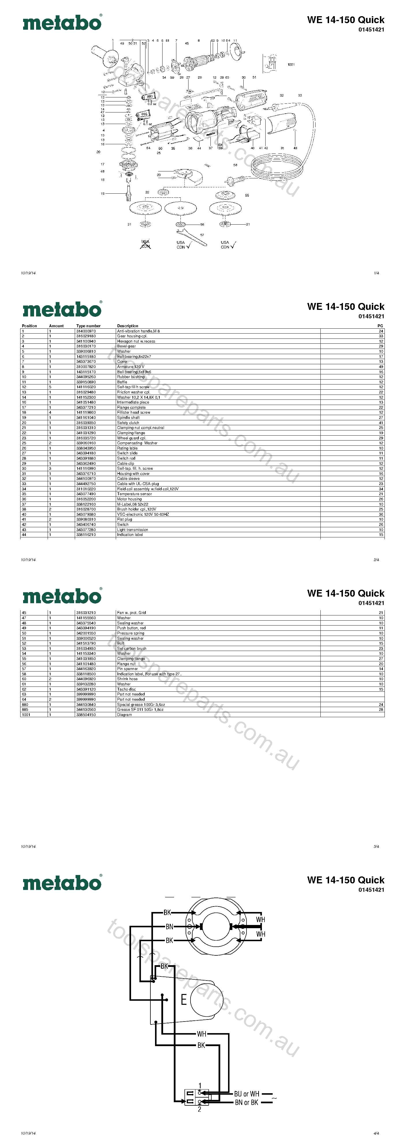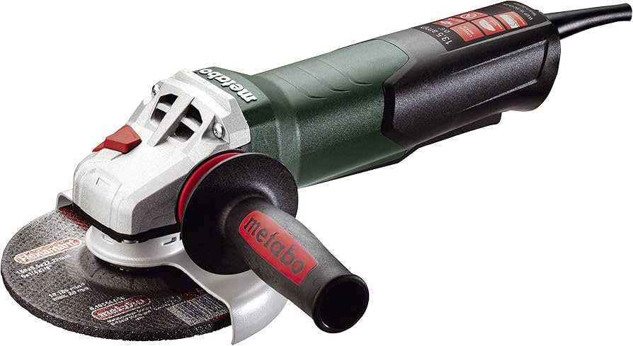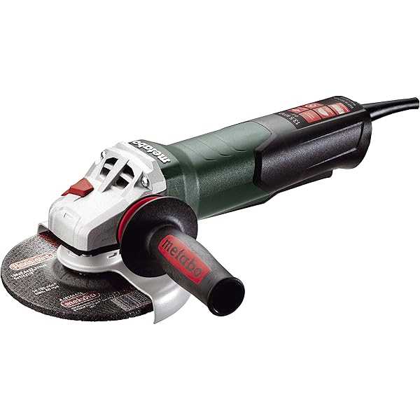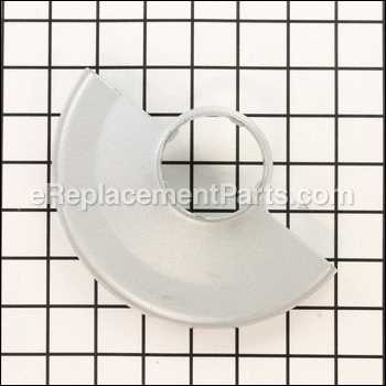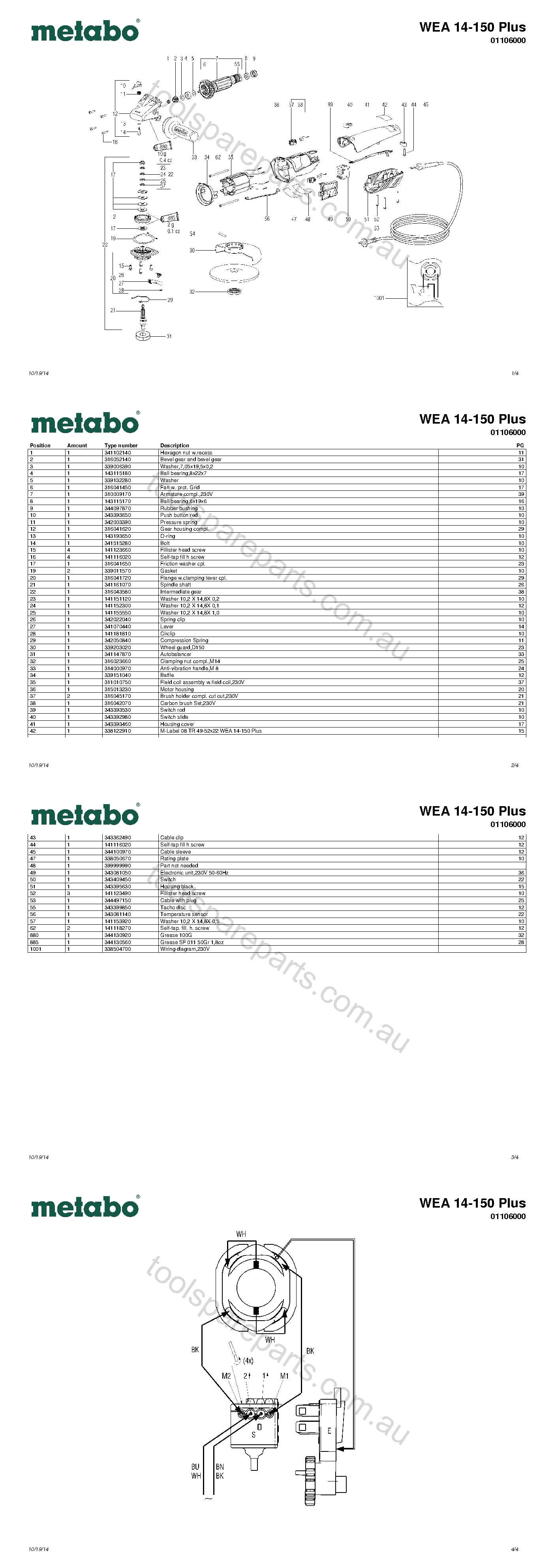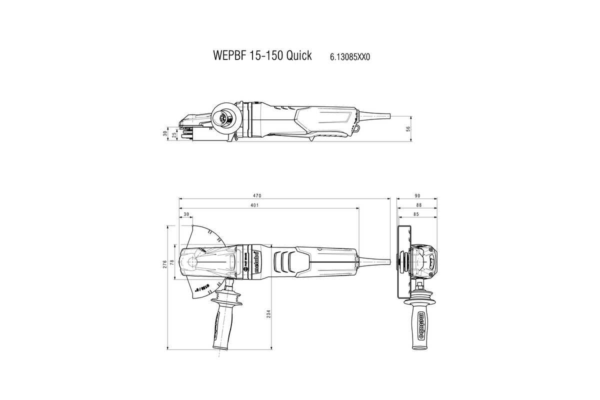
When working with specialized tools, it is essential to have a clear understanding of how each element fits into the overall assembly. Knowing the structure and function of various components allows for efficient maintenance, ensuring that everything operates smoothly. This section provides a detailed exploration of the tool’s layout, helping you navigate its intricate design.
In the following guide, we will take a closer look at the essential elements that make up this power device, focusing on their specific roles and how they interconnect. By familiarizing yourself with the internal setup, you can perform repairs or replacements with confidence, keeping the tool in optimal condition for prolonged use.
Key Components Overview
The machinery is comprised of various essential elements, each designed to perform specific tasks, ensuring optimal operation and longevity. These elements work together harmoniously to provide the power, control, and precision necessary for a wide range of applications.
Motor Unit: This vital part delivers the energy required for all functions, converting electrical input into mechanical power. Its robust construction guarantees long-term performance, even under demanding conditions.
Cutting Mechanism: Precision-engineered, this component is responsible for the machine’s primary function. Its design allows for smooth, efficient cuts across a variety of materials.
Safety Features: Multiple protective elements are integrated to safeguard the user during operation. These features ensure that the machine stops quickly and safely in case of any irregularities.
Ergonomic Design: Attention to user comfort is reflected in the carefully crafted handles and grips, which reduce strain during extended use and allow for better maneuverability.
Exploring Motor Assembly
Understanding the structure of the motor system provides insight into its overall functionality. By dissecting its key components, one can better appreciate how each element contributes to the efficient operation of the entire unit. This section will focus on breaking down the internal mechanisms and how they work together in unison.
Main Components and Their Roles
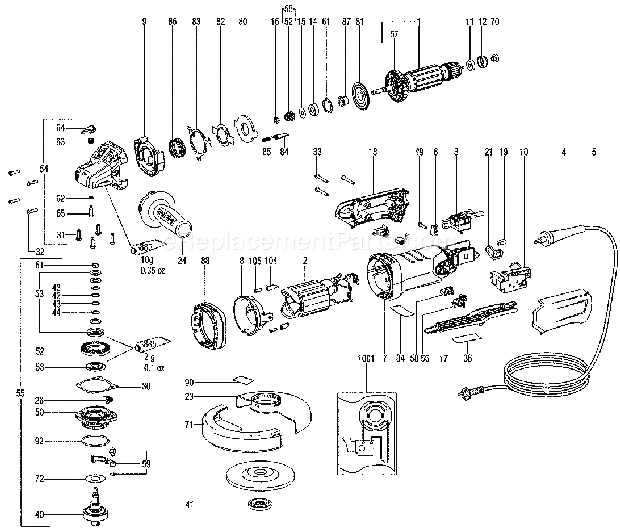
The motor is composed of several critical elements, each serving a specific purpose. From the rotor’s interaction with the stator to the role of the bearings in reducing friction, these components work cohesively to ensure smooth motion. This table outlines the primary parts and their individual functions.
| Component | Function | ||||||||||||||||||||||||||||||||||||||||||
|---|---|---|---|---|---|---|---|---|---|---|---|---|---|---|---|---|---|---|---|---|---|---|---|---|---|---|---|---|---|---|---|---|---|---|---|---|---|---|---|---|---|---|---|
| Rotor | Rotates within the stator to create mechanical energy. | ||||||||||||||||||||||||||||||||||||||||||
| Stator | Provides a stationary magnetic field that drives the rotor’s motion. | ||||||||||||||||||||||||||||||||||||||||||
| Bearings | Reduce friction between moving parts, enabling smoother rotation. | ||||||||||||||||||||||||||||||||||||||||||
| Brushes | Conduct electrical current between stationary
Handle and Grip Design FeaturesThe design of the handle and grip plays a critical role in ensuring comfort and control during extended use. By focusing on ergonomics, manufacturers create tools that reduce fatigue and enhance user precision, allowing for more efficient operation in various environments. Key elements of the grip structure are crafted to provide a balance between firmness and comfort. The textured surface helps maintain a secure hold even in challenging conditions, while the overall shape of the handle is engineered to fit naturally in the hand, improving the overall user experience.
Understanding Ergonomic EnhancementsErgonomic improvements in modern power tools focus on ensuring comfort, efficiency, and safety during prolonged use. These design features aim to reduce fatigue and strain, making the tools more accessible to users with various levels of experience. By refining the balance, grip, and handling, manufacturers provide users with a more seamless and controlled experience, even during the most demanding tasks. The table below outlines the key aspects that contribute to ergonomic improvements and their corresponding benefits for the user:
Cutting Disc Mounting SystemThe process of securely attaching the disc to the machine is a critical aspect of ensuring both the efficiency and safety of the tool in operation. It requires proper alignment and tension, ensuring that the cutting element is firmly held in place without causing imbalance or unnecessary friction. This mechanism must be both robust and user-friendly to facilitate quick adjustments while maintaining high performance during use. Key Components Involved
The system typically consists of a spindle, a flange, and a fastening element. The spindle provides the central axis around which the disc rotates, while the flange holds it steady against the base. A locking nut or lever is used to secure the disc in position. These components work together to ensure that the disc remains stable, even under high-speed conditions. Installation ProcedureAttaching a disc begins with positioning it correctly on the spindle, followed by securing it with the flange. After aligning the disc, the fastening mechanism is engaged, tightening it to a safe and appropriate level. Regular maintenance and inspection of these parts are essential to ensure consistent performance and to prevent potential wear or malfunction during use. Optimizing Disc Replacement EfficiencyEnhancing the process of replacing discs is essential for maintaining performance and productivity. By implementing strategic practices, users can ensure that the transition between discs is seamless and quick, ultimately minimizing downtime and maximizing output. To achieve greater efficiency in disc replacement, consider the following strategies:
By following these recommendations, users can significantly improve the efficiency of the disc replacement procedure, leading to better overall performance and extended lifespan of the equipment. Spindle Lock Mechanism Explained
The spindle lock mechanism is an essential feature in various power tools, providing users with enhanced safety and convenience during operation. This system is designed to secure the spindle in place, allowing for easier and more efficient bit changes while minimizing the risk of accidental movement. Typically, the mechanism operates by engaging a locking device that immobilizes the spindle when activated. This allows the user to replace or adjust attachments without the tool inadvertently rotating. Often, a simple button or lever engages the lock, ensuring a secure fit and promoting safe handling. Understanding this mechanism is crucial for maintaining the longevity of the tool and ensuring optimal performance during use. Moreover, the lock mechanism’s reliability is vital for user confidence. When the spindle is securely locked, users can focus on their tasks without worrying about unexpected tool movements. Regular maintenance and familiarization with the locking system will enhance the overall experience, making tool operation smoother and more productive. Ensuring Safe Operation During UsePrioritizing safety is essential when utilizing any power tool. Proper precautions and awareness can prevent accidents and injuries, ensuring a secure working environment. Understanding the potential risks and implementing best practices can greatly enhance the user experience. Key Safety Practices
Proper Maintenance and Care
Electronic Speed Control UnitThe electronic speed control unit is a critical component that regulates the rotational speed of a motor. By adjusting the power supplied to the motor, it allows for precise control over the tool’s performance. This technology enhances efficiency, improves user experience, and extends the lifespan of the equipment. These units typically employ advanced circuitry to monitor and adjust motor speed based on user input or load conditions. Their design often incorporates features such as overload protection and variable speed settings, enabling a range of applications from delicate tasks to heavy-duty operations.
Incorporating an electronic speed control unit into power tools not only enhances functionality but also improves safety. Understanding its features can aid users in maximizing the capabilities of their equipment while ensuring optimal performance. Balancing Precision and PowerIn the realm of high-performance tools, achieving the perfect equilibrium between accuracy and strength is crucial for effective operation. This balance ensures that users can execute tasks efficiently while maintaining the integrity of their work. By harmonizing these two essential aspects, tools become versatile instruments capable of tackling a wide range of applications. To illustrate this concept, consider the following elements that contribute to the synergy of precision and power:
Ultimately, the fusion of precision and power transforms tools into indispensable allies in various projects. This dynamic not only enhances productivity but also elevates the quality of the results achieved, making it essential for both professionals and enthusiasts alike. Gearbox and Internal StructureThe gearbox and internal components of a power tool play a crucial role in its overall performance and efficiency. Understanding how these elements interact can provide insights into the tool’s functionality, durability, and maintenance needs. Gear MechanismThe gear mechanism is designed to transmit power effectively from the motor to the tool’s output shaft. It consists of various gears that convert rotational movement into the desired torque and speed. This system not only enhances performance but also optimizes energy consumption, ensuring the tool operates smoothly under different conditions. Internal Layout
The internal layout is meticulously engineered to minimize friction and wear, thereby extending the lifespan of the tool. Key components, such as bearings and seals, are strategically placed to support the overall structure and facilitate seamless operation. Regular inspection and maintenance of these internal elements are essential for sustaining peak performance over time. Maximizing Performance Through Gear Design
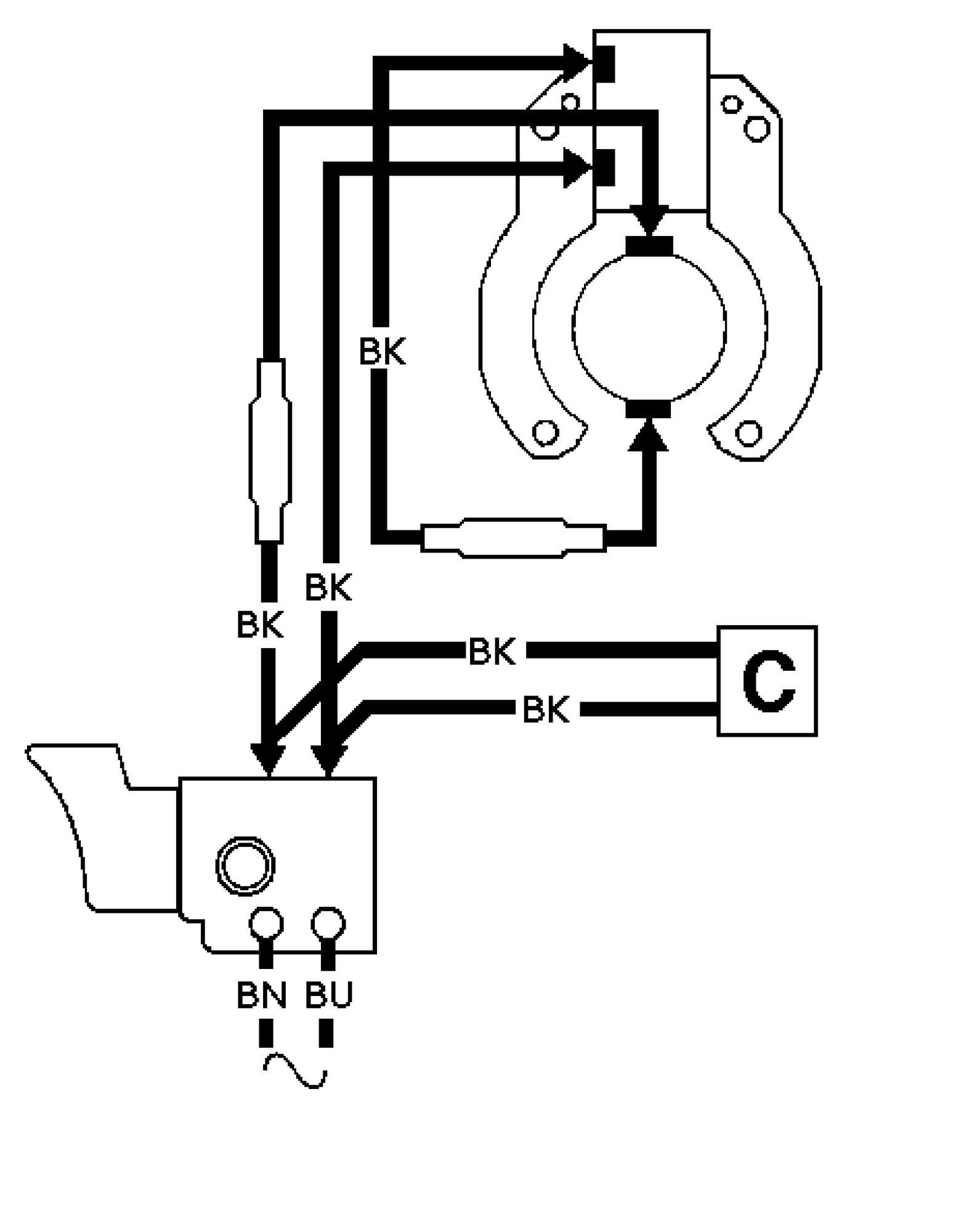
The efficiency of any power tool largely hinges on the intricacies of its gear system. A well-engineered gear assembly can significantly enhance the overall functionality and longevity of the equipment. By focusing on optimal material selection, precise manufacturing techniques, and effective gear ratios, manufacturers can elevate performance and user experience. Key Aspects of Gear ConfigurationUnderstanding the fundamentals of gear mechanics is essential for achieving peak performance. Utilizing high-quality materials not only ensures durability but also minimizes wear and tear. Precision engineering in the gear teeth alignment plays a crucial role in reducing friction and improving energy transfer, thus maximizing efficiency. Impact of Gear Ratios on PerformanceThe selection of appropriate gear ratios is another vital factor. A well-balanced ratio can enhance torque output while maintaining optimal speed. Adjusting these ratios allows users to tailor the tool’s capabilities to specific tasks, leading to improved outcomes and satisfaction. Fine-tuning gear design ultimately leads to a more reliable and powerful tool. Cable and Electrical ConnectionsThe reliability of any power tool largely depends on its wiring and electrical interfaces. Understanding the structure and function of these components is essential for effective maintenance and optimal performance. Proper connections not only enhance functionality but also ensure safety during operation, reducing the risk of malfunctions. Wiring OverviewThe wiring system consists of several key elements that work together to deliver power and control signals. Each component serves a specific purpose, contributing to the overall efficiency of the device. Familiarity with these elements is crucial for troubleshooting and repairs. Connection Table
|
