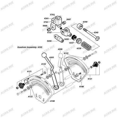
The machinery from Massey Ferguson is known for its reliability and efficiency, serving as a staple for farmers and operators worldwide. Understanding the detailed structure of these machines is essential for proper maintenance and ensuring smooth operation over the long term.
Whether you’re dealing with routine upkeep or tackling more advanced repairs, having a clear visualization of each segment of the equipment can significantly simplify the task. Proper knowledge of its internal organization can help prevent breakdowns and extend the overall lifespan of the machine.
This section will guide you through the key assemblies, offering insights into how different elements of the tractor are interrelated. Equipped with this understanding, you’ll be better prepared to handle everything from minor adjustments to major overhauls.
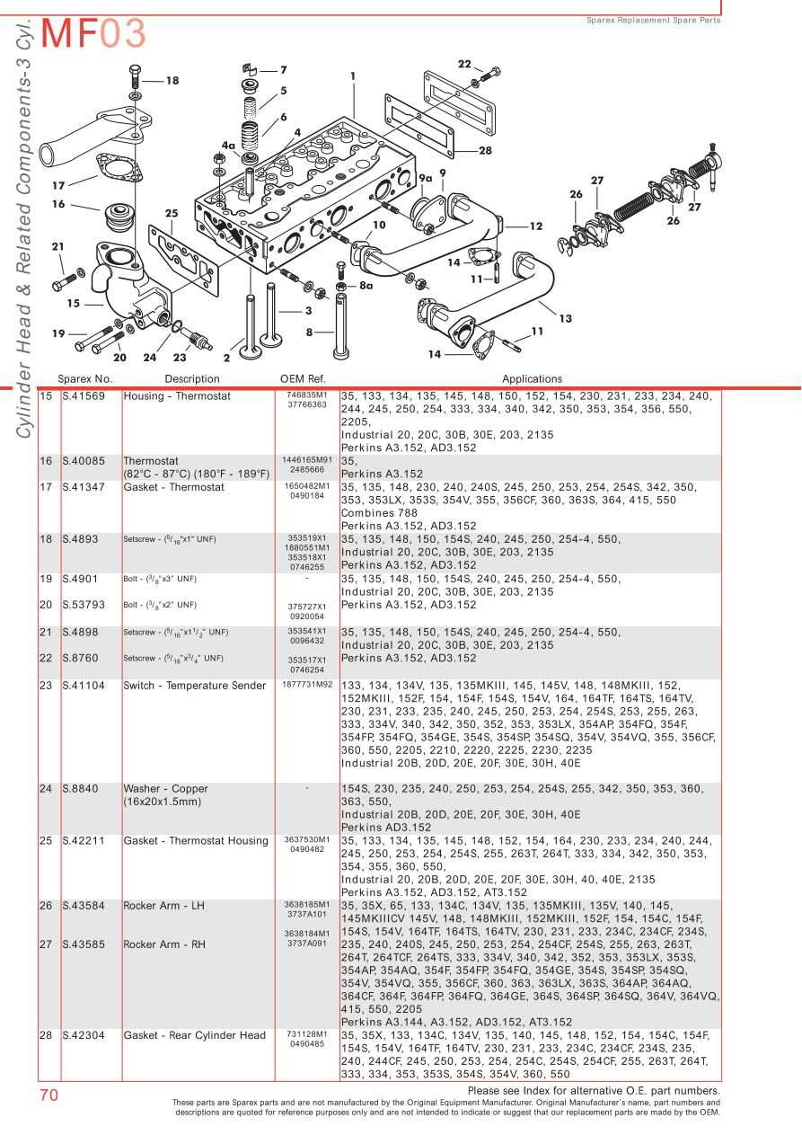
Massey Ferguson 135 Engine Components Overview
The engine in this popular model is designed for reliability and performance, supporting agricultural and mechanical tasks with ease. The configuration of the engine is centered around key elements that ensure smooth operation and durability over time.
- Cylinder Block: This robust part houses the combustion chambers, allowing fuel and air to combine and create the energy needed for operation.
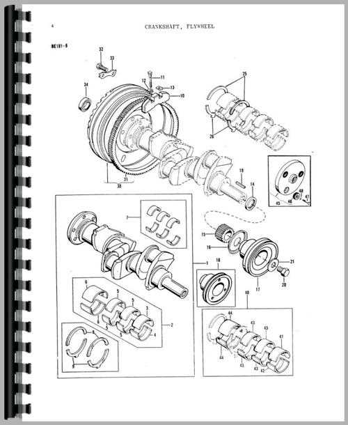
- Crankshaft: Converts the linear motion of the pistons into rotational energy, driving various mechanical components.
- Camshaft: Synchronizes the opening and closing of the engine’s valves, ensuring proper timing for air intake and exhaust.
- Pistons: Move within the cylinder to compress air and fuel, facilitating the combustion process that powers the machine.
- Fuel Injection System: Precisely delivers fuel to the engine for efficient combus
Transmission System Parts Layout
The transmission mechanism plays a crucial role in delivering power from the engine to the wheels, enabling efficient movement and control. It consists of various interconnected components that work in unison to adjust speed, torque, and direction, ensuring smooth operation and reliability in a range of conditions.
Main Components
- Gearbox: The central element responsible for managing different speed ratios.
- Clutch: Engages and disengages the engine from the drivetrain, allowing gear shifts.
- Flywheel: Helps store rotational energy and smooths out engine pulses during operation.
Key Supporting Elements
- Shift Mechanism: Enables the operator to select gears efficiently.
- Driveshaft: Transfers power from the gearbox to the differential.
- Bear
Fuel System Components Breakdown
The fuel system plays a crucial role in delivering the necessary energy for engine operation. Each element within this system is designed to ensure efficient fuel delivery, from the tank to the engine, optimizing performance and reliability. Understanding the key elements of this system can help maintain smooth engine operation and troubleshoot potential issues.
- Fuel Tank: The storage reservoir for fuel, ensuring a steady supply to the engine.
- Fuel Pump: Responsible for moving fuel from the tank through the system, maintaining consistent pressure.
- Fuel Lines: These conduits transport fuel between various components, such as the pump, filter, and injectors.
- Fuel Filter: A critical component that removes impurities from the fuel, preventing engine contamination.
- Injectors: These deliver precise amounts of fuel into the com
Hydraulic System Diagram and Key Parts
The hydraulic mechanism is essential for the efficient operation of various agricultural machinery. It provides the necessary power to raise and lower equipment, ensuring smooth and reliable performance during fieldwork. Understanding the structure and core elements of this system helps in maintaining and troubleshooting any potential issues that may arise during operation.
Main Components of the Hydraulic Assembly
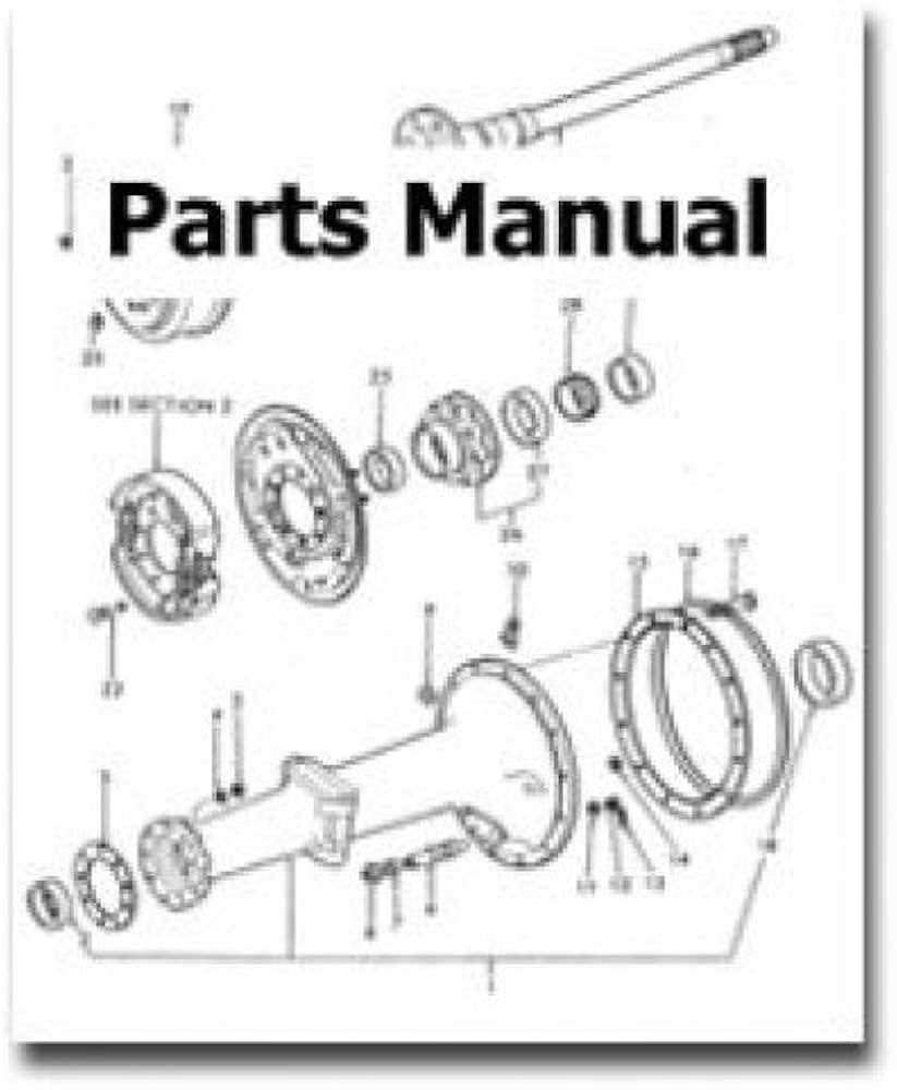
The hydraulic assembly is made up of several interconnected elements that work together to control fluid movement. Each of these components plays a critical role in ensuring the system functions correctly under various load conditions.
Component Function Pump Generates fluid pressure to move attachments. Reservoir Stores hydraulic fluid used throughout the system. Valves Regulate the flow and direction of the hydraulic fluid. Cooling System Parts Structure
The cooling assembly plays a crucial role in maintaining engine temperature stability, ensuring optimal performance during operation. Its efficient design prevents overheating, safeguarding essential components from thermal damage.
The primary elements of the cooling system work together seamlessly to regulate engine temperature, channeling fluid through various pathways. Let’s explore the core components that enable this system to function smoothly.
- Radiator – Acts as the central heat exchanger, where coolant dissipates heat before returning to the engine.
- Water Pump – Drives the flow of coolant throughout the system, circulating it between the engine block and the radiator.
- Thermostat – Regulates the coolant flow based on engine temperature, allowing it to reach optimal working conditions faster.
- Cooling Fan – Provides additional airflow to the radiator, especially when the engine is idling or operating under high temperatures.
- Hoses – These flexible tubes connect the various components, ensuring fluid transfer between the engine, radiator, and water
Electrical System Components Explained
The electrical system of any machinery plays a crucial role in its overall functionality and efficiency. This intricate network consists of various elements that work together to provide power and control for the equipment. Understanding these components is essential for maintenance and troubleshooting, ensuring optimal performance and longevity of the system.
Main Electrical Components
Each element within the electrical framework serves a specific purpose, contributing to the seamless operation of the machinery. From power generation to distribution, the components interact to enable various functions, such as starting the engine and powering auxiliary systems.
Component Function Battery Stores electrical energy to start the engine and power electrical systems. Alternator Generates electricity to recharge the battery and power electrical components while the engine is running. Starter Motor Engages the engine flywheel to start the engine by converting electrical energy into mechanical energy. Fuses Protect circuits by breaking the connection in case of overload or short circuit. Wiring Harness Connects all electrical components, allowing for efficient power distribution and communication. Importance of Maintenance
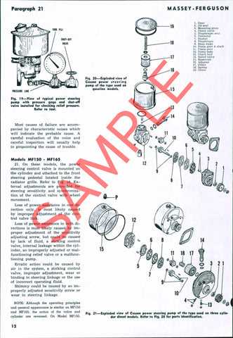
Regular inspection and maintenance of the electrical system components are vital to prevent failures and ensure reliable operation. Identifying issues early can save time and resources, enhancing the overall efficiency of the machinery.
Steering Mechanism Parts Arrangement
The steering mechanism is a crucial component of any vehicle, ensuring precise control and maneuverability. The arrangement of its elements is designed to optimize functionality and enhance driving experience. Understanding how these components interact provides insights into the overall performance of the system.
Key Components
Central to the steering mechanism is the steering wheel, which translates the driver’s inputs into movement. This action is facilitated by a series of linkages and gears that amplify the force applied by the driver. The configuration of these components allows for smooth and responsive handling.
Layout and Functionality
The layout of the steering assembly is engineered to provide stability and ease of use. Each element is strategically positioned to minimize friction and maximize efficiency. Proper alignment is essential for effective operation, ensuring that the vehicle responds accurately to steering commands.
Brake System Components Overview
The braking system is crucial for the safe operation of any machinery, ensuring that vehicles can come to a complete stop when necessary. This system comprises several key elements, each contributing to overall functionality and reliability. Understanding these components helps in maintaining optimal performance and enhances safety during operation.
Key Components
Among the essential elements of the braking system are the brake pads, which create friction against the rotors, allowing the vehicle to decelerate effectively. The hydraulic system plays a vital role, as it transfers force from the brake pedal to the braking mechanism, ensuring responsiveness. Additionally, the master cylinder is responsible for generating the necessary hydraulic pressure to engage the brakes.
Additional Elements
Other significant components include the calipers, which house the brake pads and apply pressure to the rotors. The brake lines are essential for carrying the hydraulic fluid throughout the system, facilitating smooth operation. Regular inspection and maintenance of these elements are imperative for ensuring the braking system’s efficiency and longevity.
Front Axle Parts and Diagram
The front axle assembly is a crucial component that plays a significant role in the overall functionality and performance of a vehicle. It supports the weight of the front end, enables steering, and facilitates the transfer of power from the engine to the wheels. Understanding the individual components and their arrangement is essential for maintenance and repairs.
Key elements of the front axle assembly include the spindles, which connect the wheels to the axle, and the hubs, responsible for allowing wheel rotation. Additionally, the bearings ensure smooth movement and reduce friction between moving parts. The kingpins play a vital role in the steering mechanism, allowing the wheels to pivot effectively. Other notable components are the steering knuckles and axle shafts, which contribute to the overall strength and durability of the assembly.
To maintain optimal performance, regular inspections and servicing of these components are recommended. This ensures that any wear or damage is addressed promptly, preserving the vehicle’s handling and stability.
Rear Axle Assembly Parts Breakdown
The rear axle assembly plays a crucial role in the overall functionality of agricultural machinery. It serves as a vital component that connects the wheels to the vehicle’s frame, ensuring stability and efficient power transfer during operation. Understanding the various elements within this assembly can aid in maintenance and troubleshooting, ultimately enhancing performance and longevity.
Key components involved in the rear axle assembly include:
- Axle Housing: The main structure that encases the axle shaft and supports the differential.
- Differential: A mechanism that allows the wheels to rotate at different speeds, especially during turns.
- Axle Shafts: Rods that transmit power from the differential to the wheels.
- Wheel Hubs: Connect the axle shafts to the wheels and provide mounting points for the tires.
- Bearings: Components that reduce friction between moving parts, ensuring smooth rotation.
- Seals: Prevent dirt and moisture from entering the assembly, protecting internal components.
Regular inspection and maintenance of these elements are essential for optimal performance and to prevent costly repairs in the future. Understanding the layout and functionality of each component enables operators to identify issues early and maintain their equipment effectively.
Exhaust System Key Components
The exhaust system of a vehicle plays a crucial role in ensuring optimal performance and emissions control. It consists of several essential elements that work together to direct exhaust gases away from the engine, reduce noise, and minimize harmful pollutants. Understanding these components is vital for maintaining the efficiency and functionality of the system.
Exhaust Manifold
The exhaust manifold serves as the initial point of the exhaust flow. It collects gases from the engine’s cylinders and channels them into the exhaust system. A well-designed manifold improves engine efficiency and enhances overall performance by ensuring that exhaust gases are expelled swiftly and efficiently.
Muffler
The muffler is responsible for reducing the noise produced by the engine’s exhaust gases. It employs various chambers and baffles to dissipate sound waves, ensuring a quieter operation. Additionally, mufflers can impact the flow of exhaust gases, influencing engine performance and efficiency.
Clutch System Parts and Functions
The clutch system plays a vital role in the operation of machinery, enabling the transfer of power from the engine to the transmission. This essential mechanism allows for smooth gear changes and efficient vehicle control. Understanding the various components and their specific functions helps in maintaining optimal performance and ensuring longevity.
Key Components of the Clutch System
- Clutch Disc: A friction component that engages and disengages the engine power from the transmission.
- Pressure Plate: A device that applies pressure to the clutch disc, holding it against the flywheel.
- Flywheel: A rotating disc that provides a surface for the clutch disc to press against and helps maintain engine momentum.
- Release Bearing: Facilitates the disengagement of the clutch by pressing against the pressure plate when the pedal is depressed.
- Clutch Fork: A lever mechanism that connects the release bearing to the clutch pedal, allowing for smooth engagement and disengagement.
Functions of Each Component
- Clutch Disc: When engaged, it connects the engine’s flywheel to the transmission, allowing for power transfer. When disengaged, it separates these two components, interrupting the power flow.
- Pressure Plate: Ensures that the clutch disc remains pressed against the flywheel when engaged, providing the necessary friction for power transfer.
- Flywheel: Stores kinetic energy and helps in the smooth operation of the engine by maintaining momentum during power interruptions.
- Release Bearing: Engages the pressure plate to release the clutch disc, facilitating gear shifts.
- Clutch Fork: Transmits the force from the clutch pedal to the release bearing, enabling the driver to engage or disengage the clutch efficiently.