When maintaining or repairing any mechanical system, having a clear overview of its internal structure is essential. Understanding how various elements fit together allows for more efficient troubleshooting and ensures proper upkeep. Whether you’re a seasoned technician or a beginner, familiarity with the core layout is the foundation for effective work.
Breaking down the assembly of such systems reveals the critical relationships between the individual elements. Recognizing these connections not only aids in identifying issues but also enhances your ability to perform repairs with confidence. Visualizing the framework can significantly improve both accuracy and efficiency during any mechanical task.
Furthermore, knowing the intricate details of each component helps you ensure that replacements and repairs are done correctly. Each part has a specific role within the overall structure, and a thorough understanding can prevent common mistakes and enhance the longevity of the system.
Component Layout Overview
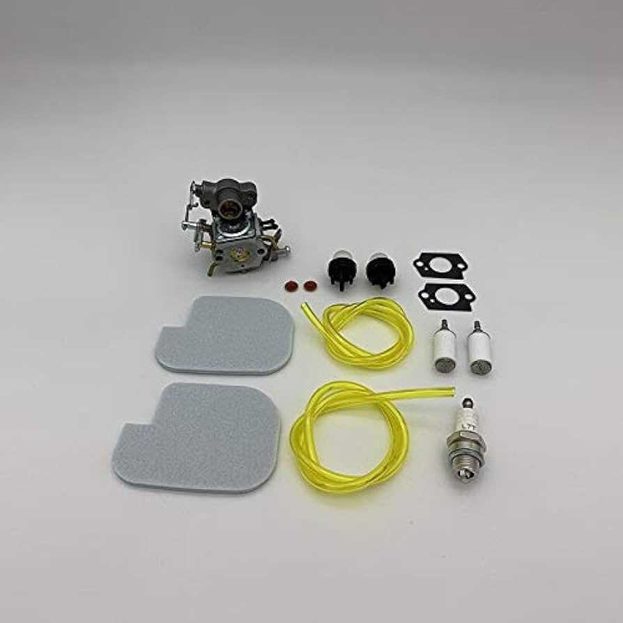
The following section provides a comprehensive look into the structural arrangement of various elements in this model. Each essential piece is strategically positioned to ensure proper functionality and seamless operation. Understanding how these elements are interconnected helps to grasp the inner workings of the system as a whole.
Main Assembly Structure
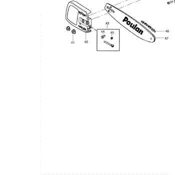
The central assembly is comprised of several key elements that are meticulously organized to optimize performance. Each section plays a crucial role in maintaining the overall balance and ensuring that every component functions in harmony.
Detailed Breakdown of Key Elements
In this overview, individual components are examined in terms of their placement and relationship with surrounding parts. This helps to identify any critical areas where adjustments might be necessary for better efficiency. Ensuring all elements
Engine Components Breakdown
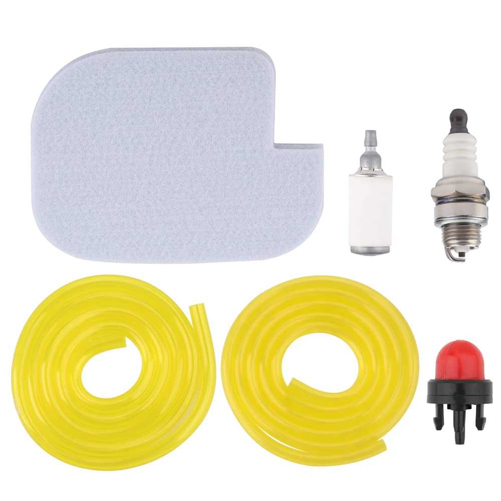
Understanding the key elements of an engine is essential for ensuring proper maintenance and operation. Each section of the motor plays a crucial role in delivering power and efficiency, contributing to the overall functionality and durability of the machinery.
Core Components
The engine consists of several primary elements that are critical to its operation. These include the cylinder, crankshaft, piston, and connecting rod. Each of these parts works together to convert fuel into mechanical energy, ensuring smooth engine performance.
Ignition and Fuel Systems
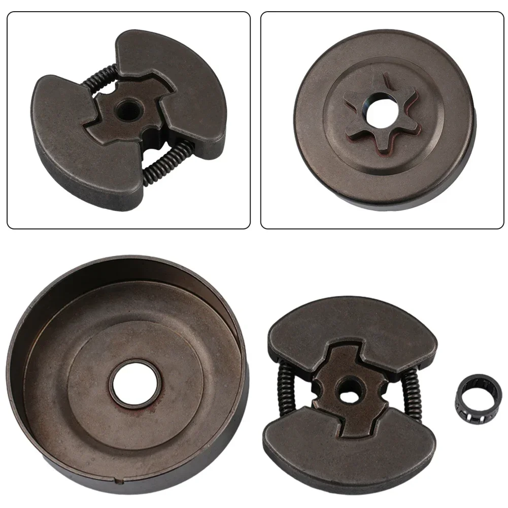
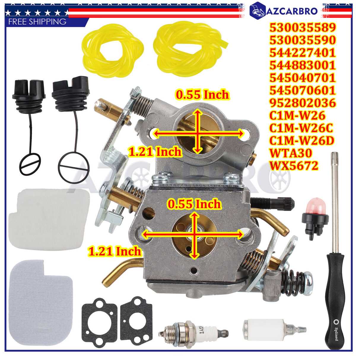
The ignition system is responsible for starting the engine, while the fuel system delivers the necessary fuel mixture to keep it running. Spark plugs, carburetors, and fuel injectors are some of the key elements involved in this process, ensuring efficient combustion.
Fuel System Layout
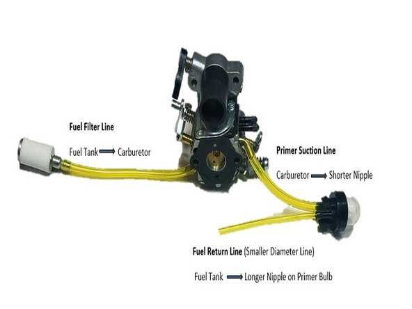
The fuel system is designed to deliver the necessary fuel to the engine with optimal efficiency. Each component plays a critical role in ensuring that fuel is properly routed from the tank to the engine for combustion. Understanding the key elements and their connections helps in maintaining and troubleshooting the system.
| Component | Function | ||||||||||||||||||||||||||||||||||||||||||||||
|---|---|---|---|---|---|---|---|---|---|---|---|---|---|---|---|---|---|---|---|---|---|---|---|---|---|---|---|---|---|---|---|---|---|---|---|---|---|---|---|---|---|---|---|---|---|---|---|
| Fuel Tank | Stores the fuel and serves as the starting point for its journey through the system. | ||||||||||||||||||||||||||||||||||||||||||||||
| Fuel Lines | Transport fuel from the tank to various parts of the system, maintaining pressure and flow. | ||||||||||||||||||||||||||||||||||||||||||||||
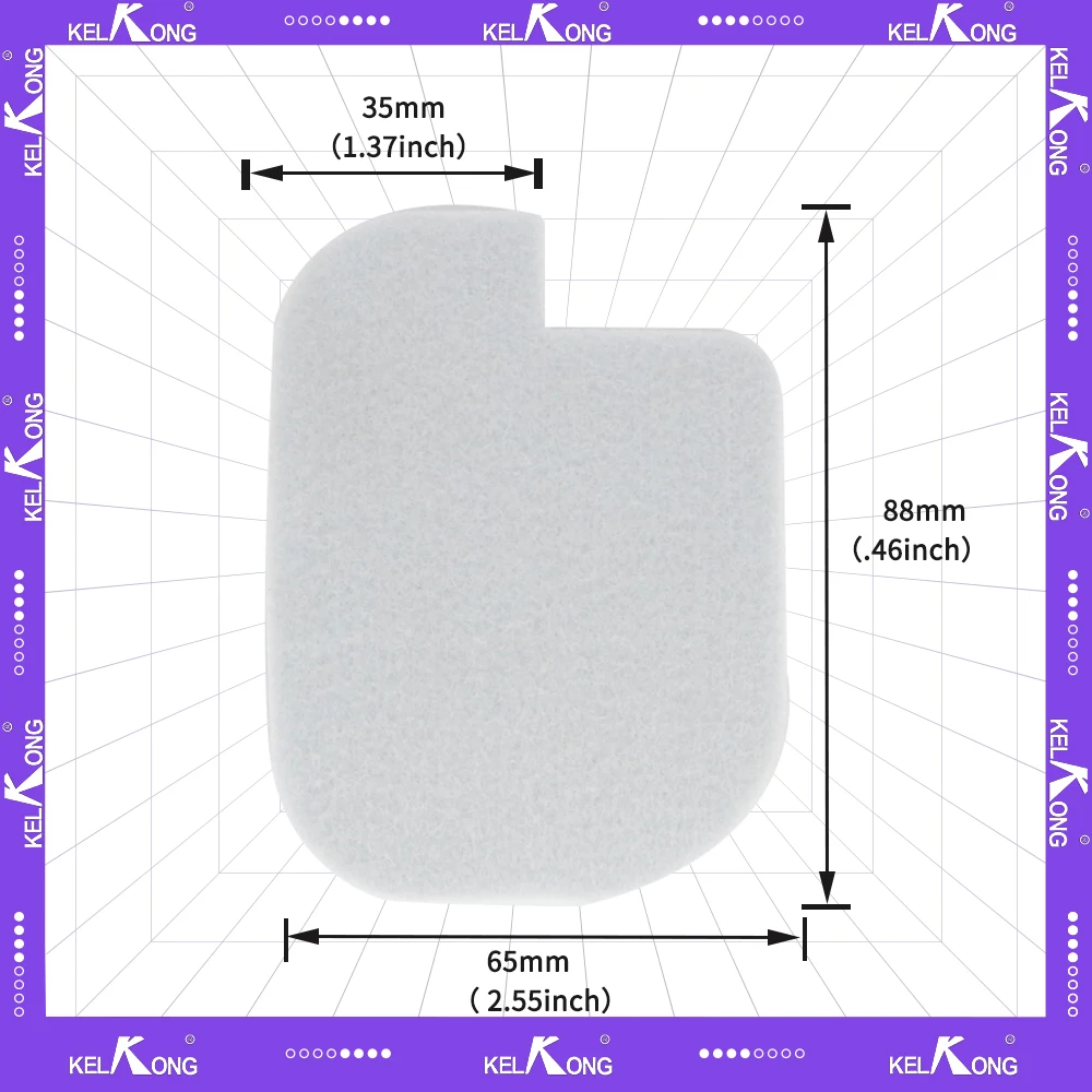
| Fuel Filter | Removes impurities from the fuel before it reaches the engine, ensuring a clean combustion process. | ||||||||||||||||||||||||||||||||||||||||||||||
| Carburetor |
Ignition Parts and Wiring
The ignition system plays a crucial role in ensuring the engine operates efficiently by managing the spark needed to ignite the fuel. Properly maintaining and understanding this system is essential for reliable operation. The components involved in this process work together to provide a consistent and powerful ignition spark, ensuring smooth engine performance. Key Components of the Ignition SystemThe ignition setup typically includes several elements that work in unison to create and deliver the spark. These elements include the ignition coil, spark plug, and the wiring that connects them. The coil transforms the battery’s voltage into a higher voltage, which is then sent to the spark plug through high-tension wires. Wiring Configuration and ConnectivityThe wiring in the ignition system is designed to ensure efficient transmission of electrical current. Proper insulation and secure connections between components are vital to prevent voltage leaks and maintain a stable spark. Regular inspection of the wiring and connectors is recommended to avoid electrical issues.
By regularly inspecting and maintaining these components, users can ensure that the cutting tool operates efficiently and effectively. Proper understanding of the chain and guide bar assembly contributes significantly to the longevity and reliability of the equipment. Starter Mechanism Components
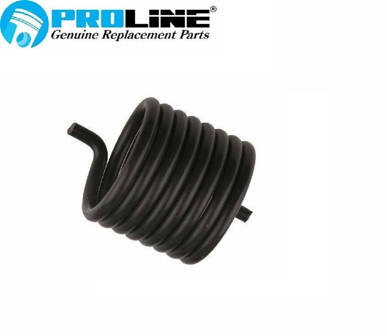
The starter mechanism is a crucial system within an engine, designed to initiate the combustion process by providing the necessary torque to the engine’s flywheel. This mechanism consists of several key elements that work together to ensure reliable and efficient engine start-up. Understanding the components involved can help in diagnosing issues and performing maintenance effectively. Key Elements of the Starter Mechanism
Additional Components
Each component plays a vital role in the successful operation of the starter mechanism, and understanding their functions can aid in troubleshooting and repairs. Clutch and Drive System Parts
The clutch and drive mechanism are crucial components in ensuring smooth transmission of power from the engine to the wheels. This system is designed to facilitate the engagement and disengagement of the engine’s torque, allowing for effective vehicle operation under various conditions. Understanding the different elements involved in this assembly is essential for maintenance and repair.
Oil Pump and Lubrication PathThe oil pump plays a crucial role in ensuring the efficient operation of an engine by facilitating the movement of lubricating fluid throughout its various components. This mechanism is essential for reducing friction, minimizing wear, and maintaining optimal temperatures during engine operation. Understanding the flow of lubrication can greatly enhance the performance and longevity of the engine. Functionality of the Oil Pump
The primary function of the oil pump is to circulate the lubricant from the sump to critical engine parts. This process not only lubricates moving components but also helps to remove heat generated during combustion. The pump operates under varying pressure conditions, which are influenced by engine speed and temperature. Lubrication Path OverviewIn an effective lubrication system, the oil travels through a network of channels and galleries, reaching vital areas such as bearings, pistons, and camshafts. As the lubricant flows, it forms a protective film on surfaces, preventing direct metal-to-metal contact. This pathway is designed to ensure that the lubricant reaches all necessary components quickly and efficiently. Protective Casing and Frame DesignThe design of protective enclosures and structural frameworks is crucial for ensuring the durability and reliability of electronic devices. These elements serve not only as barriers against environmental factors but also contribute to the overall aesthetic and functionality of the product. A well-engineered casing enhances performance by providing stability and safeguarding internal components from physical damage. Material SelectionChoosing the right materials for the casing and frame is essential to balance weight, strength, and cost. Common materials include:
Design ConsiderationsEffective design must take into account factors such as impact resistance, heat dissipation, and ease of assembly. Integrating features like ventilation openings and shock-absorbing elements can enhance protection while maintaining device performance. Additionally, aesthetic considerations should not be overlooked, as the visual appeal can significantly influence user perception and marketability. |
