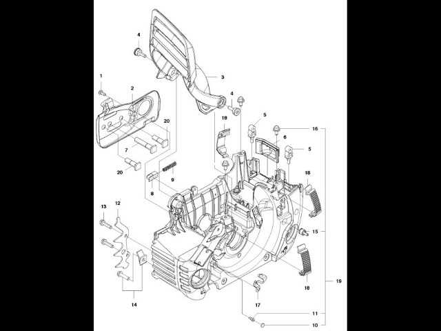
The effective functioning of any machinery relies heavily on the intricate arrangement of its individual elements. A comprehensive overview of how these elements interact can significantly enhance one’s ability to diagnose issues and perform maintenance. In this section, we will explore the intricacies of a specific model’s configuration, shedding light on the relationships between various components.
By delving into the specifics of this model’s assembly, users will gain insights into the optimal functioning of each segment. Recognizing how these components fit together not only aids in troubleshooting but also facilitates efficient repairs and upgrades. This understanding empowers users to handle their equipment with greater confidence and precision.
Moreover, familiarizing oneself with the layout can be instrumental when seeking replacement elements or modifications. This knowledge streamlines the process of identifying compatible parts, ensuring that any enhancements or repairs are executed effectively. A clear grasp of the arrangement ultimately leads to improved performance and longevity of the machinery.
Essential Parts of P4018wt Model
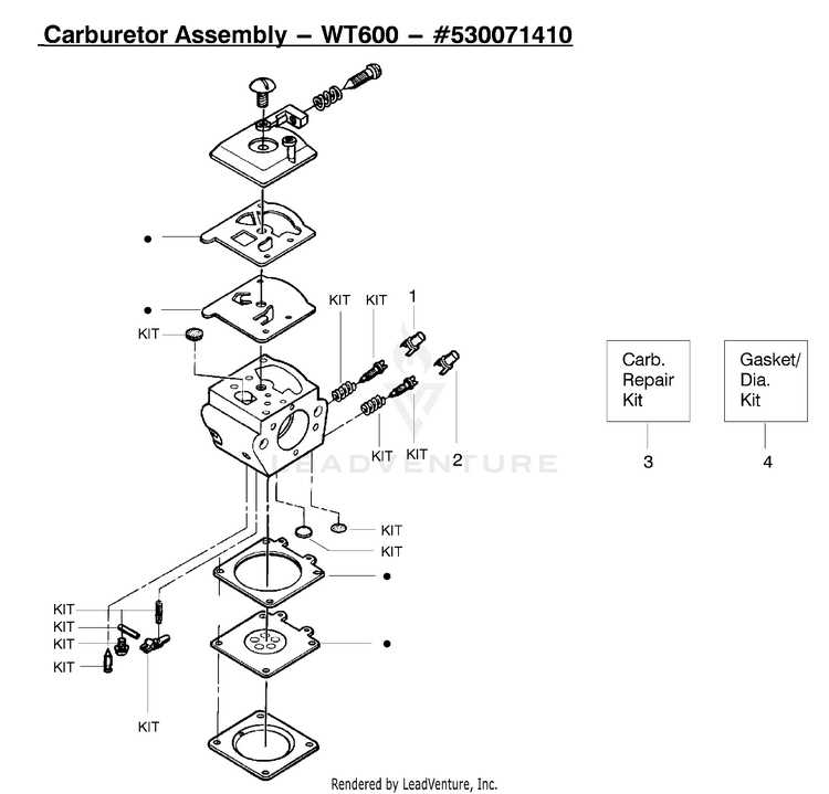
This section provides an overview of the critical components that contribute to the functionality and efficiency of the specified model. Understanding these elements is crucial for anyone looking to optimize performance or perform maintenance tasks.
Key Components
- Main Housing: This structure provides the necessary support and protection for internal elements.
- Power Supply: Vital for ensuring that the unit operates smoothly and efficiently.
- Control Panel: Offers user interfaces to manage various functions easily.
- Cooling System: Essential for maintaining optimal temperature during operation.
- Connecting Ports: Facilitate interaction with other devices and systems.
Functional Elements

- Drive Mechanism: Responsible for the movement and operation of internal processes.
- Safety Features: Integrated to prevent potential hazards and ensure user protection.
- Monitoring Sensors: Provide real-time feedback on operational status and efficiency.
- Maintenance Access: Designed to allow easy reach for servicing and repairs.
Visual Representation of Internal Elements
This section provides an insightful overview of the internal components of the device, illustrating how each part contributes to its overall functionality. Understanding the arrangement and relationship of these components is essential for effective maintenance and troubleshooting.
Key Components Overview
Each element plays a crucial role in the performance and efficiency of the unit. Below is a detailed table highlighting the significant components, their functions, and their corresponding positions within the system.
| Component Name | Function | Location |
|---|---|---|
| Power Supply Module | Provides electrical energy to the device. | Located at the rear section. |
| Main Control Board | Processes all operational commands and controls functions. | Central position within the housing. |
| Cooling Fan | Maintains optimal operating temperature. | Adjacent to the power supply module. |
| Input/Output Ports | Facilitates connections to external devices. | Located on the front panel. |
Conclusion
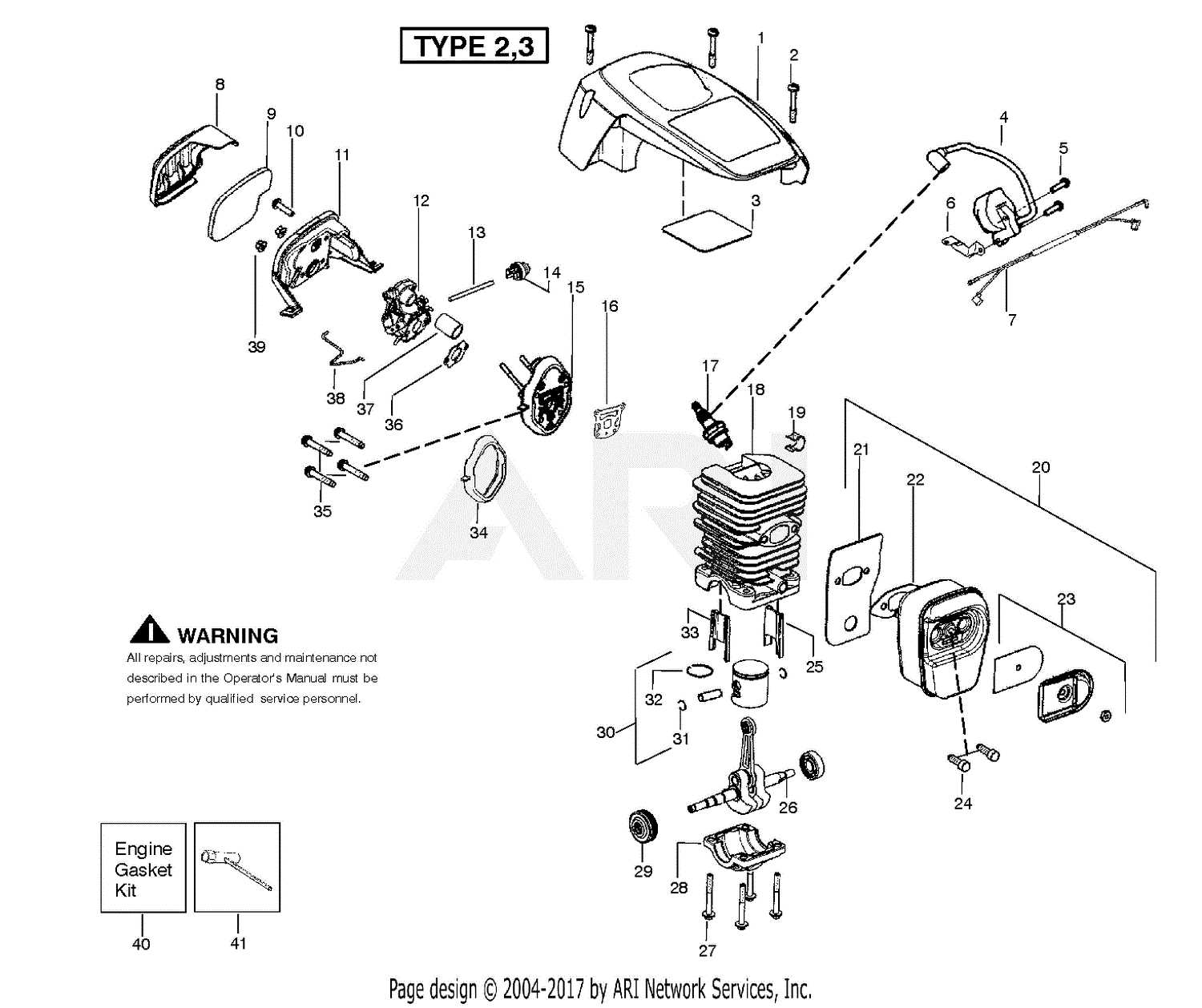
Recognizing the arrangement of these crucial elements is vital for effective diagnostics and repair. This visual representation aids in understanding the intricate relationships between various components, ultimately enhancing the user’s experience.
Functionality of Each Component Explained
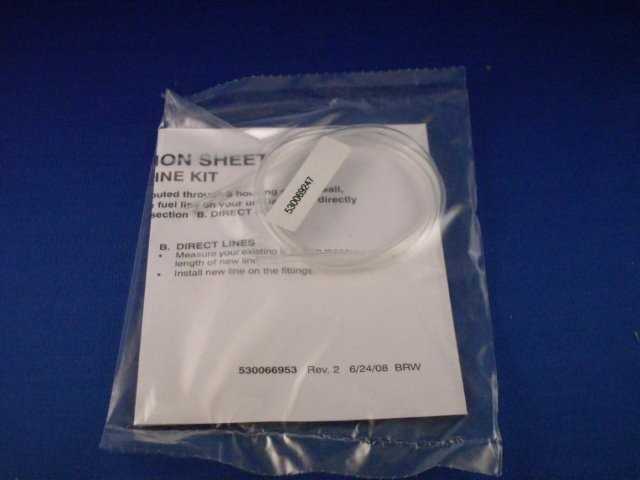
This section delves into the roles and purposes of the various elements within the assembly, providing insight into how each piece contributes to the overall operation. Understanding these functions is crucial for maintenance and effective usage.
Each element serves a specific role, whether it be facilitating movement, supporting structural integrity, or ensuring efficient energy transfer. The combination of these components works harmoniously to achieve optimal performance, allowing for smooth operation and enhancing user experience.
Furthermore, recognizing the interaction between individual parts can aid in troubleshooting and repairs. By understanding how one component influences another, users can make informed decisions when addressing issues, ultimately prolonging the lifespan of the entire system.
Assembly Instructions for P4018wt Parts
This section provides essential guidance for the proper assembly of components associated with the specified model. Following these instructions will ensure that each element is correctly integrated, enhancing overall functionality and performance.
Before starting the assembly process, ensure all necessary tools are available. Organize all components for easy access, and review the following table to familiarize yourself with each element’s designation and purpose.
| Component Name | Function | ||||||||||||
|---|---|---|---|---|---|---|---|---|---|---|---|---|---|
| Base Frame | Provides stability and support for the assembly. | ||||||||||||
| Control Panel | Facilitates user interaction and functionality control. | ||||||||||||
| Power Supply Unit | Delivers energy required for operation. | ||||||||||||
| Connecting Rods | Links various components, ensuring coordinated movement. |
| Component Type | Description | Source |
|---|---|---|
| OEM Components | Original parts provided by the manufacturer, ensuring compatibility and quality. | Manufacturer’s website, authorized dealers |
| Aftermarket Components | Third-party alternatives that may offer similar quality at a reduced price. | Online retailers, local shops |
| Refurbished Components | Previously used parts that have been restored to a functional state. | Specialized refurbishing companies |
Considerations for Selection
Choosing the right component for your machinery involves assessing several factors. It is essential to consider compatibility, warranty options, and overall reliability. Doing thorough research on suppliers and reading reviews can provide valuable insights into the performance and durability of different offerings.
Tools Required for Component Handling
When working with various elements in a mechanical or electronic setup, having the right instruments is crucial for efficient assembly and maintenance. These essential tools ensure precision and help avoid damage to sensitive components, making the handling process smoother and more effective.
Essential Instruments
- Screwdrivers: A variety of screwdrivers, including Phillips and flathead, are necessary for fastening or removing screws.
- Plier Sets: Needle-nose and slip-joint pliers assist in gripping and manipulating parts securely.
- Wrenches: Adjustable and socket wrenches are vital for tightening or loosening nuts and bolts.
- Cutting Tools: Wire cutters and utility knives are useful for trimming and preparing wires or other materials.
- Measuring Devices: Calipers and rulers help ensure accurate measurements of components.
Safety Equipment
- Safety Glasses: Protect your eyes from debris and accidental splashes while working.
- Gloves: Wearing appropriate gloves can prevent cuts and ensure a better grip on tools.
- Dust Masks: When handling materials that generate dust, masks can protect respiratory health.
Compatibility with Other Models
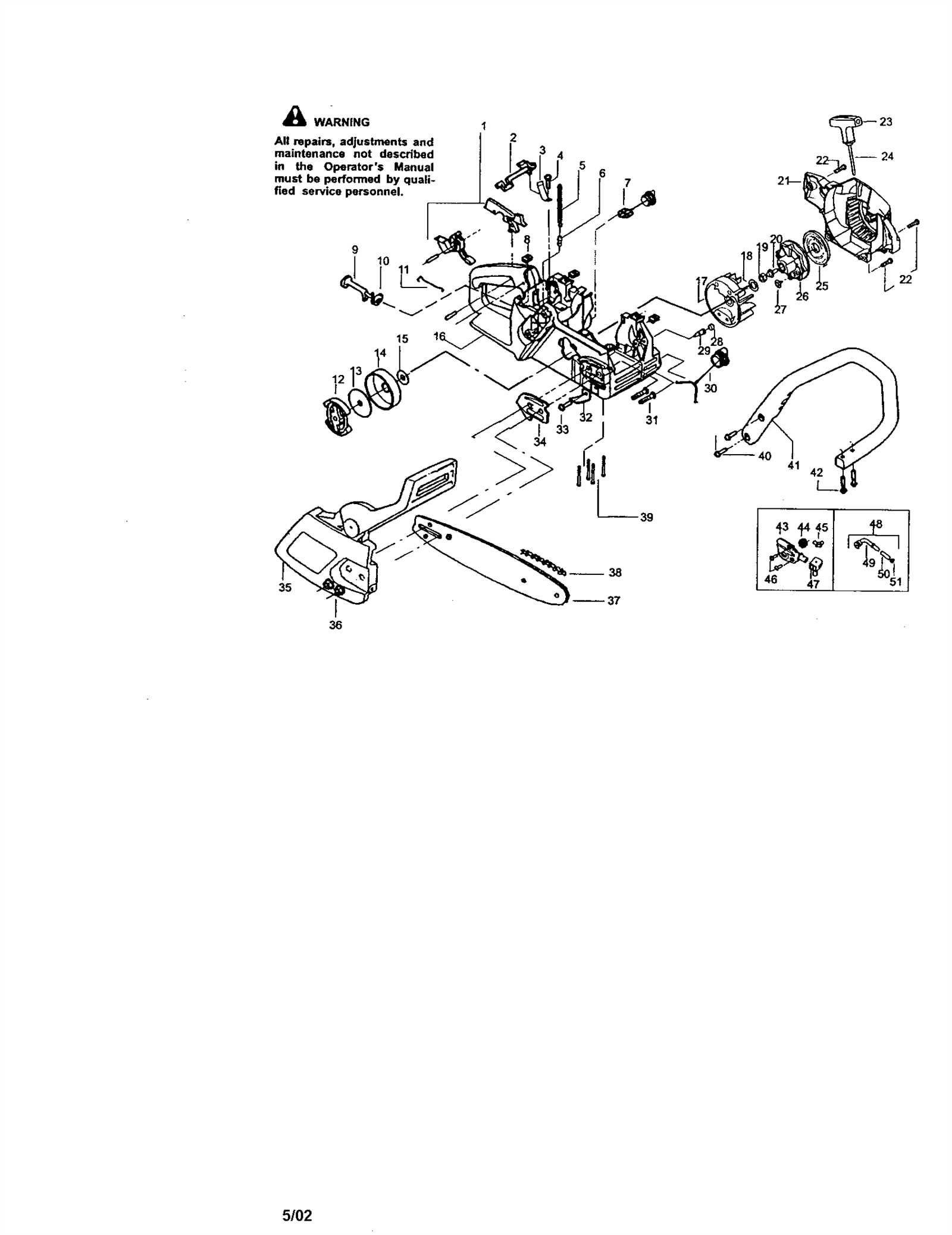
This section explores the interrelations and adaptability of various units within a specific range. Understanding how different models align can enhance functionality and streamline maintenance processes, ensuring users can make informed decisions when replacing components or upgrading their systems.
Similar Units
Several devices share similarities in structure and operation, allowing for interchangeable elements. By identifying these compatible units, users can easily locate alternatives when seeking replacements. This adaptability not only increases the longevity of devices but also reduces downtime during repairs.
Limitations and Considerations
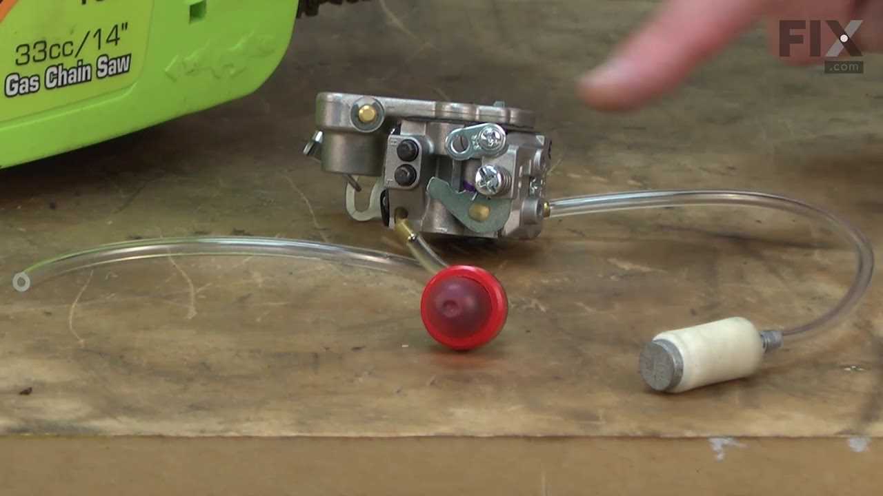
While compatibility can be beneficial, it is essential to be aware of potential limitations. Certain models may require specific adjustments or may not support all features of the alternative components. Thorough research is advised to ensure optimal performance and avoid issues related to mismatched specifications.
FAQs about P4018wt Parts Diagram
This section addresses common inquiries related to the visual representation of components associated with a specific model. Understanding these elements can help users identify the necessary pieces for repairs or upgrades.
- What is the purpose of this visual guide?
The visual guide serves as a reference for users to locate and understand the various components needed for maintenance or replacement. It simplifies the process of identifying each element’s position and function.
- How can I use this guide effectively?
To use the guide effectively, refer to the labeled sections when searching for specific components. Cross-reference the numbers or codes with your model’s specifications to ensure accuracy.
- Where can I find replacement components?
Replacement elements can typically be found through authorized dealers, online marketplaces, or specialty stores. Always verify compatibility with your model before purchasing.
- Are there any tips for installation?
When installing new components, follow these guidelines:
- Ensure the power supply is disconnected before beginning any work.
- Use appropriate tools to prevent damage to the components.
- Refer to the visual guide for proper placement and orientation.
- What should I do if I can’t find a specific component?
If you are unable to locate a specific element, consider reaching out to customer support for assistance. They can provide guidance on alternative solutions or compatible components.

