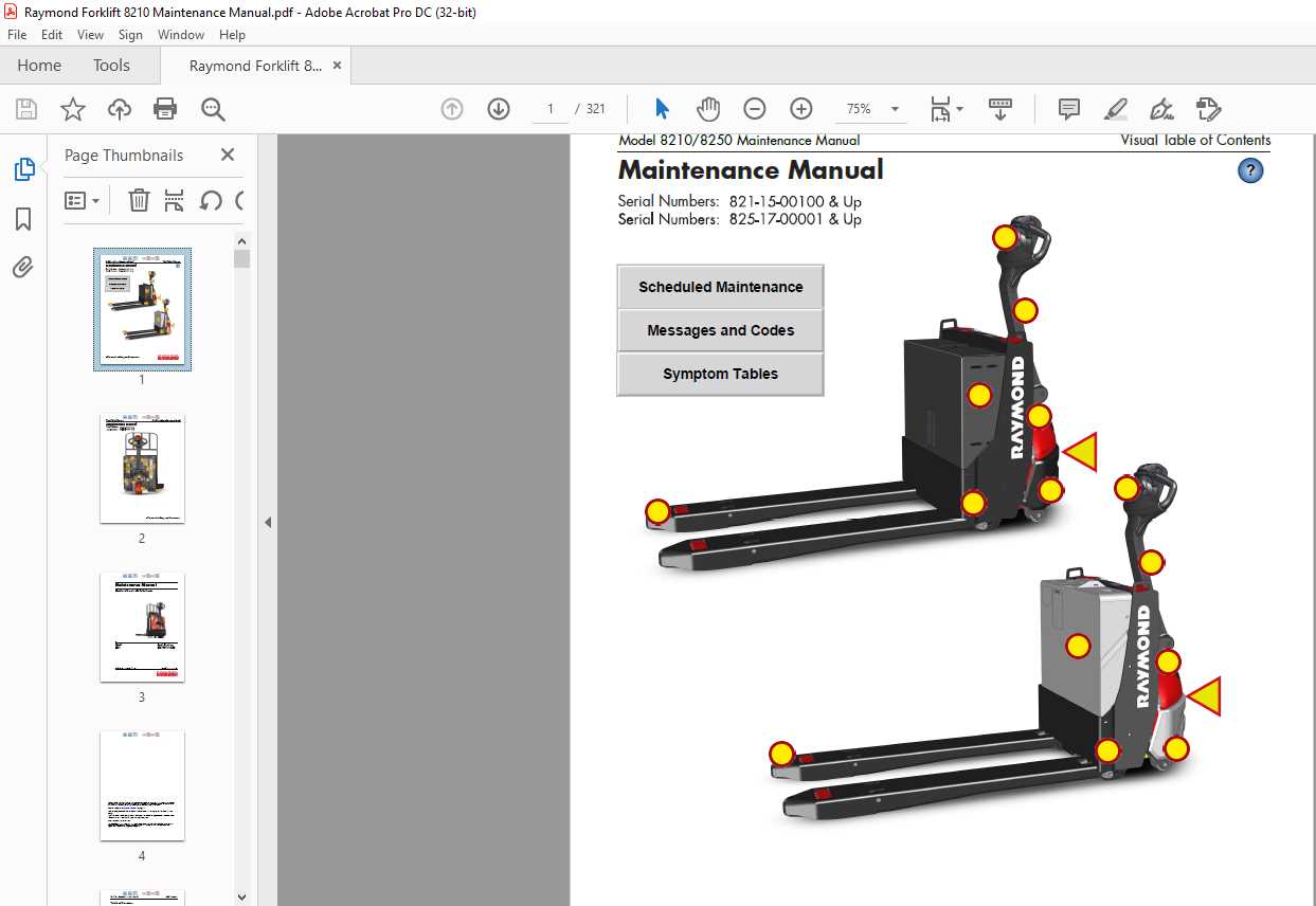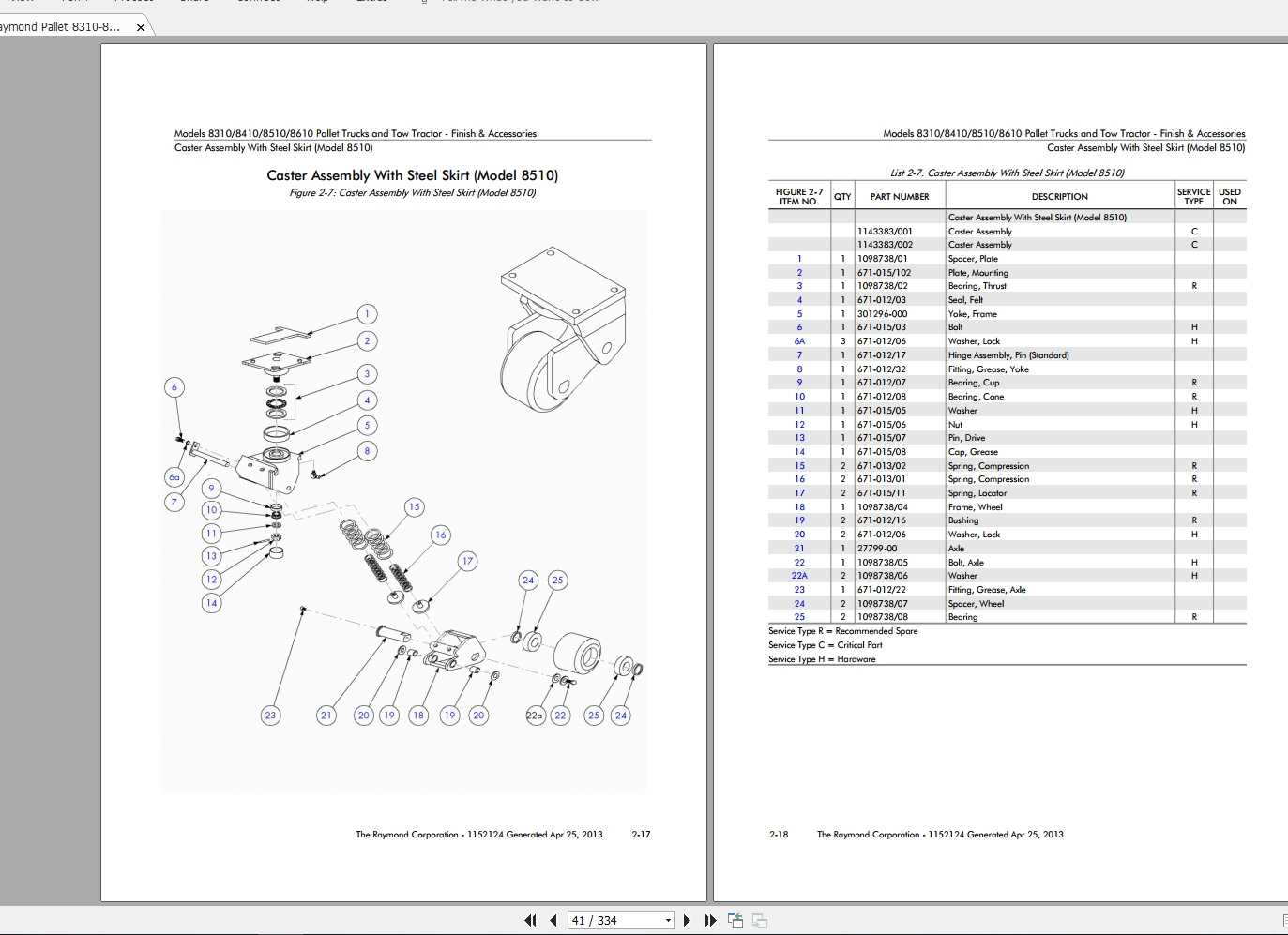
Understanding the inner workings of machinery is essential for both operators and maintenance teams. A well-structured visual representation of components helps to enhance this knowledge, allowing users to quickly identify and assess individual mechanisms. In this section, we delve into the importance of such technical visuals for managing equipment upkeep efficiently.
Detailed breakdowns provide clarity on how various mechanical elements are interconnected. By referencing these resources, you can more easily identify key elements and address any potential issues. Whether you’re conducting repairs or regular inspections, having access to clear visual references ensures smoother processes and reduces the risk of errors.
Moreover, utilizing accurate technical illustrations streamlines the identification of specific components and simplifies the process of sourcing replacements. This makes maintenance tasks more intuitive and helps avoid unnecessary downtime in operations.
Understanding the Raymond 8210 Components
In order to ensure optimal functionality and long-term performance, it’s important to become familiar with the essential elements of this electric pallet truck model. Each component contributes to the overall efficiency of the machine, allowing it to handle daily tasks effectively. A comprehensive understanding of these elements can help with both maintenance and troubleshooting.
Key Structural Elements
- Power unit: The central source of energy that powers the equipment, driving its core functions.
- Control handle: This part allows for smooth steering and maneuvering, ensuring precise direction control during operation.
- Fork assembly: Designed for handling and lifting, this component supports various load sizes with ease.
Electrical Components
- Battery system: Provides the necessary electrical power, ensuring that the machine operates efficiently over extended periods.
- Motor: Drives the movement of the vehicle and enables the lifting mechanism, offering consistent power for both functions.
- Wiring and controls: These connect all the electrical systems, allowing for seamless communication between different parts of the vehicle.
Key Parts of the Raymond 8210 Pallet Jack

The electric pallet jack is designed for efficient and safe movement of goods within warehouse environments. To ensure its reliable operation, it incorporates various essential elements that work in tandem. This section provides a detailed overview of the main components and their respective functions, contributing to the overall performance of the equipment.
Core Components
- Power Unit: The driving force behind the equipment, powering both movement and lifting capabilities.
- Hydraulic System: Responsible for lifting and lowering the forks, ensuring smooth operation.
- Control Handle: This part allows the operator to steer and control the equipment with ease.
Additional Features
- Battery Pack: Provides the necessary energy for the unit’s electrical systems and prolonged operation.
- Fork Assembly: The structure that holds and supports loads, enabling transport.
- Safety
Overview of the Electrical System Diagram
The electrical system of this equipment is essential for its overall functionality, ensuring smooth operation and control. By understanding its layout, you can identify key connections, power flows, and safety mechanisms. This section highlights the key components and how they interact within the system, emphasizing efficiency and proper functioning.
Key Power Components
At the heart of the electrical system lies the power distribution network, which manages the flow of energy between various elements. Key units include the battery, control modules, and switches, all working together to maintain continuous power supply. Each element plays a critical role in maintaining balance and ensuring reliable performance.
Control and Safety Features
Another crucial aspect is the integration of control systems and safety measures. These systems monitor the equipment’s performance, ensuring that no overloads or malfunctions occur. By understanding how control circuits are designed, operators can better manage and troubleshoot issues when needed.
How the Drive Motor Operates
The drive motor is a critical component responsible for converting electrical energy into mechanical movement. This process powers the vehicle, allowing it to perform various tasks efficiently. By understanding how the motor functions, one can gain insight into the overall mechanism and maintenance of the system.
Energy Conversion Process
At the heart of the motor’s operation is its ability to convert energy. The electrical input is transformed into rotational motion, which powers the wheels. This rotational energy is essential for the movement and control of the equipment. The efficiency of this conversion is influenced by several factors, including the type of motor and the quality of the electrical current.
- Electricity flows into the motor from the power source.
- The motor’s internal components create magnetic fields.
- These magnetic fields generate torque, which drives the motion.
Control and Regulation
The speed and direction of the motor are managed by a control system. This system ensures that the vehicle operates smoothly and responds accurately to the operator’s commands. Adjustments in speed, braking, and direction are achieved through precise regulation of the electrical signals sent to the motor.
- Signals from the con
Exploring the Steering Mechanism
The steering system is a crucial component that allows for precise control and maneuverability. It plays a vital role in ensuring the smooth navigation of equipment, enabling operators to handle the machine efficiently even in tight spaces. Understanding how this system functions provides valuable insights into its maintenance and optimization.
Key Components of the Steering System
- Steering Column – The main support structure that connects the operator’s input to the wheels.
- Steering Wheel – Provides the interface for controlling direction.
- Hydraulic Actuators – Essential for applying force to turn the wheels.
- Control Unit – Regulates the hydraulic pressure for smooth steering.
Steering Mechanism Functionality
- The operator adjusts the steering wheel to determine the desired direction.
- Signals from the control unit guide the actuators to apply necessary force.
- The wheels respond to this force, allowing the equipment to move accurately
Brake System Components and Functions
The brake system is a critical aspect of any industrial vehicle, ensuring safety and control during operation. It comprises various elements that work together to slow down or stop the vehicle efficiently. Understanding these components and their roles is essential for effective maintenance and troubleshooting.
Key Components of the Brake System
The primary elements of the braking mechanism include the brake pads, rotors, calipers, and hydraulic lines. Each part plays a significant role in generating the necessary friction to halt the vehicle’s movement. Brake pads are designed to press against the rotors, creating the force needed to slow down. Calipers house the pads and utilize hydraulic pressure to apply them effectively.
Functions and Importance

The functionality of the brake system directly impacts the safety of the vehicle. Properly maintained components ensure reliable stopping power, reducing the risk of accidents. Regular inspection and timely replacement of worn-out parts are crucial for optimal performance. Understanding the importance of each component aids in recognizing potential issues before they escalate, contributing to overall operational efficiency.
Hydraulic System Breakdown
The hydraulic system is a crucial component in many industrial vehicles, enabling smooth and efficient operation through fluid power. Understanding its configuration and functionality is essential for effective maintenance and troubleshooting. This section provides an overview of the key elements involved in hydraulic systems and their roles in enhancing vehicle performance.
Key Components
- Hydraulic Pump: Converts mechanical energy into hydraulic energy, generating fluid flow.
- Actuators: Devices that convert hydraulic energy into mechanical motion, such as cylinders or motors.
- Hoses and Fittings: Essential for transporting hydraulic fluid between components, ensuring safe and efficient operation.
- Reservoir: Stores hydraulic fluid, allowing for proper pressure maintenance and fluid replenishment.
- Control Valves: Regulate the flow and direction of hydraulic fluid, enabling precise control over various functions.
Common Issues
- Fluid Leaks: Often caused by damaged hoses or fittings, leading to decreased efficiency and potential system failure.
- Air Contamination: Ingress of air into the hydraulic fluid can cause erratic system performance and reduced power transmission.
- Filter Blockages: Clogged filters can restrict fluid flow, causing overheating and reduced responsiveness.
Importance of the Battery and Charger Setup
The configuration of power sources and charging mechanisms plays a crucial role in the functionality and efficiency of equipment. Proper management of these elements ensures optimal performance and longevity, minimizing downtime and maintenance costs.
Effective energy storage and retrieval systems not only provide the necessary power for operations but also enhance safety and reliability. Understanding the specifications and compatibility of batteries and chargers can significantly impact operational efficiency.
Aspect Importance Energy Efficiency Maximizes operational time and reduces energy waste. Battery Lifespan Proper charging prevents degradation, extending usage life. Safety Reduces the risk of overheating or failures during operation. Compatibility Ensures optimal performance and prevents equipment damage. Role of the Control Handle in Operations
The control handle serves a crucial function in the maneuverability and efficiency of material handling equipment. It acts as the primary interface between the operator and the machine, allowing for seamless execution of various tasks. By facilitating direct communication with the device’s control system, it enhances operational precision and user comfort.
Properly designed control handles enable intuitive navigation, significantly reducing the learning curve for new operators. Ergonomically shaped handles can minimize physical strain during prolonged use, promoting safety and productivity. Moreover, the responsiveness of the control handle can influence the overall performance of the equipment, ensuring that operators can react swiftly to changing conditions on the worksite.
Examining the Load Wheels and Casters
The functionality and stability of material handling equipment significantly rely on the components that facilitate movement. In particular, the load wheels and casters play a crucial role in ensuring smooth operation and efficiency. Understanding these elements helps in maintaining optimal performance and prolonging the lifespan of the machinery.
Load wheels are designed to support the weight of the equipment while providing maneuverability. Key aspects to consider include:
- Material Composition: Different materials can affect durability and traction.
- Wheel Diameter: Larger wheels generally improve rolling resistance and enhance movement over uneven surfaces.
- Load Capacity: Each wheel must be rated to handle specific weights for safe operation.
Casters also contribute to overall mobility and can vary in design and functionality. When assessing casters, focus on the following:
- Swivel vs. Rigid: Swivel casters allow for easier maneuvering, while rigid casters offer stability in straight paths.
- Brake Systems: Effective brakes ensure safety when the equipment is stationary.
- Mounting Style: Compatibility with the equipment frame is essential for secure attachment.
Regular inspection and maintenance of load wheels and casters not only enhance performance but also prevent unexpected breakdowns. Keeping these components in good condition is vital for the overall efficiency of the equipment.
Safety Features in the Raymond 8210 Design
The design of modern industrial equipment prioritizes user safety through various innovative features. These enhancements not only protect operators but also promote a secure working environment, reducing the risk of accidents during operation. Understanding these attributes is essential for maximizing both efficiency and safety in daily tasks.
One notable aspect is the incorporation of advanced stability mechanisms. These systems ensure the equipment remains balanced, even when handling heavy loads or navigating uneven surfaces. This stability minimizes the likelihood of tipping and enhances overall operational control.
Additionally, the inclusion of ergonomic elements is crucial. Thoughtful design reduces strain on the user, allowing for more comfortable operation over extended periods. This consideration not only aids in reducing fatigue but also plays a vital role in maintaining alertness and focus during work.
Another significant feature involves comprehensive visibility enhancements. Strategic placement of windows and mirrors provides operators with an unobstructed view of their surroundings, enabling better situational awareness. This aspect is particularly important in busy environments where multiple tasks and personnel are present.
Moreover, intuitive control layouts contribute to safer operation. By placing controls within easy reach and clearly labeling functions, the likelihood of operator error diminishes. This design philosophy fosters confidence and ensures that users can respond quickly to any potential hazards.
In summary, the emphasis on safety within the equipment’s design reflects a commitment to protecting users while enhancing productivity. These thoughtful features combine to create a reliable and secure operational experience, underscoring the importance of safety in industrial settings.
Troubleshooting Common Part Failures
When dealing with machinery, understanding and resolving frequent component malfunctions is essential for maintaining optimal performance. Addressing these issues promptly can prevent further damage and ensure the longevity of the equipment. Below are some common failures and troubleshooting steps that can aid in efficient resolution.
- Battery Issues:
- Check for proper connections and corrosion.
- Test the voltage to ensure it meets required levels.
- Inspect for any signs of swelling or leakage.
- Drive System Problems:
- Listen for unusual noises during operation, indicating wear.
- Check belts and chains for signs of fraying or misalignment.
- Inspect gears for damage or excessive play.
- Hydraulic Failures:
- Monitor for fluid leaks around hoses and connections.
- Check the fluid levels and quality regularly.
- Inspect cylinders for signs of wear or damage.
- Electrical Component Failures:
- Test fuses and circuit breakers for continuity.
- Inspect wiring for frays or loose connections.
- Verify the operation of switches and sensors.
By systematically addressing these common failures, operators can significantly reduce downtime and improve the efficiency of their equipment. Regular maintenance and keen observation are key to identifying issues early and ensuring reliable operation.