Maintaining the efficiency and longevity of your landscaping equipment depends greatly on knowing how its various elements fit together. Whether you’re troubleshooting an issue or performing regular maintenance, being familiar with the structure of the machine will help you navigate the intricacies with ease.
Each section of a high-performance mower is meticulously designed to work in harmony, ensuring smooth operation. Recognizing the layout and connection points of these elements enables owners to quickly identify and address any mechanical challenges.
This guide provides detailed insights into the essential features
Overview of Key Components for Scag Tiger Cub 48
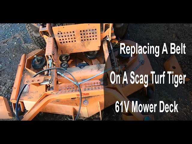
In this section, we will explore the essential elements that contribute to the functionality of this high-performance machine. Each part is designed to work in harmony, ensuring efficiency and reliability for various outdoor tasks. Understanding how these individual components operate and interact can help in maintaining the system’s performance.
Primary Drive System
The drive mechanism plays a crucial role in ensuring smooth motion. It consists of several moving parts that control speed, direction, and stability. Regular maintenance of these components can greatly extend the machine’s longevity.
Cutting Mechanism
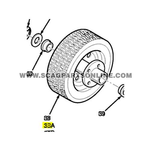
The cutting system is designed for precision and durability. It incorporates blades, belts, and adjustment points, all of which require occasional inspection to ensure optimal performance. Proper alignment and sharpness of the blades are critical
Engine and Drive System Layout
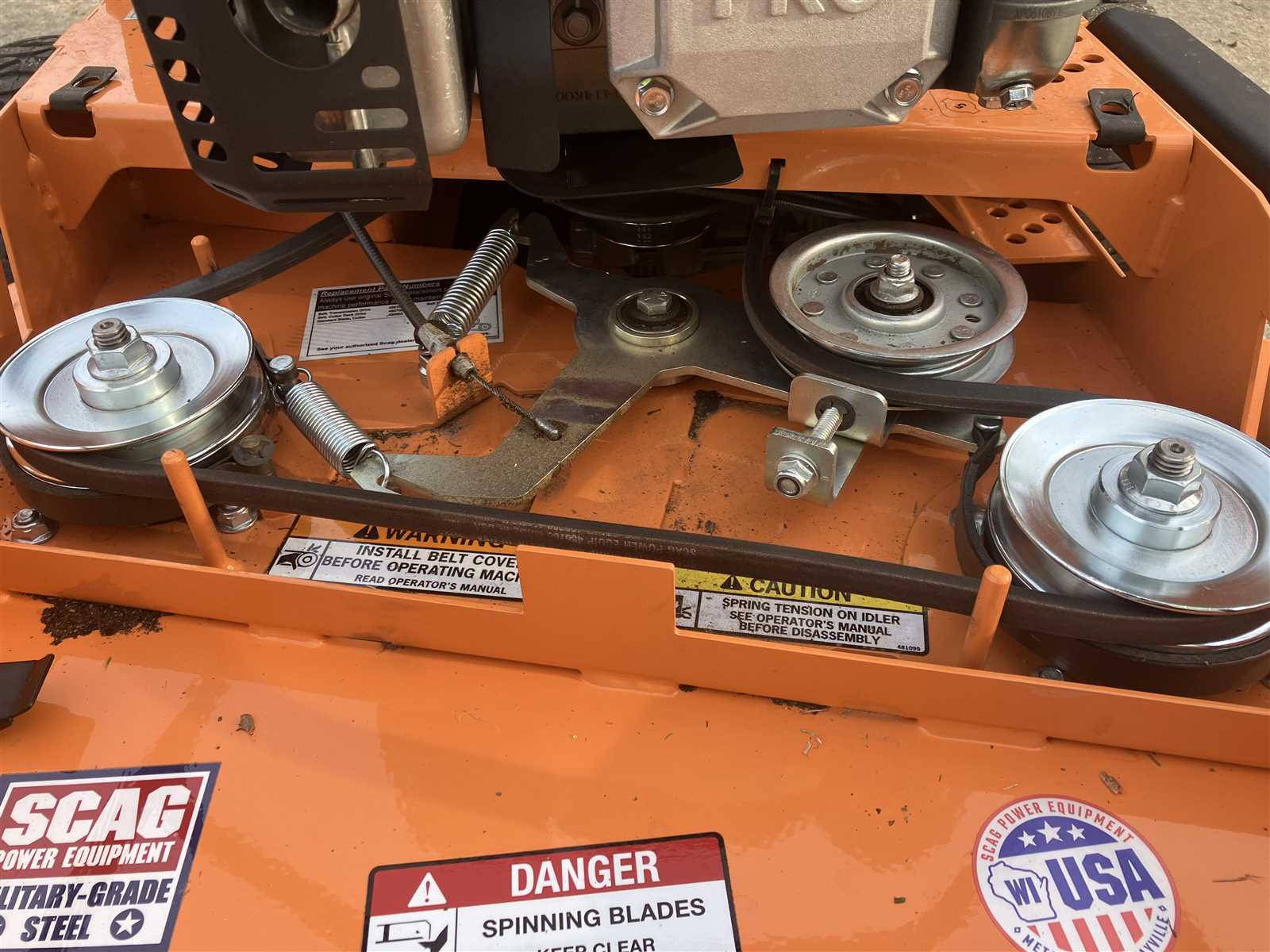
The power unit and motion transmission system work in harmony to ensure smooth operation and optimal performance. Understanding the positioning and interaction of these components helps with effective maintenance and troubleshooting.
| Component | Function | |||||||||||||||||||||||||||
|---|---|---|---|---|---|---|---|---|---|---|---|---|---|---|---|---|---|---|---|---|---|---|---|---|---|---|---|---|
| Engine Block | Serves as the central power source, converting fuel into mechanical energy. | |||||||||||||||||||||||||||
| Transmission | Transmits the engine’s power to the wheels, allowing for efficient movement and speed control. | |||||||||||||||||||||||||||
| Hydraulic Pumps |
| Component | Function |
|---|---|
| Steering Wheel | Allows the operator to control the direction of the machine. |
| Linkages | Connect the steering wheel to the wheels, enabling movement transfer. |
| Control Levers | Facilitate the adjustment of speed and cutting height. |
Maintenance Considerations
Regular inspection and maintenance of the steering and control assembly are vital to ensure optimal performance. Components should be checked for wear and tear, and any necessary adjustments should be made to maintain smooth operation.
Transmission and Hydraulic System Overview
The transmission and hydraulic system are vital components that ensure the efficient operation of the machine. These systems work in tandem to provide the necessary power and control required for various tasks, enabling the equipment to navigate challenging terrains and handle different mowing conditions. Understanding their functionality and layout is essential for maintenance and troubleshooting.
Hydraulic Mechanism
The hydraulic mechanism utilizes fluid power to generate force, allowing for precise control of various functions. This system typically consists of pumps, hoses, and cylinders, which work together to convert hydraulic energy into mechanical movement. Regular checks and maintenance of the hydraulic fluid levels and components are crucial for optimal performance.
Transmission Functionality
The transmission system is responsible for transferring power from the engine to the wheels or cutting deck. It usually features gear ratios that can be adjusted to match the operating conditions, providing the flexibility to maneuver effectively. Proper adjustment and maintenance of this system can significantly enhance the overall efficiency and longevity of the equipment.
Seat and Operator Control Panel Configuration
The arrangement of the seating and control interface is crucial for ensuring optimal user experience and safety. A well-designed operator environment allows for ease of use, enhancing productivity while minimizing operator fatigue during extended periods of operation. This section focuses on the configuration of the seating arrangement and the layout of the control panel.
Operator Seat: The seat should provide adequate support and comfort, allowing the operator to maintain a proper posture. Adjustable features such as seat height and tilt can help accommodate different body types, ensuring that all operators can find a comfortable position. Additionally, incorporating high-quality cushioning materials will enhance the overall experience, especially during prolonged use.
Control Panel Layout: The arrangement of controls should prioritize accessibility and usability. All essential controls must be within easy reach, allowing operators to adjust settings without having to shift their position. Grouping similar functions together can further streamline operation. Clear labeling and intuitive design are essential to reduce the learning curve for new users.
Safety Features: Safety is paramount in any operational setup. The configuration should include easily accessible emergency shut-off switches and clear visibility of important indicators. Ensuring that these features are integrated into the design will help to prevent accidents and enhance the overall safety of the equipment.
In conclusion, a thoughtfully designed seating and control panel configuration significantly contributes to the efficiency and safety of operation. By focusing on ergonomic design and intuitive layouts, manufacturers can enhance user satisfaction and operational effectiveness.
Wiring and Electrical Component Mapping
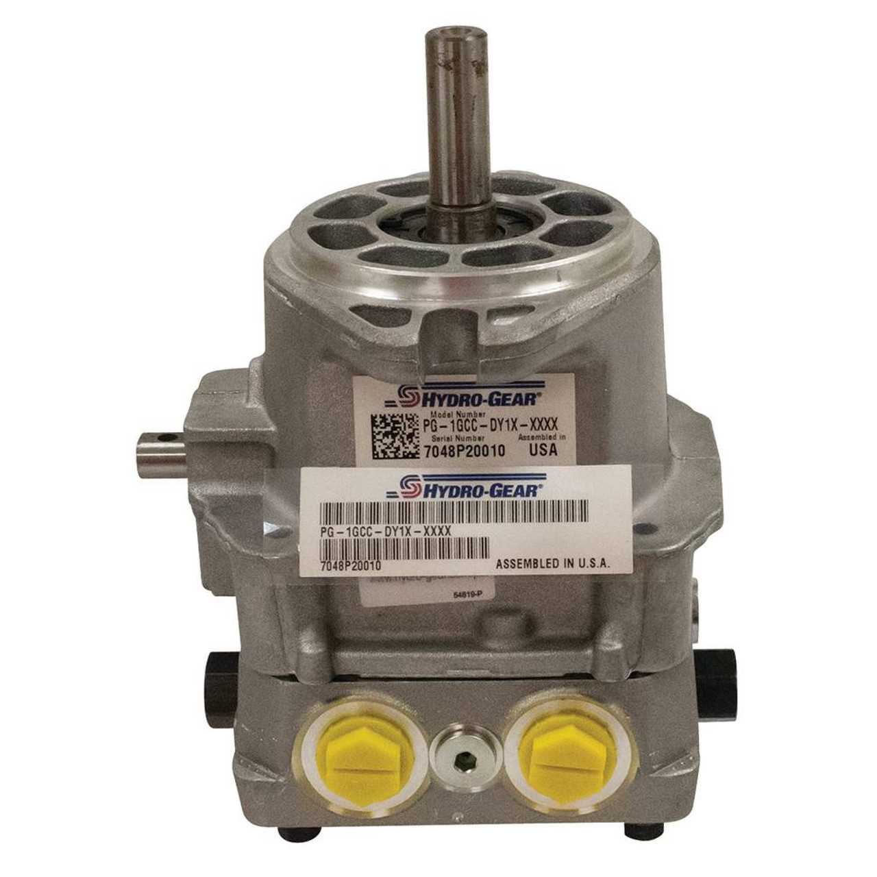
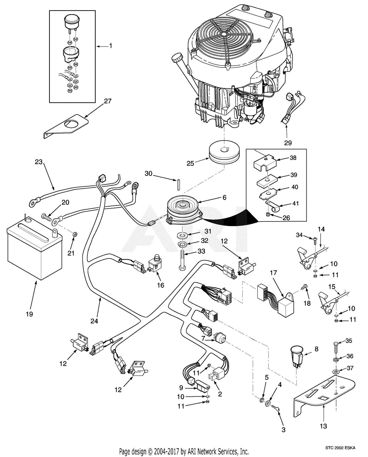
This section provides an overview of the electrical system layout and wiring configuration within a specific mower model. Understanding the connections and component arrangement is crucial for effective troubleshooting, maintenance, and enhancement of the machine’s performance.
Key Electrical Components
- Battery: Supplies power to the electrical system.
- Ignition Switch: Controls the starting and stopping of the engine.
- Fuses: Protect the wiring by preventing overloads.
- Relays: Act as switches for high-power circuits, controlled by lower-power signals.
- Motors: Drive various components such as blades and wheel systems.
Wiring Configuration Overview
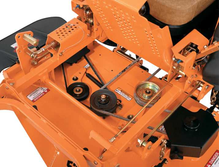
- Identify the main power source and its connection to the ignition switch.
- Trace the wiring from the ignition switch to various components, noting any critical junctions.
- Ensure all safety devices are correctly wired to prevent accidents.
- Verify that relays are in place to manage power distribution effectively.
- Inspect the connections between motors and control panels for signs of wear or damage.
Deck and Suspension Parts Layout
The arrangement of the mowing assembly and suspension components plays a crucial role in the overall performance and stability of lawn maintenance equipment. Understanding the configuration of these elements is essential for effective maintenance and repair, ensuring optimal functionality during operation.
This section outlines the key components found within the mowing assembly and suspension system, highlighting their specific functions and interactions:
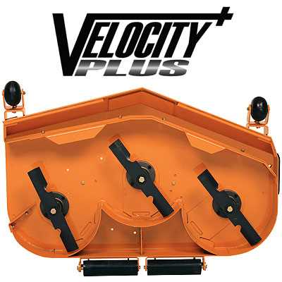
- Mowing Deck: The main structure responsible for cutting grass, which houses the blades and facilitates efficient grass management.
- Blade Assembly: Comprising rotating cutting tools that perform the actual grass trimming, positioned within the deck for optimal performance.
- Deck Suspension System: A framework designed to absorb shocks and vibrations, ensuring a smooth operation and protecting the mower’s integrity.
- Spindles: Components that support the blade assembly, allowing for rotation and ensuring a precise cutting height.
- Anti-scalp Rollers: Positioned at the front or sides of the deck to prevent scalping of the turf, enhancing the quality of the cut.
- Lift Mechanism: A system that enables the operator to adjust the deck height for various mowing conditions and terrain types.
By familiarizing oneself with the layout and functionality of these elements, users can enhance the efficiency and longevity of their lawn care equipment.
Exhaust and Cooling System Arrangement
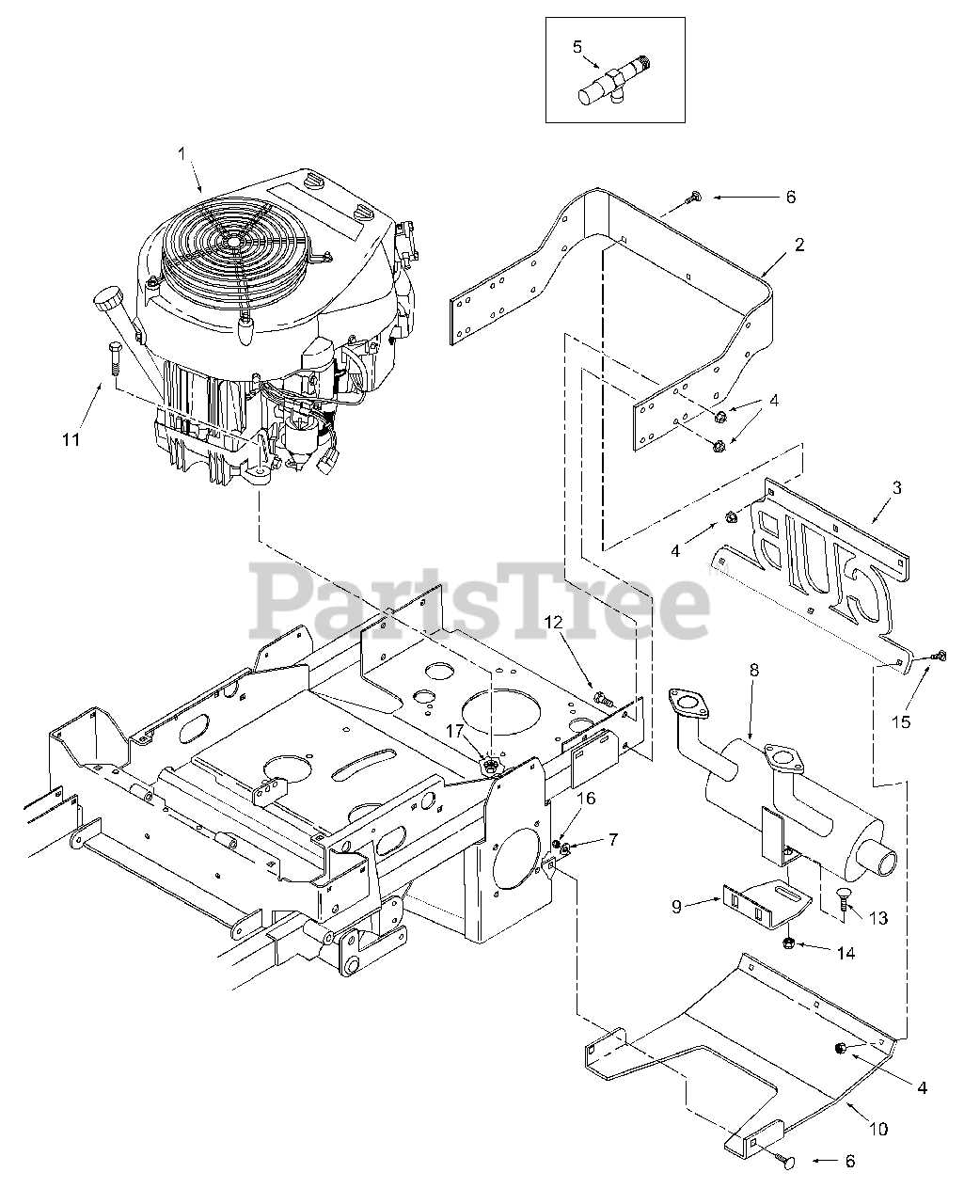
The arrangement of the exhaust and cooling systems plays a crucial role in the overall performance and efficiency of the machinery. These systems are designed to manage heat dissipation and ensure optimal engine operation by facilitating the removal of exhaust gases and regulating temperatures. Understanding the configuration of these systems helps in maintaining engine health and enhancing longevity.
Exhaust System Components
The exhaust mechanism comprises several integral components that work collaboratively to channel gases away from the engine. These parts not only minimize emissions but also contribute to the smooth functioning of the machine.
| Component | Description |
|---|---|
| Exhaust Manifold | Collects exhaust gases from the engine cylinders and directs them to the exhaust pipe. |
| Exhaust Pipe | Transports gases from the manifold to the atmosphere, ensuring efficient flow. |
| Muffler | Reduces noise produced by the exhaust gases while allowing for proper gas exit. |
| Catalytic Converter | Transforms harmful gases into less harmful emissions before release. |
Cooling System Functionality
Effective temperature regulation is achieved through a carefully designed cooling system. This setup prevents overheating and maintains the engine at an optimal operating temperature, thereby enhancing performance and reliability.
| Component | Description |
|---|---|
| Radiator | Dissipates heat from the coolant to the atmosphere, ensuring effective cooling. |
| Cooling Fan | Enhances airflow through the radiator to improve cooling efficiency. |
| Water Pump | Circulates coolant through the engine and radiator for temperature control. |
| Thermostat | Regulates coolant flow based on temperature, maintaining an optimal engine temperature. |
Maintenance Access Points and Service Areas
Proper upkeep of equipment is essential for optimal performance and longevity. Recognizing key access locations and designated service zones can significantly enhance the maintenance process. These areas are specifically designed to facilitate easy access to critical components, ensuring that routine checks and repairs can be performed efficiently and effectively.
Identifying Access Points
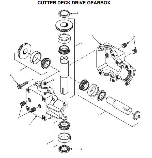
Access points are strategically located to allow quick and straightforward servicing of various components. These locations typically include openings for oil changes, air filters, and battery checks. Ensuring these points are unobstructed is vital for maintaining accessibility and expediting the maintenance workflow. Regular inspection of these areas will help prevent potential issues and ensure that the machinery operates smoothly.
Service Area Importance
The designated service areas provide ample space for performing maintenance tasks safely and efficiently. These zones are typically equipped with the necessary tools and equipment, allowing for a comprehensive approach to upkeep. It is essential to maintain cleanliness in these areas to prevent contamination and ensure that all tasks can be completed without unnecessary delays. Establishing a regular maintenance schedule will also contribute to the longevity of the equipment and help avoid costly repairs.
