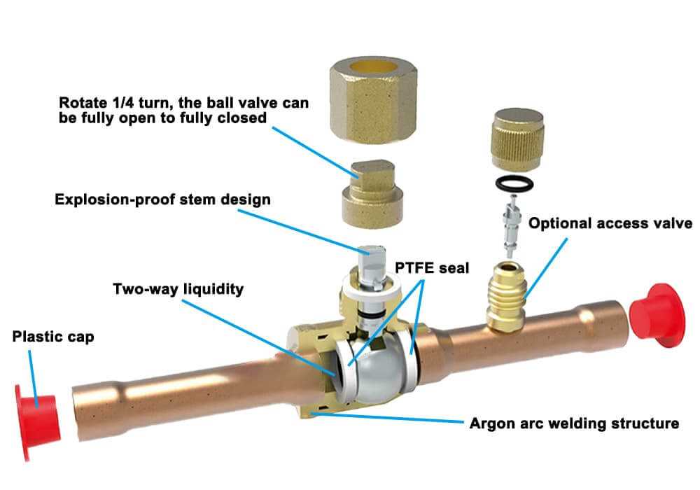
The functionality of fluid regulation systems relies on a combination of essential elements that work together to ensure proper management of liquid or gas movement. Knowing how these components interact is key to maintaining optimal performance and avoiding issues in different setups.
In order to ensure effective regulation, it is crucial to have a detailed understanding of how each piece contributes to the overall process. This knowledge aids in diagnosing issues and performing maintenance with confidence, especially when dealing with complex mechanisms that control the flow of fluids or gases.
By exploring the structure and role of individual elements within this system, one can gain a deeper appreciation for how precision is achieved in managing pressure and flow rates. This understanding not only enhances troubleshooting skills but also helps in ensuring
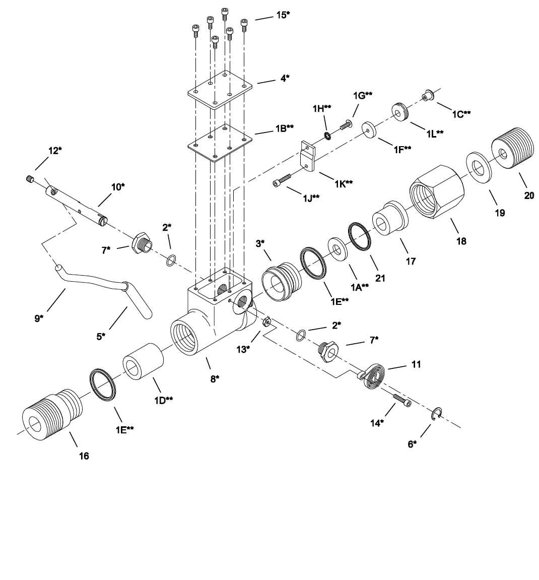
Shut Off Valve Components Overview
The mechanism responsible for controlling the flow of liquids or gases consists of several key elements that work together to ensure proper functionality. Each piece plays a vital role in maintaining control over the system, ensuring smooth operation and reliable performance. Understanding these elements is crucial for both maintenance and troubleshooting.
Control Handle: This external part allows for easy manipulation of the internal mechanism, adjusting the flow direction or completely stopping it when needed. It provides users with manual control over the system.
Sealing Unit: Positioned within the structure, this component ensures that when the system is in a closed state, no leaks occur. The quality and integrity of the seal are essential for preventing unwanted fluid or gas passage
Main Shut Off Valve Functions
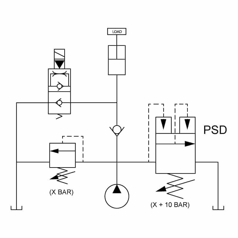
The primary device responsible for controlling the flow of liquids or gases in a system plays a crucial role in maintaining the safety and efficiency of various operations. This component ensures that the movement of fluids can be easily regulated, either fully allowing or stopping the flow as needed, depending on the requirements of the system.
Flow Control and Safety
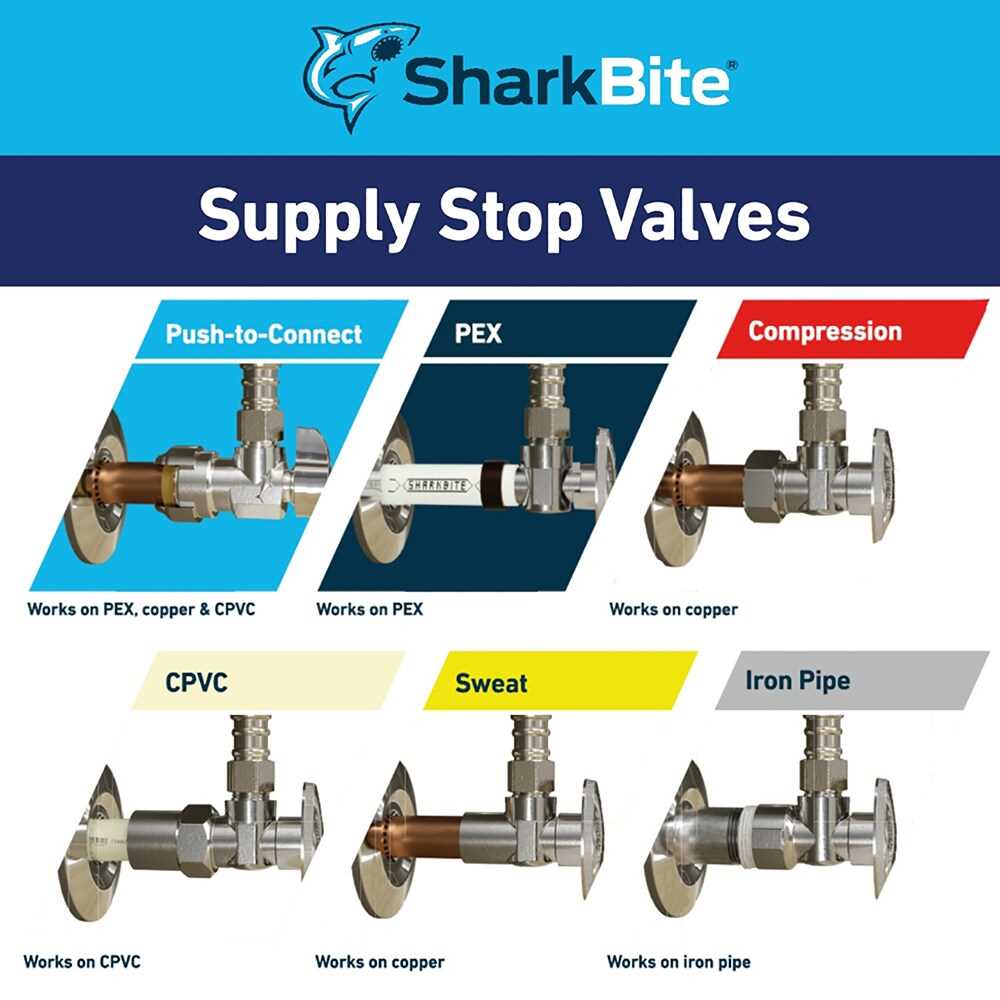
One of the key functions of this component is to provide precise regulation over the flow. It is often used to isolate certain sections of a pipeline, enabling maintenance work or emergency interventions without disrupting the entire network. Additionally, this control mechanism is essential for preventing accidental spills or leaks, contributing to overall system safety.
System Maintenance and Efficiency
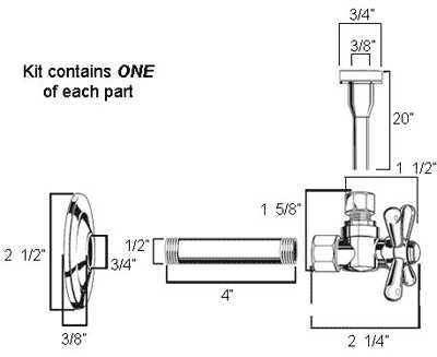
By effectively managing the direction and quantity of fluid movement,
Key Internal Elements of Shut Off Valves
The internal structure of flow control mechanisms is composed of several essential components that ensure proper functionality. These elements work together to regulate the movement of fluids, ensuring reliable operation and durability over time.
Core mechanisms include adjustable components that manage the flow, pressure, and sealing capabilities. These parts often feature resilient materials to withstand different environmental conditions, ensuring the device’s longevity and effectiveness.
Sealing components are crucial for preventing leaks. They are designed to provide a tight closure, minimizing fluid escape and maintaining system integrity. Durable materials are typically used to enhance their performance under stress.
Common Materials Used in Valve Construction
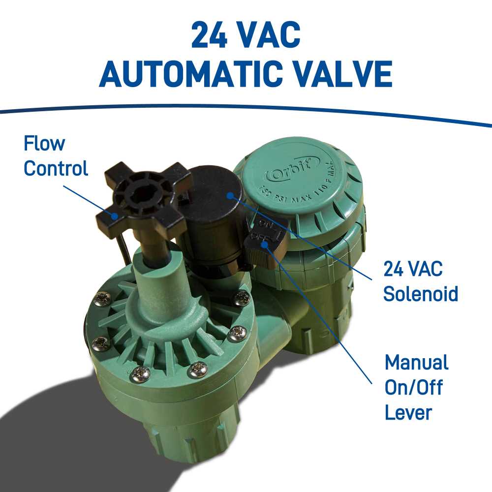
In the design and production of flow control components, selecting the right materials is crucial to ensure durability, performance, and compatibility with various substances. These materials are chosen based on their resistance to corrosion, strength, and ability to withstand different environmental conditions.
- Stainless Steel: Known for its excellent corrosion resistance and strength, stainless steel is commonly used in industrial applications where exposure to harsh chemicals or high temperatures is common.
- Brass: Brass offers a balance of strength, corrosion resistance, and ease of machining, making it suitable for components exposed to water, oil, and mild chemicals.
- Plastic: High-performance plastics such as PVC or PTFE are lightweight, resistant to corrosion, and
Differences Between Manual and Automatic Valves
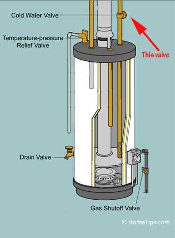
There are two primary types of flow control mechanisms used in various systems: manual and automatic. Each has distinct features and is suited for different applications depending on the level of control and automation required. Understanding their differences can help in choosing the right one for specific operational needs.
Manual Valves
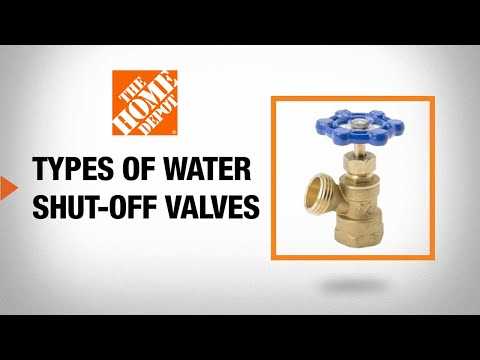
Manual control devices are operated by hand, often requiring physical effort to regulate the flow. These are simple, durable, and cost-effective, making them a common choice in systems where frequent adjustments are not needed.
- Simple to install and maintain
- No external power source required
- Reliability in environments without complex automation
Automatic Valves
Valve Sealing Mechanisms and Types
Sealing mechanisms play a crucial role in ensuring the integrity and efficiency of various flow control devices. These systems are designed to prevent leaks and maintain pressure, which is essential for the proper functioning of industrial and residential applications. Understanding the different types of sealing solutions can significantly enhance performance and reliability.
Compression Seals are among the most common types used in sealing mechanisms. They work by compressing a material, such as rubber or elastomer, against a surface to create a tight seal. This method is highly effective for applications requiring a strong barrier against liquids and gases.
O-Rings are another popular sealing solution. These circular rings, made of flexible materials, fit snugly into grooves and create a seal when compressed. O-rings are widely used due to their simplicity, cost-effectiveness, and versatility across various pressure and temperature ranges.
Gaskets are flat sealing devices that can be made from various materials, including rubber, metal, or composite substances. They are utilized in applications where two surfaces come together, providing a reliable seal to prevent leaks. Gaskets are often employed in flanged connections and joint assemblies.
Diaphragms are flexible membranes used to create a barrier between different mediums. They can adapt to changes in pressure and are particularly effective in controlling flow in sensitive applications. Their ability to flex and return to shape makes them suitable for many industrial processes.
In summary, the choice of sealing mechanism is critical for optimizing performance and preventing leaks. By selecting the appropriate type, users can enhance the longevity and effectiveness of their flow control devices.
Importance of the Valve Stem in Operation
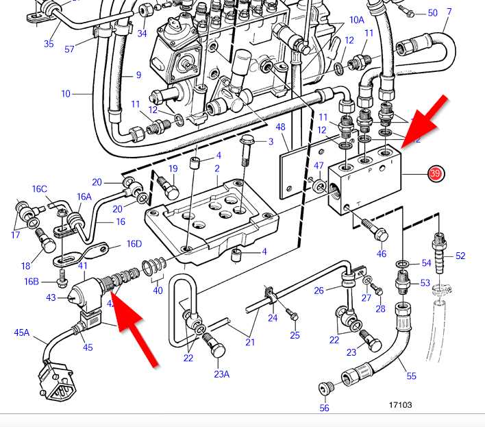
The component responsible for controlling the flow of fluids plays a crucial role in ensuring efficient operation within various systems. It serves as the primary mechanism for regulating movement, allowing for precise adjustments and reliable performance. Understanding the significance of this element is essential for maintaining optimal functionality and preventing potential issues.
Role in Fluid Regulation
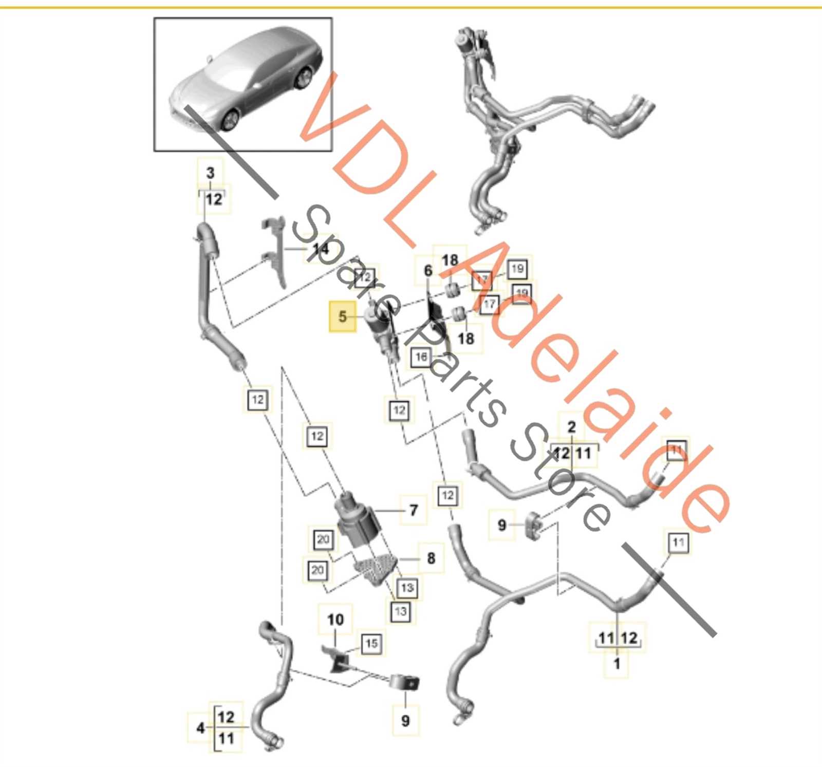
The mechanism facilitates the opening and closing of passages, enabling the desired flow rate to be achieved. Its design directly impacts the overall effectiveness of the system, making it vital for maintaining desired pressure levels and preventing leaks. A well-functioning component can significantly enhance system reliability and longevity.
Maintenance and Longevity
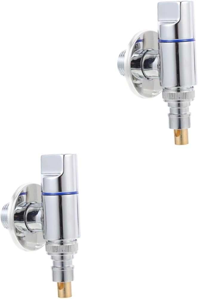
Regular inspection and maintenance of this element are necessary to ensure its proper function. Wear and tear can lead to operational failures, making it essential to address any signs of degradation promptly. By prioritizing the upkeep of this mechanism, operators can prolong the lifespan of the entire assembly and enhance performance.
Gaskets and O-Rings in Shut Off Valves
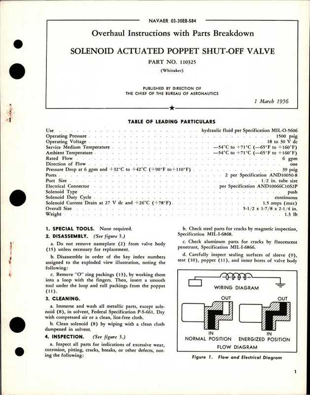
Gaskets and O-rings play a crucial role in ensuring the functionality and efficiency of various control mechanisms. These components serve as essential sealing elements that prevent leakage and maintain pressure within the system. Their proper selection and maintenance are vital for the overall performance and longevity of these devices.
Gaskets are typically flat sealing elements designed to fill the space between two or more surfaces, ensuring a tight seal. They are available in a variety of materials, each offering different levels of resistance to temperature, pressure, and chemical exposure. Choosing the right material is critical for optimal performance in specific environments.
O-rings, on the other hand, are circular seals that fit into grooves to provide a secure seal between cylindrical surfaces. They are widely used due to their simple design and effectiveness. The choice of size and material significantly impacts their sealing capability, making it important to match them correctly to the application.
In summary, both gaskets and O-rings are integral components that contribute to the reliable operation of control mechanisms. Regular inspection and timely replacement of these sealing elements can help prevent issues such as leaks and malfunctions, ensuring the longevity and efficiency of the overall system.
Signs of Wear in Valve Components
Over time, the functionality of control mechanisms can diminish due to various factors. Understanding the indicators of degradation is essential for maintaining optimal performance and ensuring safety in systems. Recognizing these signs can help prevent failures and extend the lifespan of the components involved.
Visual Indicators
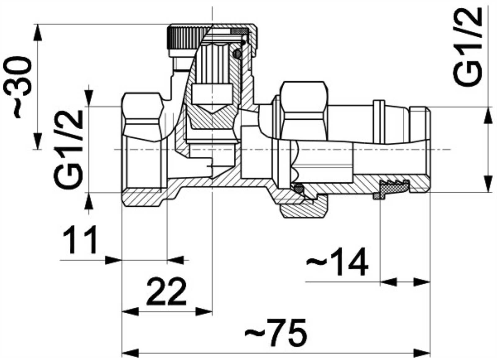
One of the most immediate ways to identify wear is through visual inspection. Look for signs such as discoloration, cracks, or surface erosion. These visual cues often indicate that the material is weakening and may need replacement. Additionally, any unusual buildup of deposits can also signal that the mechanism is not functioning as intended.
Functional Changes
Changes in operational efficiency can be a clear sign of internal issues. If components begin to respond sluggishly or inconsistently, it could be a result of wear. Unusual noises during operation, such as grinding or rattling, can also indicate that parts are not engaging correctly. Regular maintenance and monitoring can mitigate these issues before they lead to complete malfunction.
Maintenance Tips for Longevity
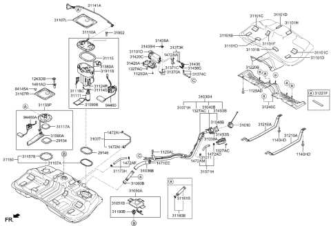
Ensuring the durability of your system requires regular care and attention. Implementing effective maintenance practices not only extends the lifespan of components but also enhances overall performance. Adopting a proactive approach can significantly reduce the likelihood of unexpected failures and costly repairs.
Begin with routine inspections to identify wear and tear. Regularly check for leaks, corrosion, or any signs of deterioration. Cleaning components to remove debris and buildup is essential to maintain optimal functionality. Additionally, lubricating moving parts will help prevent friction and ensure smooth operation.
Following the manufacturer’s guidelines for maintenance schedules is crucial. Adhering to these recommendations will provide a structured approach to care, helping you address potential issues before they escalate. Documenting maintenance activities can also be beneficial for tracking performance and scheduling future checks.
Incorporating these practices into your routine will promote a reliable and efficient system, ensuring that each component performs as intended for years to come.
How to Identify
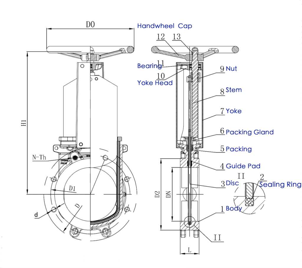
Recognizing the components of a control mechanism is essential for effective maintenance and troubleshooting. Familiarity with the various elements can facilitate prompt identification of issues, ensuring optimal operation of the system.
Begin by examining the configuration of the mechanism. Each element typically serves a distinct function, contributing to the overall performance. Look for key features such as shapes, sizes, and material compositions that can offer clues about their specific roles.
Next, consider the connections and interactions between the components. Understanding how they work together will aid in pinpointing any discrepancies or malfunctions. Pay attention to any markings or labels, as these can provide additional information about the individual parts.
Finally, consult reference materials or schematics related to the mechanism. These resources can offer valuable insights and comparisons, enabling you to accurately distinguish each element within the system.