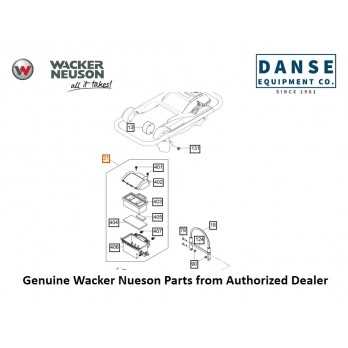
wacker neuson bs50 4 parts diagram

The machinery in question is built to last and perform under demanding conditions, ensuring reliable functionality in diverse environments. In order to maintain or repair this equipment, it is essential to become familiar with its internal structure and the specific elements that contribute to its overall performance. This section will provide a detailed overview of the critical elements that ensure optimal operation and durability.

Each mechanical system consists of carefully arranged elements that work together to deliver power, control, and efficiency. From the driving force behind the engine to the smallest connecting pieces, every part plays a significant role in the system’s stability and functionality. By studying the internal configuration, one can easily identify potential areas for maintenance, replacement, or adjustment.

In the following sections, we will dive deeper into the core components, illustrating their purpose, location, and connection within the system. Whether you’re conducting routine maintenance or troubleshooting a specific issue, understanding these elements will significantly enhance your ability to keep the equipment in top shape.

Understanding Key Components in Wacker Neuson BS50-4

In this section, we will delve into the essential elements that ensure the effective operation of this powerful machine. Each piece works in harmony to deliver robust performance and durability, making it a reliable choice for heavy-duty tasks. Let’s explore the primary components that make up the core of its functionality and how they contribute to its overall efficiency.

Engine Unit

wacker neuson bs50 4 parts diagram

The heart of the system, the engine, provides the necessary power to drive the entire mechanism. Its compact and efficient design allows for continuous use while maintaining fuel efficiency. Regular maintenance and proper fuel quality are key to ensuring smooth operation.

Vibration Mechanism

This component plays a crucial role in delivering the impactful force needed for various applications. By creating rapid, consistent vibrations, it ensures that the machine can compact surfaces effectively, providing high-quality results in a shorter time frame.

Exploring the Engine Assembly Layout

The internal structure of the motor unit is meticulously designed to ensure optimal performance and durability. Understanding the spatial arrangement of various components within this assembly provides insight into its operational efficiency and ease of maintenance. Each section works in harmony to deliver smooth and consistent power output, while also being accessible for routine inspections and repairs.

Component Function Location
Piston Converts fuel combustion into mechanical force Central part of the cylinder block
Crankshaft Transforms linear piston motion into rotational energy Mounted at the base of the engine block
Cylinder Contains the piston and allows controlled fuel ignition Located in the engine core
Carburetor Mixes air and fuel in precise ratios for combustion Attached near the intake system

Guide to Fuel System Configuration

The fuel system plays a crucial role in ensuring optimal performance by managing the intake, flow, and distribution of the fuel needed for efficient operation. Understanding how the system is arranged helps maintain functionality and prevents malfunctions during usage. This section provides a comprehensive overview of the essential components and their roles within the fuel supply framework.

Key Components Overview

At the heart of the fuel system, several elements work together to ensure seamless operation. These include mechanisms responsible for fuel storage, transport, and regulation. Each part plays a vital role in maintaining the balance between fuel intake and energy output.

Flow and Distribution

The distribution of fuel is regulated through a series of interconnected parts that allow for controlled flow. These elements ensure a consistent supply, minimizing interruptions and maximizing operational efficiency. Below is a table that outlines the key components and their functions within the fuel system configuration:

Vibration Control Mechanism Overview

In dynamic equipment, managing oscillation plays a crucial role in maintaining operational efficiency and ensuring durability. The system designed to control vibrations is integral to the machine’s ability to function optimally, reducing unnecessary wear and enhancing overall performance. Understanding how this mechanism works offers insights into the balance of forces that keep the machine stable during operation.

Key Components of the System

At the heart of this control system are several key components working together. A primary element is responsible for absorbing excess energy, ensuring that the internal forces remain balanced. Supporting this is a secondary element that helps in distributing these forces evenly, allowing for smoother functionality and less mechanical strain.

Optimizing Performance

Proper tuning of the vibration management system is critical for maximizing performance. Regular checks and adjustments can improve the efficiency of the equipment, minimizing breakdowns caused by excessive motion. This careful calibration ensures long-term stability, even under demanding conditions.

Clutch and Drive System Breakdown

The mechanics of the clutch and drive assembly play a crucial role in ensuring efficient power transmission. Understanding the key components and their interconnections helps in maintaining optimal performance and reducing potential downtime. This section explores the fundamental elements involved in the operation of this system.

Main Components

  • Clutch Mechanism: Responsible for engaging and disengaging power to the drive unit, ensuring smooth transitions between idle and active states.
  • Drive Shaft: Transfers motion from the power source to the operating components, maintaining consistent energy flow.
  • Belt System: Links the drive shaft to other moving parts, controlling the transmission of power across various points in the assembly.

Key Functions

  1. Power Engagement: The clutch controls when power is applied, ensuring efficient operation and minimizing wear on the internal mechanisms.

  2. Detailed View of the Exhaust System

    The exhaust mechanism plays a crucial role in the overall function, managing the release of gases and ensuring efficient operation. A well-constructed design reduces emissions and maintains optimal performance, ensuring the equipment runs smoothly and efficiently. Understanding the structure of this system is key to diagnosing potential issues and maintaining longevity.

    Components Breakdown

    This system consists of several interconnected sections, each serving a unique purpose. The exhaust manifold directs gases from the engine, while the muffler works to minimize noise and control gas release. Additional elements like gaskets and pipes ensure a secure and leak-free connection between parts.

    Operational Insights

    wacker neuson bs50 4 parts diagram

    During use, the entire assembly must withstand high temperatures and pressure. The materials used are typically chosen for their durability and heat resistance, ensuring minimal wear over time. Proper inspection and maintenance of these parts help avoid malfunctions and extend the lifespan of the system.

    Carburetor and Air Intake System Explanation

    The fuel and air regulation mechanism is crucial for efficient operation of any engine. This section provides an overview of how the mixture of air and fuel is managed, contributing to optimal performance. By ensuring the right balance, the system helps maintain proper combustion and overall efficiency.

    Carburetor Functionality: The key role of this component is to blend air and fuel in the correct ratio before it enters the engine. It adjusts the flow based on throttle input, ensuring smooth operation across various conditions. Different passages and jets help achieve this balance, making sure the mixture is suitable for combustion.

    Air Intake System: The intake channels are designed to allow a clean and steady airflow into the engine. Filters ensure contaminants are removed, while the shape and layout of the system are engineered to reduce turbulence and optimize the air supply. This, in turn, supports better fuel combustion, leading to increased efficiency and power output.

    Handle and Control Lever Setup

    wacker neuson bs50 4 parts diagram

    The configuration of the handle and control lever is designed to provide optimal ease of use and precise maneuverability. Proper setup ensures smooth operation, reducing strain on the user and allowing for effective control in various work conditions.

    • Ensure that the grip is securely fastened to avoid unnecessary movement during operation.
    • Adjust the angle of the handle to match the operator’s height for comfort and efficiency.
    • Check that the control lever moves freely, providing seamless transitions between settings.
    • Regularly inspect the joints and connections for wear to maintain long-term functionality.
    1. Position the handle correctly to maintain balance and reduce fatigue.
    2. Test the responsiveness of the control lever before each use to guarantee safety.
    3. Periodically lubricate moving parts to prevent stiffness in the lever mechanisms.

    Inspection of Protective Covers and Guards

    Regular inspection of safety components is essential for maintaining the integrity and safety of mechanical equipment. Protective covers and guards are crucial elements that ensure operators are safeguarded from moving parts, debris, and other hazards. Proper checks can help detect any damage, wear, or misalignment, which could compromise their effectiveness and lead to accidents or equipment malfunction.

    Key Areas to Inspect

    When inspecting protective covers and guards, attention should be given to both their structural condition and their functionality. Key factors include verifying that no parts are missing or damaged, ensuring secure attachment, and checking that they do not interfere with the operation of the machinery. Ensuring that safety labels are visible and in good condition is equally important for clear communication of potential risks.

Component Function
Fuel Tank Stores the fuel before it is transported through the system.
Fuel Line Transfers fuel from the tank to other parts of the system.
Carburetor Mixes air and fuel in the proper ratio for combustion.
Fuel Filter
Inspection Aspect Action Required
Physical Condition Check for cracks, dents, or missing components
Attachment Security Ensure that covers and guards are securely fastened
Functionality Verify that the guards do not obstruct machinery movement
Visibility of Safety Labels Ensure labels are legible and properly placed

Common Issues and Solutions

During routine checks, you may encounter certain issues, such as cracks in the covers or loose attachments. Cracked covers should be replaced immediately, as they can no longer provide adequate protection. Loose guards should be tightened or replaced if damaged. Always use the appropriate tools to reattach or replace parts to maintain the equipment’s safety standards.

Electrical System and Wiring Layout

This section focuses on the electrical configuration and the corresponding wiring setup that powers the unit’s operations. Understanding how electricity flows through the various components is essential for maintaining functionality and ensuring safety. The electrical network connects critical elements, providing power to motors, switches, and sensors, facilitating smooth performance in all conditions.

Wiring Scheme Overview

The wiring arrangement plays a key role in managing power distribution throughout the machine. Each connection is designed to minimize energy loss and maximize efficiency. Proper insulation and correct wire gauges are crucial to prevent overheating and ensure long-lasting operation under heavy usage.

Key Electrical Components

Among the most important elements in the system are the main control unit and the energy distribution terminals. The wiring serves as a conduit, linking sensors, controllers, and actuators to create a seamless flow of electrical signals. Every connection must be checked regularly for wear or potential faults that could affect overall performance.

Regular Maintenance Parts and Replacements

Maintaining the efficiency and longevity of any mechanical equipment involves replacing certain components at regular intervals. These elements ensure smooth operation, prevent breakdowns, and enhance overall performance. Over time, wear and tear can affect key components, making timely replacements a necessity to avoid costly repairs or extended downtime.

Commonly Replaced Components

  • Air filters – essential for maintaining engine performance by preventing debris from entering the system.
  • Fuel filters – ensure clean fuel flow to the engine, preventing clogging and poor combustion.
  • Spark plugs – vital for efficient ignition, requiring replacement if they become fouled or worn.
  • Vibration dampers – help reduce excessive vibrations, ensuring smoother operation and comfort during use.

Maintenance Schedule Tips

  1. Check and replace air filters every 50 to 100 hours of operation.
  2. Inspect fuel filters regularly and replace them as needed, depending on fuel quality.
  3. Examine spark plugs every 100 hours or after significant operational use.
  4. Monitor vibration dampers, replacing them if signs of excessive wear or damage are visible.