When it comes to high-performance kitchen equipment, one of the most important aspects to consider is how various elements work together to ensure smooth operation. By exploring the different mechanisms within these devices, users can better maintain and troubleshoot their appliances.
Each part plays a crucial role in the overall functioning, whether it is related to powering the motor or handling the blending process itself. Knowing the layout of these elements can make a significant difference in extending the lifespan of your appliance and ensuring optimal performance.
Understanding the inner workings of such equipment can also help when it comes to replacement or repair. Whether it’s due to wear and tear or the need for an upgrade, familiarizing yourself with the structure of your device can simplify future adjustments.
Understanding the Waring CB15 Assembly
When exploring the construction of a robust kitchen appliance, it’s important to break down how various elements come together. Each component plays a crucial role in ensuring the machine works effectively and smoothly. A well-designed assembly allows for ease of use, maintenance, and longevity of the device.
Below is a simplified breakdown of the main sections:
- Base Unit: The foundation, holding essential mechanisms and providing stability during operation.
- Motor: A powerful core that drives the functionality, ensuring that tasks are performed efficiently.
- Container: This section holds ingredients and is designed to endure various levels of load and wear.
- Lid and Seals: These help to contain contents securely and prevent any spillage during use.
Each of these parts is designed to fit perfectly, ensuring seamless operation. Understanding this layout can assist in both troubleshooting and
Key Components of the Waring CB15 Blender
The high-performance kitchen device is made up of several essential elements that work together to ensure smooth and efficient operation. Each component plays a crucial role in processing various ingredients, enabling the machine to blend, mix, and crush with ease. Understanding these core elements can help maintain the equipment and enhance its overall performance in food preparation tasks.
Motor Assembly
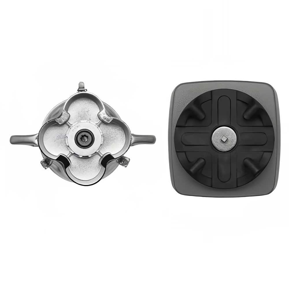
At the heart of the device lies a powerful motor assembly, which drives the machine’s blending functions. This motor is designed to handle heavy-duty tasks and provides the necessary force to power through tough ingredients like ice or dense mixtures. A durable motor also contributes to the longevity and reliability of the device.
Blades and Jar
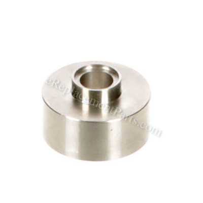
The blades, made from high-grade materials, are engineered for precision and efficiency. These sharp, sturdy blades rotate at high speeds, making them ideal for cutting through a wide range of ingredients. Paired with the robust jar, they work seamlessly to create consistent textures, whether you’re blending liquids or solid
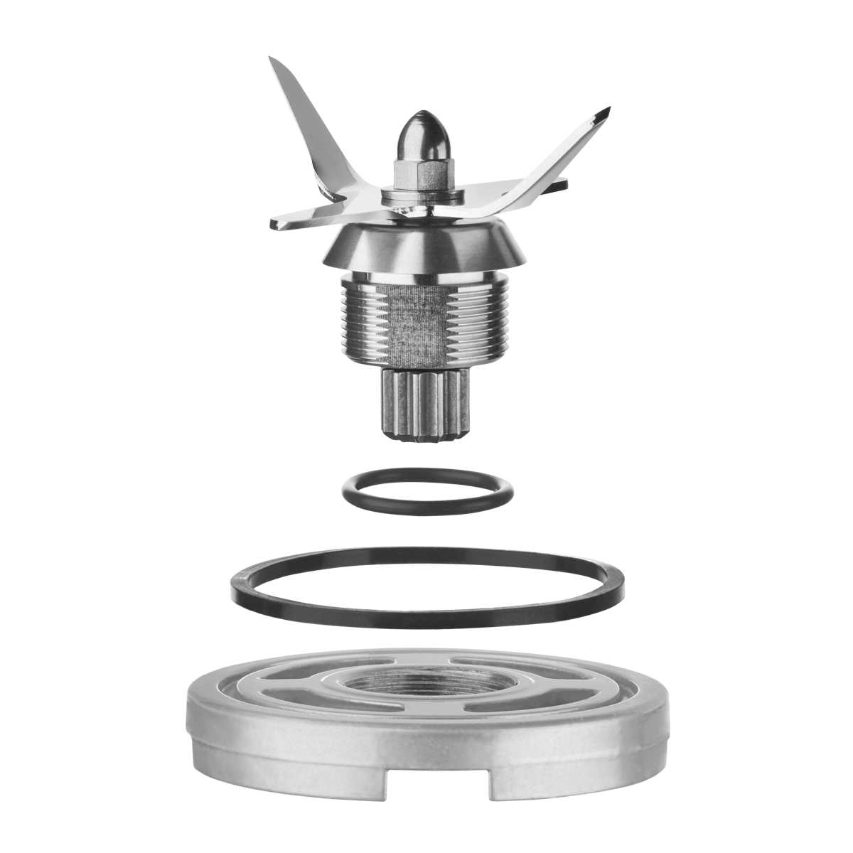
Blade Mechanism Breakdown for Waring CB15
The cutting system plays a crucial role in ensuring smooth and efficient blending operations. Understanding the various components and how they work together will help in maintaining performance and extending the lifespan of the appliance.
Main Components
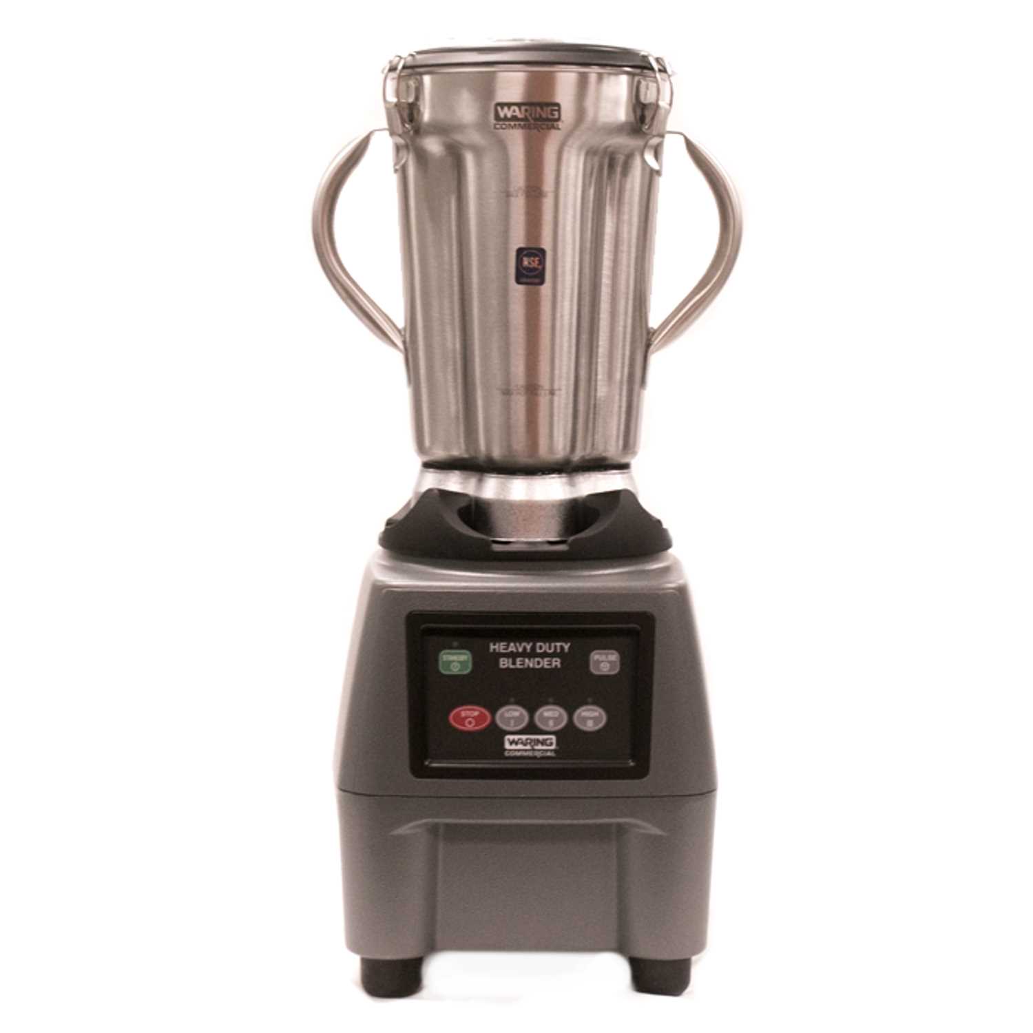
- Rotating blades: These are the core of the blending process, designed to handle a variety of ingredients.
- Blade assembly base: This section holds the blades securely in place while ensuring stability during operation.
- Seals and gaskets: These parts prevent leaks and keep the mechanism running smoothly by protecting it from liquid exposure.
How It Works
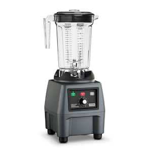
- The motor engages with the blade system, initiating a powerful spinning action.
- The sharp edges slice through the ingredients, breaking them down effectively
Motor System Overview in the Waring CB15
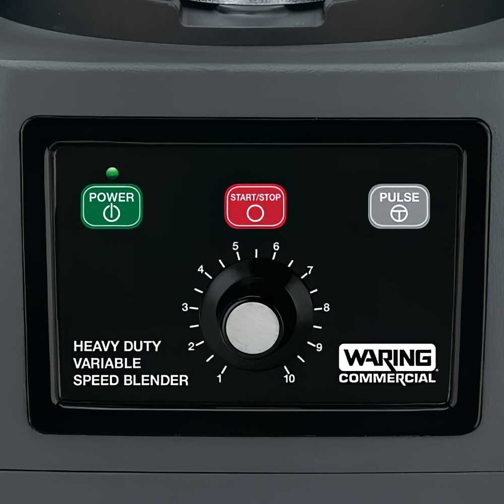
This section provides a comprehensive look at the driving mechanism within the specific appliance. Understanding this component is crucial for grasping its operational efficiency and reliability.
The motor system plays a vital role in the appliance’s functionality. Here are some key aspects:
- Type of Motor: The driving unit typically utilizes a powerful electric motor designed for continuous operation.
- Power Output: It is engineered to deliver a significant amount of torque, facilitating efficient blending and mixing.
- Speed Variability: The mechanism often features adjustable speed settings, allowing for versatility in food preparation tasks.
In addition, maintenance and care are essential to ensure longevity:
- Regularly inspect the motor for signs of wear and tear.
- Keep the motor clean and free from debris to maintain performance.
- Follow manufacturer guidelines for servicing to prevent issues.
By understanding these elements, users can maximize the effectiveness of their appliance and ensure optimal performance over time.
Exploring the Waring CB15 Jar Design

The design of the blending container is crucial for achieving optimal performance and efficiency in food preparation. This section delves into the key features and innovative aspects of the container used in commercial blending appliances.
The jar is crafted to ensure durability while maintaining a lightweight feel, making it easy to handle during operation. Its shape promotes effective blending, allowing ingredients to circulate seamlessly for uniform consistency.
Feature Description Material High-quality, impact-resistant material Capacity Generous volume suitable for large batches Design Ergonomic handle for comfortable pouring Compatibility Designed to fit securely with the base unit The combination of these elements enhances the overall user experience, making the blending process more efficient and enjoyable. Such thoughtful design contributes significantly to the appliance’s functionality, catering to both professional and home chefs alike.
Control Panel Layout of the Waring CB15
The control interface of this appliance is designed for user-friendly operation, ensuring that every function is easily accessible. Understanding the arrangement of controls can enhance the overall experience, allowing for efficient and effective use.
Main Controls Overview
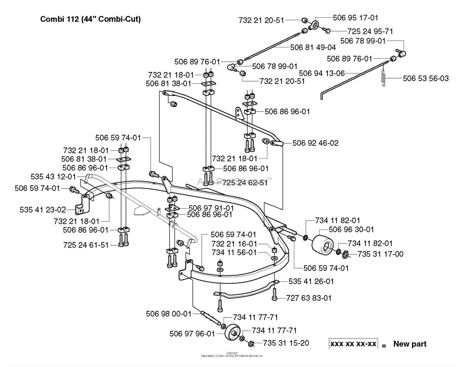
- Power Switch: This button activates the device, providing an easy way to start operations.
- Speed Settings: A dial or buttons that adjust the blending speed, allowing for customization based on the desired texture.
- Pulse Feature: A function that provides short bursts of operation for precise blending control.
Additional Features
- Indicator Lights: These lights inform the user of the device’s operational status.
- Timer Setting: An option to set specific blending durations for consistent results.
How the Waring CB15 Lid Works
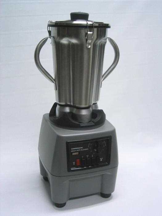
The lid of this blending device plays a crucial role in ensuring proper operation and safety during use. It serves as a protective barrier, preventing contents from spilling while the machine is in motion. Its design allows for secure closure, which is essential for effective blending.
One of the key features of the lid is its fit, which creates an airtight seal. This not only helps maintain the consistency of the ingredients but also reduces noise levels during operation. The lid is crafted to withstand high-speed blending, ensuring durability and longevity.
Additionally, many models incorporate a removable center plug. This feature provides the flexibility to add ingredients while the device is in use, allowing for a seamless blending experience. The design focuses on user convenience and efficiency, making it an integral part of the blending process.
Base Structure of the Waring CB15 Blender

The foundational framework of this blending device plays a crucial role in its overall functionality and durability. It is designed to provide stability while accommodating various components essential for blending tasks. This structure ensures that the appliance operates efficiently, minimizing vibrations and maintaining balance during use.
Maintaining the Sealing Gaskets in Waring CB15
Proper upkeep of the sealing components is crucial for optimal performance and longevity of your equipment. These gaskets play a significant role in preventing leaks and maintaining efficiency during operation.
To ensure the sealing elements remain effective, consider the following maintenance tips:
- Regular Inspection: Check for signs of wear, cracks, or deformation. Early detection can prevent larger issues.
- Cleaning: Keep the gaskets free from debris and residue. Use a mild detergent and soft cloth for cleaning.
- Replacement: If damage is evident, replace the gaskets promptly. Ensure you use compatible replacements for best results.
- Proper Storage: When not in use, store the equipment in a dry, cool place to prevent degradation of the sealing materials.
By adhering to these maintenance practices, you can prolong the lifespan of your sealing components and ensure your machine operates smoothly and efficiently.
Drive Coupling System in Waring CB15
The drive coupling mechanism plays a crucial role in ensuring efficient power transmission between the motor and the operational components. This system is designed to facilitate smooth interaction, minimizing energy loss while maintaining optimal performance during use.
Components of the Drive Coupling Mechanism
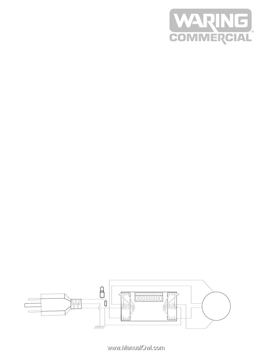
This system typically consists of several key elements that work in unison. Each component contributes to the overall functionality, ensuring durability and reliability in various applications.
Component Description Coupling Hub The central part that connects to the motor shaft. Drive Shaft Transmits power from the coupling hub to the blades. Isolation Ring Reduces vibration and noise during operation. Benefits of a Well-Designed System
A well-engineered coupling system enhances efficiency, reduces wear and tear, and prolongs the lifespan of the equipment. It allows for seamless operation, ensuring that the device meets the demands of various tasks effectively.
Electrical Wiring Insights for Waring CB15
Understanding the electrical connections in kitchen appliances is crucial for ensuring optimal performance and safety. This section explores the essential aspects of wiring arrangements, focusing on their significance in maintaining efficient operation.
Proper Wiring Techniques play a vital role in preventing issues such as short circuits and overheating. Ensuring that each connection is secure and appropriately insulated helps to avoid potential hazards during use.
Maintenance and Troubleshooting can greatly benefit from familiarizing oneself with the electrical layout. Recognizing common issues related to wiring can facilitate quicker repairs and enhance the longevity of the device.
Replacing the Power Switch in Waring CB15
Changing the electrical control mechanism in your appliance can enhance its functionality and ensure safe operation. This guide will provide a clear overview of the process, allowing you to successfully complete the task with minimal effort.
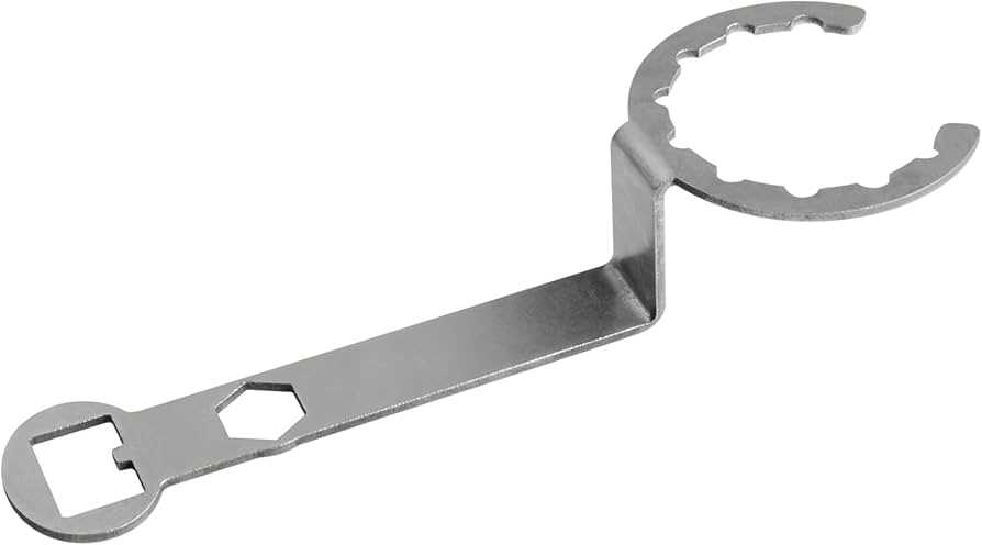
Necessary Tools and Materials
- Replacement switch
- Screwdriver set
- Multimeter
- Wire strippers
- Electrical tape
Steps for Replacement
- Unplug the appliance to ensure safety during the replacement process.
- Remove the outer casing using the appropriate screwdriver, exposing the internal components.
- Locate the existing control mechanism and disconnect any attached wires carefully.
- Install the new switch by connecting the wires according to the original configuration.
- Secure the outer casing back in place, ensuring all screws are tightened.
- Plug in the appliance and test the new control to verify proper operation.