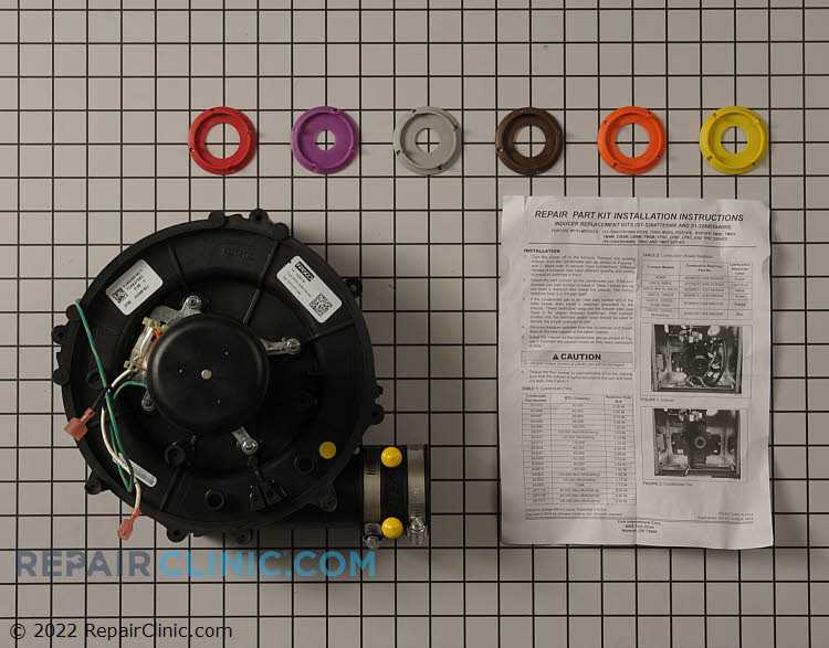
When working with heating and cooling systems, having a clear visual representation of their components is essential for efficient maintenance and troubleshooting. These illustrations serve as valuable references, guiding technicians through the intricate workings of the equipment.
Comprehending the arrangement of various elements can significantly enhance the diagnostic process. By familiarizing oneself with the configuration, professionals can quickly identify potential issues, streamline repairs, and ensure optimal performance of the machinery.
In this section, we will explore the significance of these visual guides, emphasizing their role in effective system management. Understanding how different components interact can lead to better decision-making and improved operational efficiency.
Understanding York Parts Diagram Basics
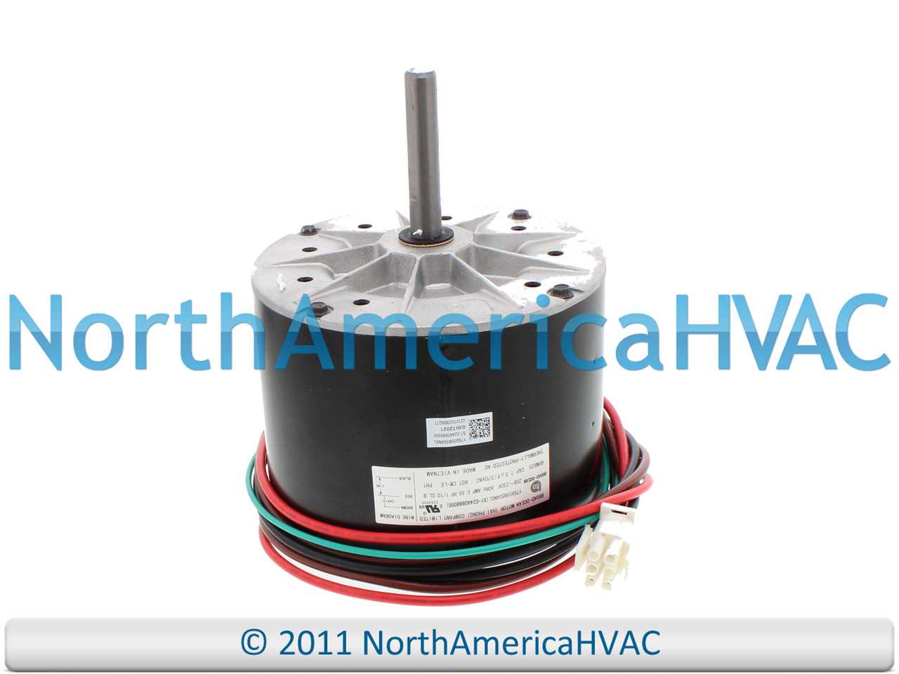
This section aims to provide an overview of the essential elements that contribute to the effective functioning of complex systems. By breaking down components and their interactions, users can better comprehend how these systems operate. A visual representation serves as a valuable tool for identifying individual elements and understanding their roles within the larger structure.
Key Components and Their Functions
- Elements: Each piece plays a crucial role in ensuring the system runs smoothly. Familiarity with these pieces allows for easier troubleshooting and maintenance.
- Connections: Understanding how components link to one another helps in grasping the flow of operation. This insight is vital for identifying potential issues.
- Labels: Clear identifiers are essential for recognizing each element’s purpose. Proper labeling aids in efficient navigation of the visual representation.
Benefits of Familiarization
- Enhanced Troubleshooting: Knowing how elements interact allows for quicker diagnosis of issues.
- Improved Maintenance: Regular checks can be performed more effectively when one understands the layout and function of each component.
- Informed Upgrades: Recognizing which pieces can be enhanced or replaced helps in making better decisions for system improvements.
Importance of Accurate Diagrams
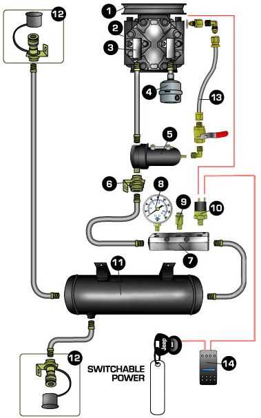
Precise illustrations play a crucial role in various fields, serving as visual aids that facilitate understanding and communication. When details are represented accurately, it allows users to comprehend complex systems more effectively, leading to improved functionality and maintenance.
Clarity is essential when conveying information, as any misrepresentation can result in confusion and mistakes. Well-crafted visuals not only enhance the learning experience but also ensure that individuals can navigate through intricate components without difficulty. Furthermore, these representations support efficient troubleshooting, enabling quick identification of issues and reducing downtime.
In summary, reliable illustrations contribute significantly to the successful operation of machinery and systems. By investing in high-quality visuals, users can enhance their understanding, streamline repairs, and ultimately improve the longevity of their equipment.
Key Components in York Systems
Understanding the essential elements within these systems is crucial for effective operation and maintenance. Each component plays a vital role, contributing to the overall efficiency and functionality of the units. This section explores the primary features found in these systems, highlighting their importance and interconnections.
Essential Elements
Among the core elements are the compressors, which are responsible for the refrigeration cycle, enabling the cooling process. These units also include condensers, crucial for dissipating heat, and evaporators, where the refrigerant absorbs heat to provide cooling. Each part must work in harmony to ensure optimal performance and energy efficiency.
Control Mechanisms
Effective management is facilitated by control systems that regulate temperature and operational settings. These mechanisms allow for precise adjustments, improving energy conservation and user comfort. Incorporating advanced technologies, such as programmable thermostats, enhances the adaptability of the units to varying environmental conditions.
Common Issues with York Parts
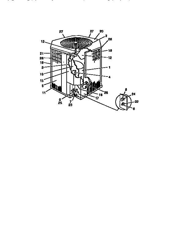
When dealing with components in heating and cooling systems, several recurring challenges may arise, impacting overall functionality and efficiency. Understanding these potential pitfalls is essential for maintenance and troubleshooting, ensuring optimal performance in any setup. From wear and tear to compatibility issues, addressing these concerns promptly can prolong the lifespan of the equipment.
Wear and Tear
Over time, mechanical components can experience degradation due to continuous use. This wear can lead to decreased efficiency and potential failures. Regular inspections and timely replacements of worn-out elements are crucial for maintaining reliable operation and preventing further damage.
Compatibility Concerns
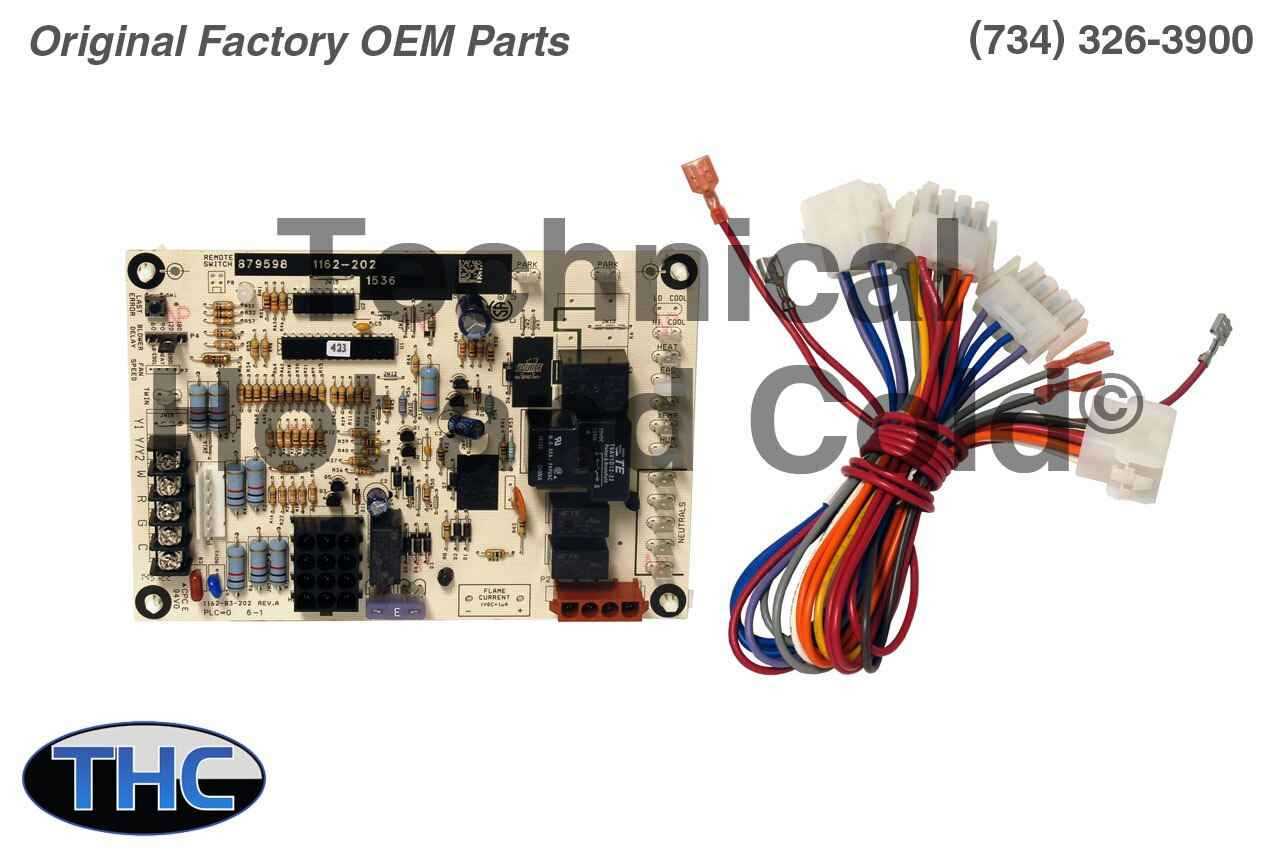
Integrating various components from different manufacturers may result in compatibility issues. Mismatched specifications can lead to improper functioning and inefficiencies. It is vital to verify that all elements are compatible and adhere to the required standards to ensure seamless operation.
Identifying Components by Diagrams
Understanding the layout of mechanical assemblies is essential for effective maintenance and repair. Visual representations serve as valuable tools for recognizing various elements within a system, enabling users to pinpoint specific items and their relationships. These illustrations facilitate a clearer grasp of intricate configurations, streamlining troubleshooting processes.
Each component in a schematic is typically labeled with unique identifiers, allowing for straightforward navigation and reference. This organized approach aids technicians in quickly locating necessary parts, ensuring that repairs are executed efficiently. Moreover, familiarization with these visuals empowers users to interpret information effectively, ultimately enhancing their problem-solving skills.
Utilizing such visual guides not only simplifies the identification process but also supports informed decision-making during maintenance tasks. By relying on these representations, individuals can maintain the integrity of their systems while minimizing downtime and preventing potential issues. Thus, mastering the interpretation of visual aids is a crucial aspect of proficient technical support.
Maintenance Tips for York Equipment
Regular upkeep is essential for ensuring the longevity and efficiency of your machinery. Adopting a proactive approach to maintenance can prevent unexpected breakdowns and costly repairs. Understanding key components and implementing routine checks can enhance the performance of your devices.
1. Schedule Routine Inspections: Conducting regular evaluations of the equipment helps identify potential issues before they escalate. Look for signs of wear and tear, and ensure that all components are functioning as intended. Maintaining a schedule for these inspections is crucial for optimal performance.
2. Keep Components Clean: Dirt and debris can accumulate over time, leading to inefficient operation. Regularly clean all accessible parts, ensuring that air filters, coils, and vents are free from obstruction. This simple task can significantly improve airflow and cooling efficiency.
3. Monitor Fluid Levels: Adequate lubrication is vital for the smooth operation of machinery. Regularly check and replenish oils and refrigerants as needed. Insufficient fluid levels can result in overheating and decreased efficiency.
4. Invest in Quality Replacement Components: When replacements are necessary, choosing high-quality components ensures compatibility and longevity. Avoiding substandard alternatives can prevent further issues down the line.
5. Stay Informed: Keep up with the latest maintenance practices and manufacturer recommendations. Resources such as manuals and online guides provide valuable information on how to properly care for your equipment.
How to Read a York Diagram
Understanding a schematic representation is essential for anyone working with mechanical systems. These visual guides provide crucial information about the components and their interconnections. By mastering how to interpret these visuals, you can troubleshoot issues, perform maintenance, or upgrade systems effectively.
To effectively decipher a visual representation, start by familiarizing yourself with the symbols and notations used within the image. Each component typically has a specific icon or abbreviation, making it easier to identify its function. Below is a brief overview of common elements you may encounter:
| Symbol/Notation | Description |
|---|---|
| Circle | Represents a circular component, such as a valve or motor. |
| Arrow | Indicates the direction of fluid flow or electrical current. |
| Rectangle | Signifies a rectangular component, often used for control panels or filters. |
| Dashed Line | Denotes a connection that is not physically present, such as a control signal. |
Once you understand the symbols, examine the layout carefully. Look for connections and pathways that show how different components interact. Pay attention to any notes or labels that may clarify the function of specific elements. This approach will enhance your ability to navigate the visual guide efficiently.
Parts Replacement: Step-by-Step Guide
Replacing components in your equipment can enhance its performance and extend its lifespan. This guide will walk you through the essential steps to ensure a smooth and efficient replacement process, helping you maintain optimal functionality.
Preparation
Before diving into the replacement process, gather all necessary tools and new components. Consult the manufacturer’s manual to familiarize yourself with the specific elements that require attention. Make sure to disconnect power sources and take safety precautions to prevent accidents.
Replacement Process
Start by removing the faulty component carefully. Take note of how it is installed to ensure proper placement of the new piece. Once removed, install the replacement by reversing the removal steps. Make sure all connections are secure and components are properly aligned. After everything is in place, restore power and conduct a thorough test to confirm successful operation.
By following these straightforward steps, you can efficiently replace components and maintain the reliability of your system.
Tools Needed for York Maintenance
Proper upkeep of equipment is essential for optimal performance and longevity. Having the right instruments on hand not only simplifies the maintenance process but also ensures that tasks are completed efficiently and effectively. This section outlines the essential tools that are indispensable for any maintenance routine.
First and foremost, a reliable set of wrenches is crucial for loosening and tightening various components. Additionally, screwdrivers in multiple sizes and types are necessary for accessing different screws and fasteners. A quality multimeter is essential for electrical diagnostics, allowing for accurate troubleshooting of electrical issues.
Furthermore, pliers, both standard and needle-nose, provide versatility for gripping and bending tasks. A torque wrench ensures that bolts are tightened to the manufacturer’s specifications, preventing damage from overtightening. Lastly, safety gear, such as gloves and goggles, is vital to protect the technician during maintenance activities.
Comparing York Models and Diagrams
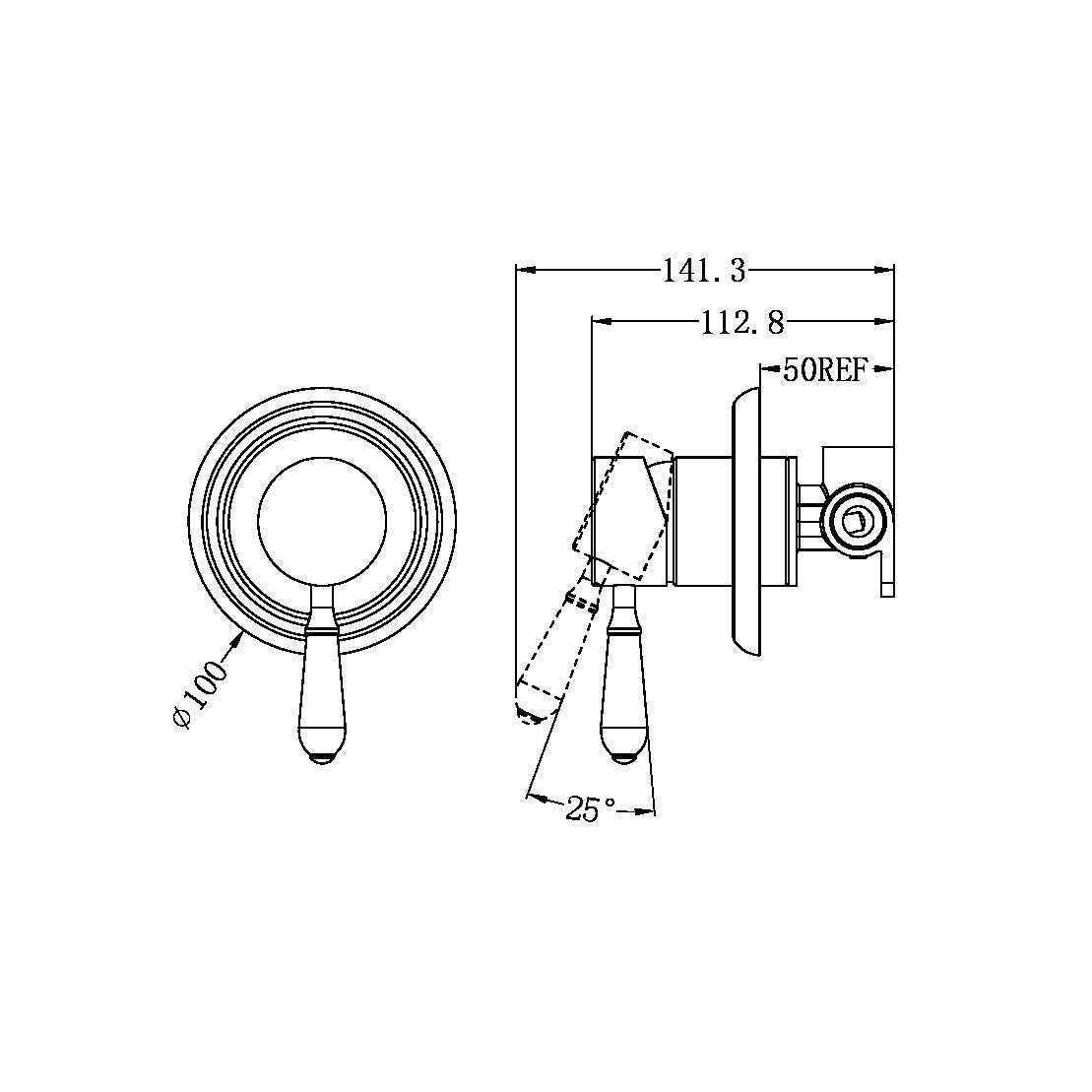
This section explores the various models and their corresponding schematics, highlighting the differences and similarities that can influence maintenance and troubleshooting. Understanding these variations is essential for optimizing performance and ensuring efficient operation.
Key Features of Different Models
- Design specifications that vary by model
- Component layouts and accessibility
- Efficiency ratings and energy consumption
- Control systems and technology integration
Interpreting the Schematics
Understanding the representations of various units involves analyzing how components are arranged and function together. Here are some crucial elements to consider:
- Identification of critical components
- Flow of energy and refrigerants
- Connection points for maintenance and service
- Potential troubleshooting indicators
By examining these aspects, users can better navigate the complexities of their systems, ensuring effective operation and longevity.
Exploring York’s Parts Catalog
This section delves into a comprehensive resource that offers a detailed overview of various components essential for maintaining efficiency in equipment. Users can navigate through an extensive compilation designed to enhance understanding and accessibility to crucial items.
Understanding the Catalog: The catalog serves as an ultimate guide, presenting organized listings that facilitate the identification and procurement of necessary elements. Each entry is meticulously detailed, providing specifications and compatibility information.
Utilizing the Resource: Engaging with this resource empowers users to make informed decisions regarding repairs and upgrades. By familiarizing themselves with available options, individuals can optimize performance and longevity of their systems.
Diagnosing Problems Using Diagrams
Understanding complex systems can be a daunting task, especially when troubleshooting issues. Visual representations can serve as invaluable tools for identifying and addressing malfunctions. By mapping out the components and their interrelations, one can quickly pinpoint potential trouble areas, leading to more efficient resolutions.
Utilizing these visual aids allows for a structured approach to diagnostics. When faced with an anomaly, consulting a visual guide can streamline the troubleshooting process by providing a clear overview of the system’s architecture. This can significantly reduce the time spent on identifying the root cause of the problem.
| Step | Description |
|---|---|
| 1 | Review the visual aid to understand the layout and connections. |
| 2 | Identify symptoms of the issue at hand. |
| 3 | Trace the relevant components using the visual representation. |
| 4 | Isolate potential faults based on the connections and functions. |
| 5 | Implement corrective measures based on identified issues. |
Employing visual schematics not only enhances comprehension but also fosters a systematic methodology. This approach ensures that all aspects are considered, reducing the likelihood of oversight and facilitating a thorough examination of the system in question.
Resources for York Parts Information
Accessing accurate and detailed information about components is essential for effective maintenance and repair. A variety of resources are available to help individuals locate specifications, compatibility details, and troubleshooting guides that facilitate informed decisions.
Online Databases
Numerous online repositories provide extensive catalogs and technical documents. These platforms often feature user-friendly interfaces that allow for quick searches and downloads.
Community Forums
Engaging with fellow enthusiasts through community discussions can yield valuable insights. These platforms foster knowledge sharing and practical advice based on real-world experiences.
| Resource Type | Examples |
|---|---|
| Online Catalogs | Manufacturer websites, third-party retailers |
| Forums | Dedicated discussion boards, social media groups |
| Technical Support | Help centers, customer service |