| Component |
Main Functions of Submersible Well Pumps
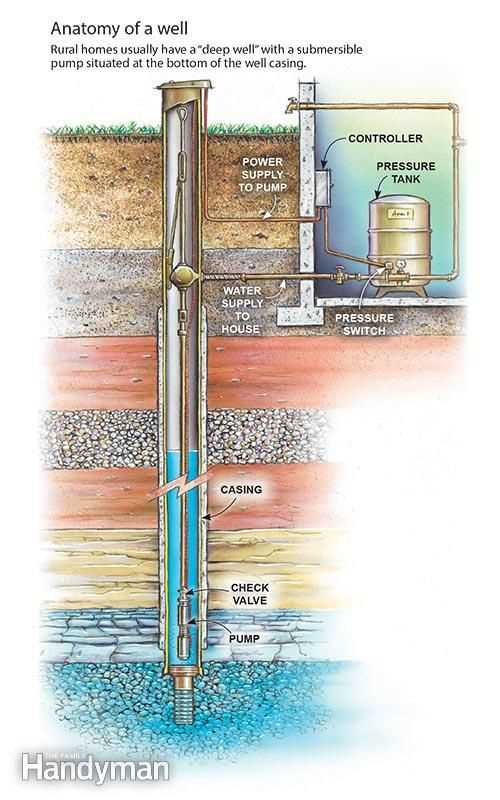
The primary purpose of deep-water extraction devices is to transport liquids from significant depths to the surface. These systems are designed to operate efficiently in challenging environments, where they ensure a continuous flow of liquid while minimizing energy consumption and wear on the mechanism. Their performance is crucial for maintaining a reliable water supply in various applications.
Key Operations
- Efficient fluid transport from underground sources to designated areas.
- Maintaining steady pressure throughout the entire fluid distribution network.
- Ensuring energy-efficient operation while handling large volumes of liquid over extended periods.
Support for Various Applications
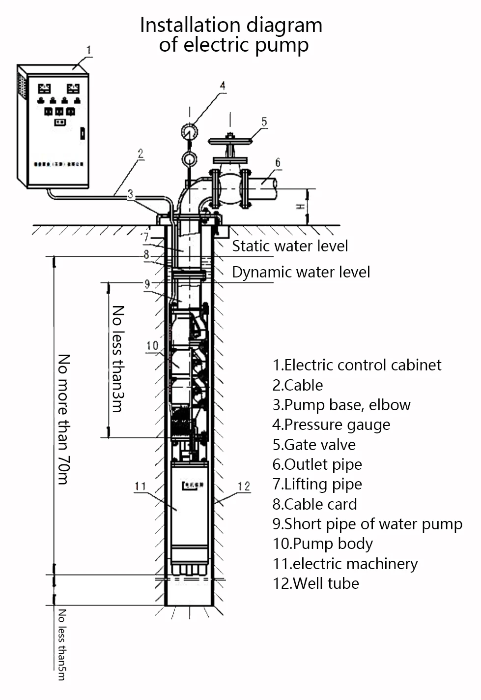
These systems are versatile, catering to a wide range of uses, from residential to industrial needs. Their robust construction allows them to handle different types of fluids, including those that may contain small amounts of sediment or impurities.
Identifying Key Parts of a Well Pump
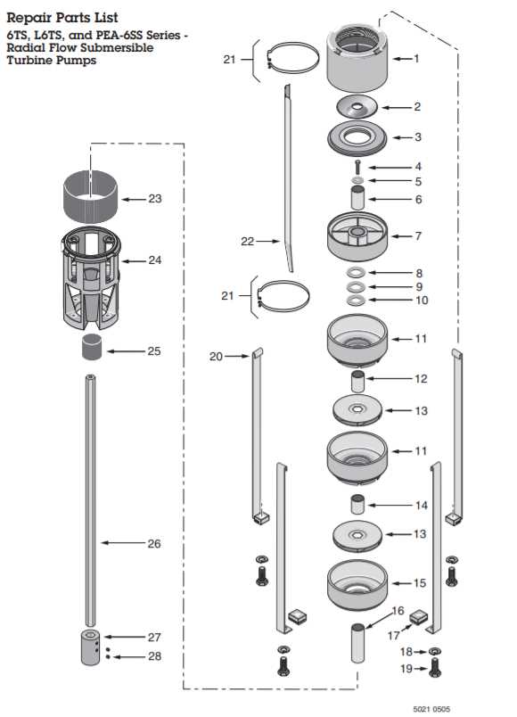
Understanding the essential components of water extraction devices is crucial for efficient maintenance and operation. These devices are made up of various elements that work together to move liquid from underground sources to the surface. By familiarizing yourself with the key features, you can more easily diagnose issues and ensure proper functionality.
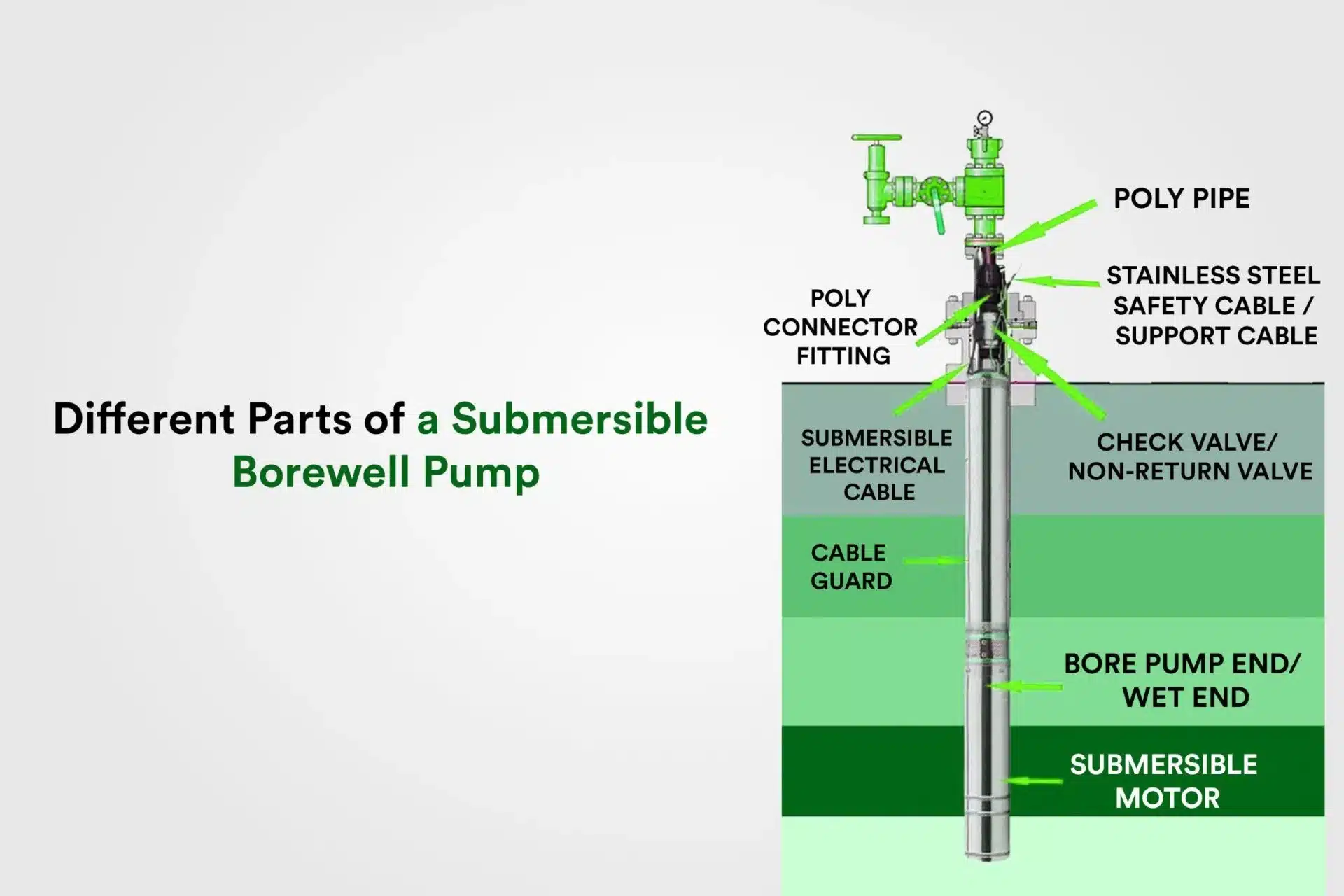
Motor: The driving force behind the operation, this element converts electrical energy into mechanical motion. It powers the entire system, ensuring that liquid can be transferred effectively.
Impeller: This rotating mechanism plays a vital role in creating the necessary pressure to move liquid through the system. Its design allows for smooth and consistent flow.
Shaft: Connecting various parts together, the shaft transmits the motor’s power to the impeller, ensuring that all components work in harmony.
How the Motor Drives Water Movement
The motor’s role in creating fluid motion is central to the operation of various systems designed to transport liquids. By converting electrical energy into mechanical force, the motor generates the necessary power to move water efficiently through the system.
At the heart of this process is the rotor, which spins as electrical current flows through the motor’s components. This rotational movement transfers energy to a shaft, which in turn activates a set of blades or an impeller. These rotating elements push the water forward, increasing pressure and directing the liquid flow upward or outward, depending on the system’s design.
The efficiency of this movement depends largely on the alignment and speed of the motor’s rotating parts. Proper calibration ensures smooth operation, preventing energy loss and maintaining a steady flow. As a result, water is driven effectively through the system with minimal effort, optimizing performance and reliability.
The Role of Impellers in Water Flow
Impellers play a critical role in generating the movement of liquid, transforming rotational energy into dynamic fluid motion. Their function is essential in maintaining consistent water circulation, allowing fluid to move efficiently through various channels.
How Impellers Create Movement
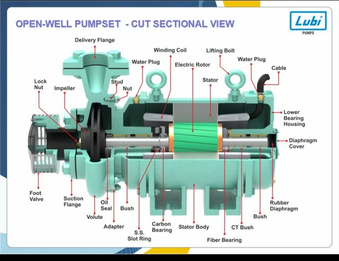
Impellers operate by rotating at high speeds, creating centrifugal force that propels water outward. This force increases the velocity of the water, driving it through different pathways. The design and material of the impeller directly impact the efficiency of this process.
- Blades: The curved or angled blades determine the direction and speed of the liquid flow.
- Material: Typically made from metals or durable plastics, the impeller’s material affects its durability and resistance to wear.
- Size and Shape: Larger or more intricately shaped impellers can move greater volumes of water or create higher pressure.
Types of Impellers and Their Effects
Different
Casing and Housing Structure Explained
The casing and housing play a crucial role in the functionality of various fluid transport systems. These components provide essential support and protection, ensuring optimal performance and longevity. Understanding their structure and purpose is key to comprehending the overall operation of such mechanisms.
The casing is typically a robust external structure designed to safeguard internal mechanisms from environmental factors, while the housing encapsulates specific components that facilitate fluid movement. Together, they form a seamless unit that prevents contamination and allows for efficient operation.
Materials used for casing and housing are often chosen for their durability and resistance to corrosion, ensuring that they can withstand harsh conditions. Design features, such as thickness and shape, are tailored to meet the specific requirements of each application, enhancing overall reliability.
Moreover, the integration of various elements within the casing and housing can influence efficiency. For instance, the alignment and spacing of internal components are critical for minimizing friction and maximizing flow rates. Proper maintenance of these structures is vital, as any degradation can lead to performance issues and increased operational costs.
In conclusion, the casing and housing are fundamental to the efficiency and effectiveness of fluid transport systems. Their design and materials significantly impact performance, highlighting the importance of understanding these essential components.
Importance of Check Valve in Pump Systems
A check valve plays a crucial role in fluid transport systems by ensuring the unidirectional flow of liquid. This device prevents backflow, which can lead to inefficiencies and potential damage to the entire system. By maintaining a consistent direction of movement, it helps to optimize performance and safeguard against various operational hazards.
One of the primary functions of a check valve is to protect the integrity of the equipment. When liquid flows in reverse, it can cause pressure surges that may harm various components. The inclusion of a check valve minimizes these risks, enhancing the reliability of the system. In addition, it aids in maintaining the desired pressure levels, which is essential for the effective operation of any fluid management system.
Furthermore, the check valve contributes to energy efficiency. By preventing backflow, it reduces the workload on the motor and other related components, leading to lower energy consumption. This not only saves costs but also extends the lifespan of the equipment, making it a valuable investment in any fluid transfer setup.
In summary, the significance of a check valve cannot be overstated. It is a fundamental element that ensures optimal functionality, protects equipment, and promotes energy savings in fluid transport systems.
Electrical Wiring and Safety Considerations
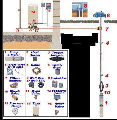
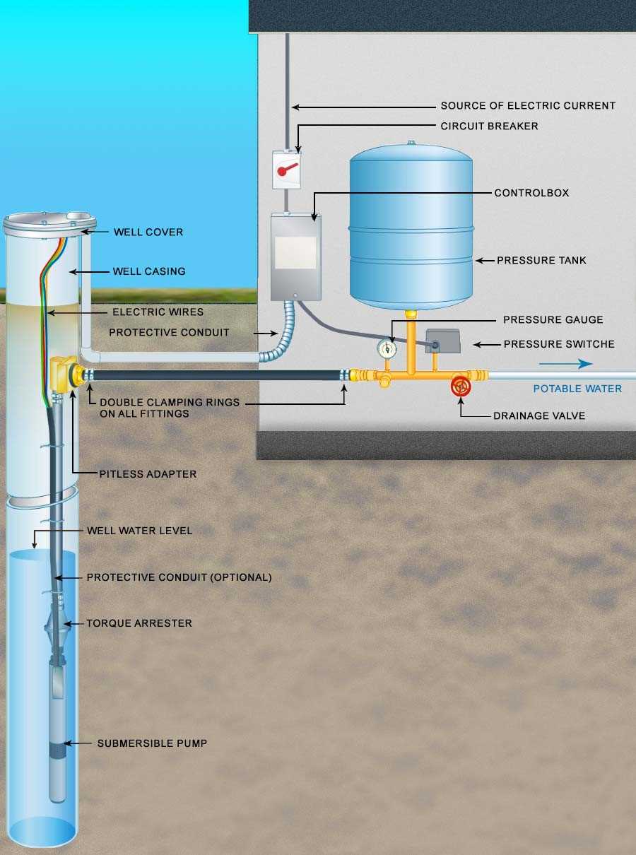
When working with devices designed for underwater installation, understanding the intricacies of electrical connections is crucial for both functionality and safety. Proper wiring ensures efficient operation and minimizes the risk of electrical hazards. It is essential to adhere to local regulations and manufacturer guidelines during installation and maintenance to prevent accidents and ensure longevity of the equipment.
Key Wiring Practices
Utilizing high-quality, corrosion-resistant materials is fundamental in environments exposed to moisture. All connections must be secured and protected against water ingress to avoid short circuits. Furthermore, implementing proper grounding techniques enhances safety, reducing the risk of electrical shock. Regular inspections and testing of electrical systems are also recommended to identify any wear or damage that may compromise safety.
Safety Precautions
Before commencing any electrical work, it is imperative to disconnect the power supply to the equipment. Utilizing personal protective equipment (PPE) such as insulated gloves and safety goggles can provide an extra layer of protection during installation or repairs. Additionally, employing circuit breakers or GFCI (Ground Fault Circuit Interrupter) devices offers an essential safeguard against potential electrical failures, ensuring a safe working environment.
Discharge Pipe and Water Delivery Path
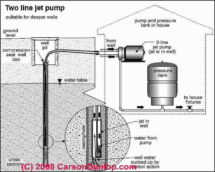
The discharge conduit plays a crucial role in transporting extracted fluid from its source to the desired location. Understanding this pathway is essential for ensuring efficient movement and optimal performance of the entire system. Various components work in unison to facilitate a smooth flow, minimizing potential losses and maximizing delivery effectiveness.
At the outset of the delivery process, the fluid exits through the discharge pipe, which is specifically designed to handle the pressure and volume of the transported liquid. This conduit must be constructed from durable materials to withstand environmental conditions and mechanical stresses. Proper installation and alignment are vital for preventing leaks and ensuring consistent flow.
The pathway then directs the fluid toward storage tanks or distribution systems, where it can be utilized for various applications. Throughout this journey, maintaining a clear and unobstructed route is essential to avoid blockages that could disrupt flow. Regular inspections and maintenance of the discharge components contribute to the longevity and reliability of the entire system.
In summary, the discharge pipe and the overall water delivery path are integral to the effective transportation of fluids. Understanding their design and function enables better planning and management of fluid extraction systems, ensuring efficient and reliable operation.
Shaft Seal and Protection Against Leaks
The integrity of mechanical systems is crucial for their efficient operation, especially in environments where fluids are handled. One of the essential components ensuring this integrity is the seal mechanism that prevents unwanted leakage. This segment focuses on the importance of seals in protecting the internal mechanisms from external contaminants and maintaining the system’s functionality.
Effective sealing solutions play a vital role in minimizing fluid loss and safeguarding the surrounding environment. These solutions are designed to withstand various pressures and temperatures, ensuring longevity and reliability. A well-designed sealing system can significantly reduce the risk of leaks, which may lead to costly repairs and environmental damage.
| Type of Seal |
Material |
Temperature Range |
Pressure Resistance |
| Mechanical Seal |
Ceramic, Carbon |
-40°C to 200°C |
Up to 20 bar |
| Rubber Gasket |
EPDM, Nitrile |
-30°C to 100°C |
Up to 10 bar |
| O-Ring |
Viton, Silicone |
-50°C to 150°C |
Up to 15 bar |
| Lip Seal |
Polyurethane, Neoprene |
-40°C to 120°C |
Up to 12 bar |
In summary, selecting the appropriate sealing technology is paramount for maintaining system efficiency and preventing leaks. Proper installation and regular maintenance of these components are essential practices for ensuring optimal performance and extending the lifespan of the equipment.
Thermal Overload Protection in Submersible Pumps
Thermal overload protection is a critical safety feature designed to prevent equipment damage due to excessive heat generation. This mechanism plays an essential role in maintaining operational efficiency and extending the lifespan of machinery used in various applications. By monitoring temperature levels and providing automatic shutdown capabilities, this system ensures that devices function within safe limits.
Importance of Thermal Protection
Overheating can lead to severe consequences, including:
- Reduced efficiency and performance degradation
- Potential component failure or breakdown
- Increased maintenance costs and downtime
- Safety hazards for operators and surrounding equipment
How Thermal Overload Systems Work
These protective systems typically employ sensors to continuously monitor temperature. When the detected temperature exceeds a predefined threshold, the following actions occur:
- The device automatically shuts down to prevent damage.
- A warning signal is triggered to alert operators of the issue.
- Once the temperature returns to a safe range, the system can be reset for operation.
By incorporating thermal overload protection, operators can enhance safety measures and promote longer operational lifetimes for their machinery.
Maintenance Tips for Pump Longevity
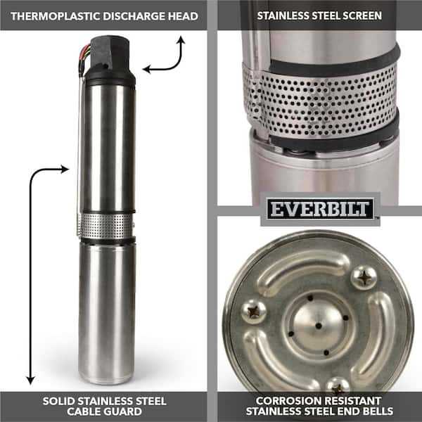
Ensuring the durability of your hydraulic equipment requires consistent care and attention. Regular maintenance practices can significantly extend the lifespan of the system and enhance its efficiency. This section provides essential guidelines to keep your equipment operating smoothly and reliably.
Regular Inspections
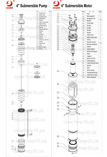
Performing frequent checks on the functionality of your machinery is crucial. Look for signs of wear, unusual noises, or vibrations during operation. Early detection of potential issues can prevent costly repairs and downtime.
Cleanliness is Key
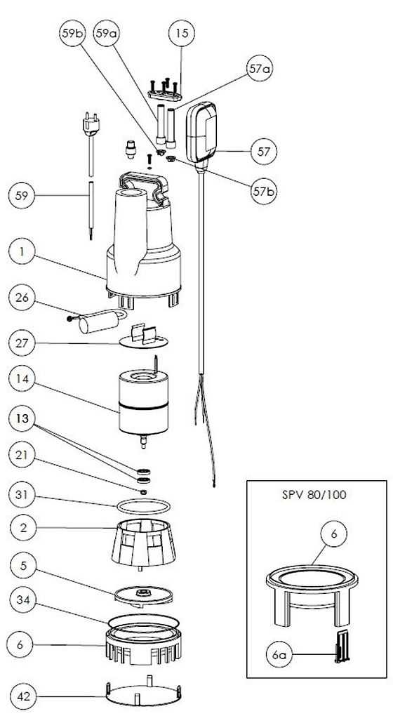
Keep the surrounding area clean and free from debris. Accumulated dirt can interfere with operation and cause damage over time. Regularly clean the equipment to ensure optimal performance. Additionally, inspect and clean any intake screens or filters as needed to maintain flow efficiency.
In conclusion, implementing these maintenance practices will help secure the longevity of your hydraulic system. Regular attention to detail and proactive measures will ensure reliable performance and reduce the risk of unexpected failures.
