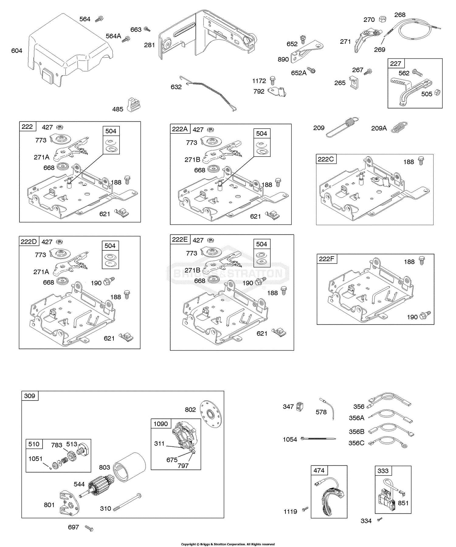
When it comes to maintaining outdoor equipment, understanding the essential elements that power the machinery is crucial. Every motorized device relies on specific mechanical pieces working in harmony to ensure efficiency and durability. By familiarizing yourself with the internal workings, you can gain valuable insights into how these devices operate and what is needed for proper upkeep.
Detailed examination of individual parts is vital for anyone looking to ensure the long-term functionality of their lawn equipment. Whether it is ensuring the smooth operation of key components or replacing worn-out elements, understanding the structure helps in identifying potential issues early. Clear knowledge of these elements is the first step toward efficient repair and maintenance.
In this guide, we will walk through the layout of various mechanical pieces within this type of engine. From critical operational components to supportive structures, each element plays a unique role in keeping the machine running smoothly. By the end, you will have a clearer picture of how all the components come together to
Understanding the Engine Model
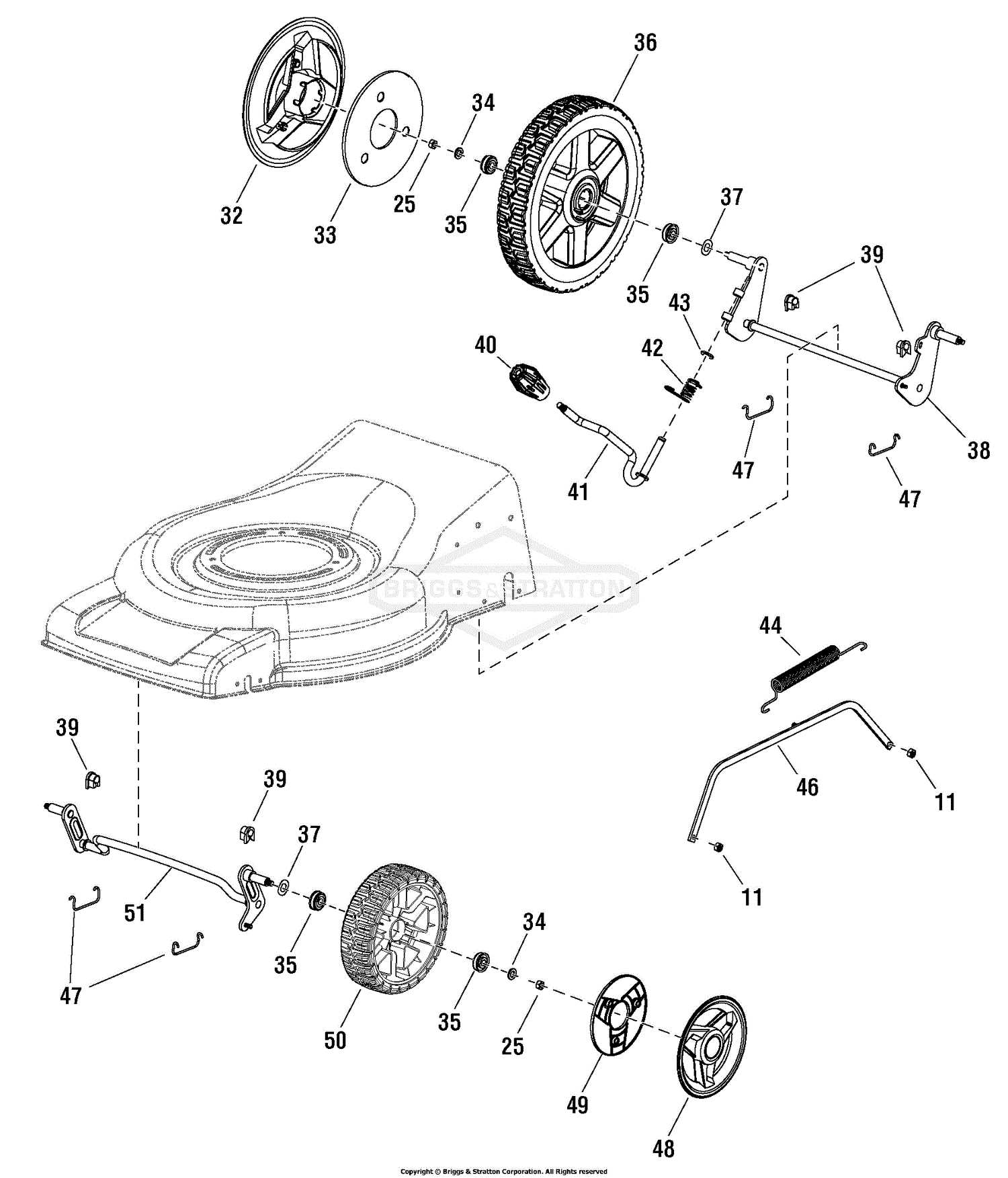
The internal workings of this popular engine type provide a solid foundation for many outdoor tools. With a focus on reliability and efficiency, this model is widely utilized in equipment designed for tasks such as lawn care. Its components are crafted to offer durability and ease of maintenance, making it a trusted option for various mechanical needs.
Key Features of the Engine
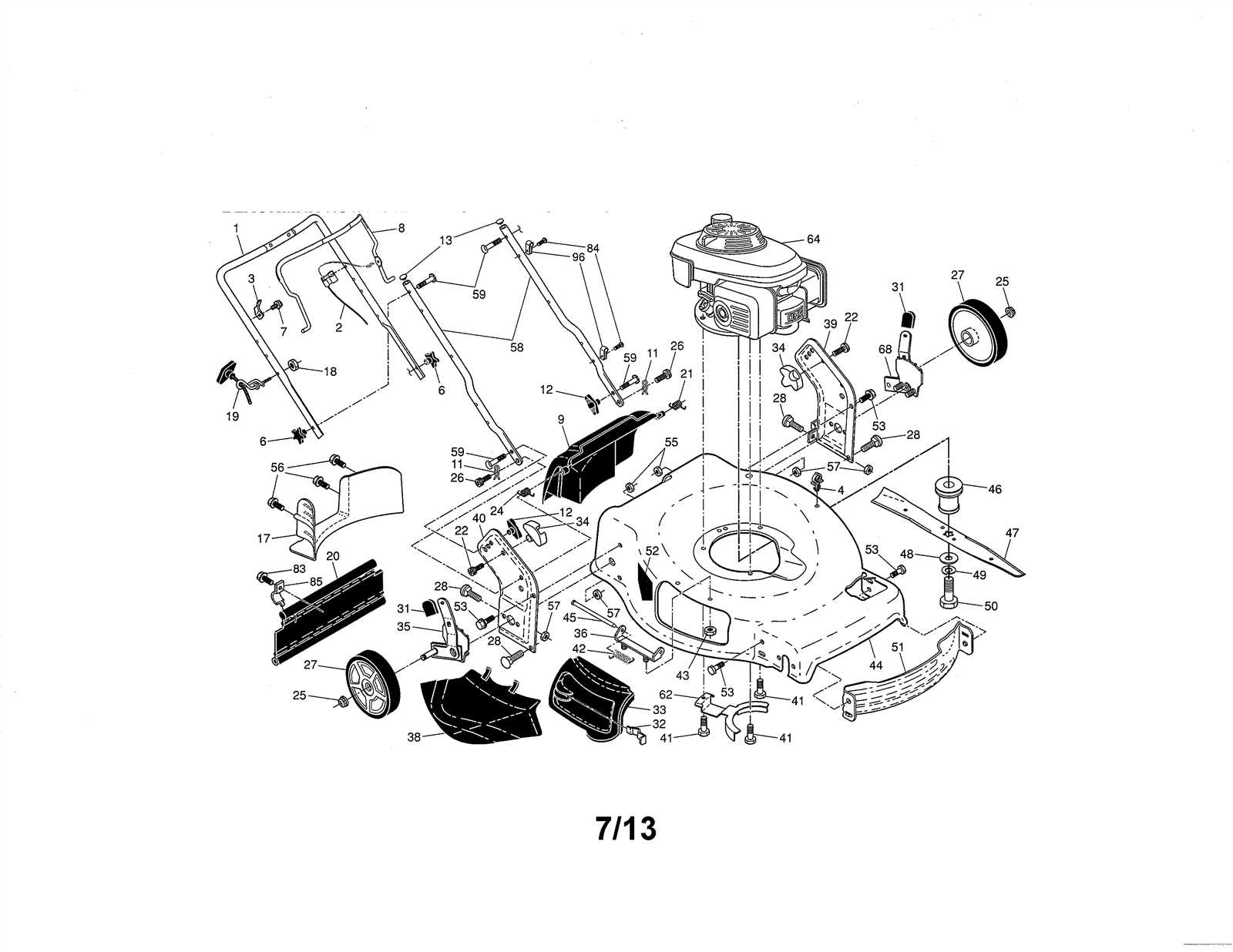
This engine model stands out for its efficient fuel consumption and straightforward maintenance. It includes a durable carburetor and an easy-to-use pull-start system, both contributing to its reliability. The engine’s lightweight build is a bonus, enhancing maneuverability without sacrificing power output.
Common Applications
This versatile engine powers a range
Key Components Overview
In this section, we will take a closer look at the fundamental elements that make up a typical engine system. These core components ensure smooth operation and efficient performance, each playing a vital role in the overall functionality of the machine.
Engine Block
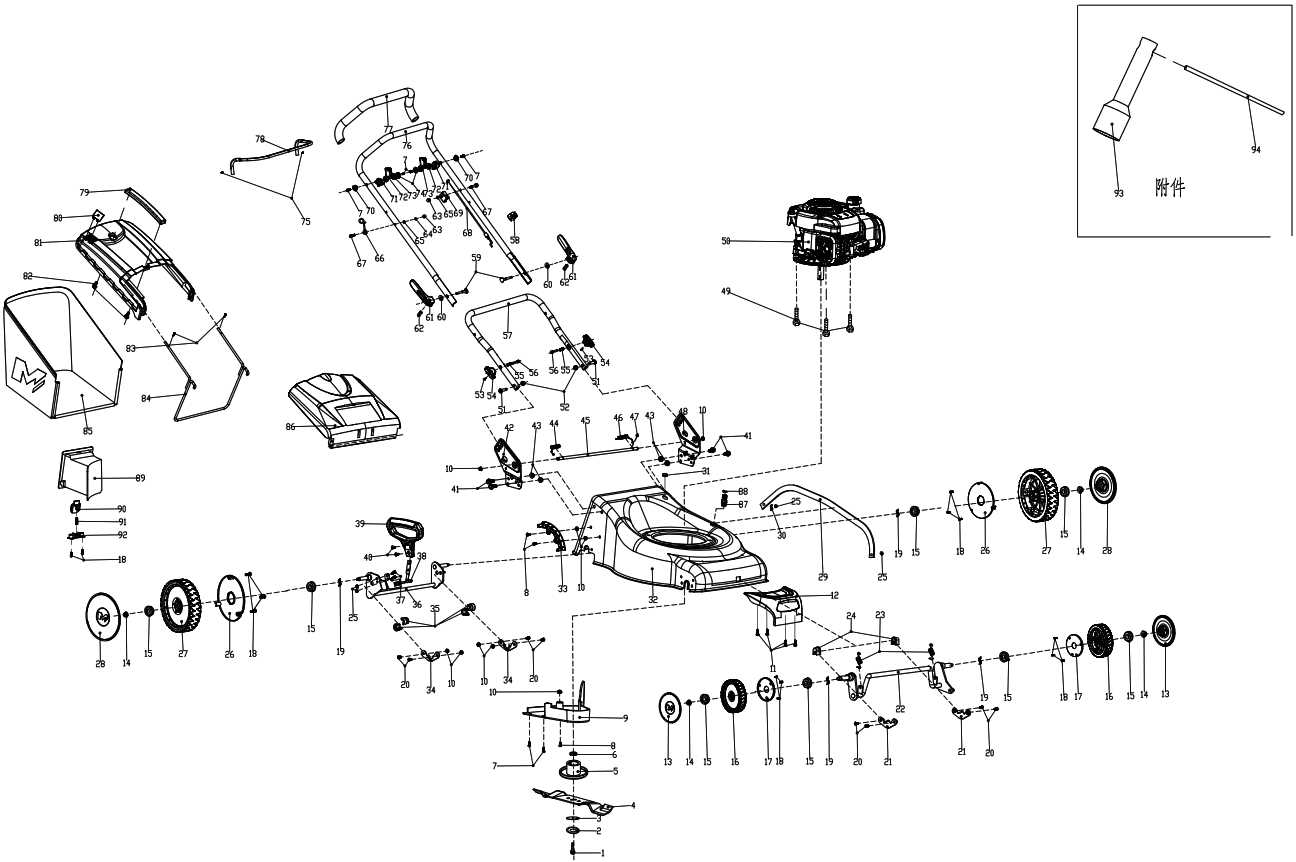
The foundation of the system, the engine block, houses critical mechanisms responsible for power generation. It supports the cylinders and provides a structure for all other connected elements.
- Supports mechanical components
- Acts as a frame for moving parts
- Ensures heat distribution and management
Ignition System
The ignition system is essential for starting the engine and maintaining consistent operation. It generates the necessary spark to ignite the fuel-air mixture within the cylinders.
- Spark plug
Engine Block Structure Breakdown
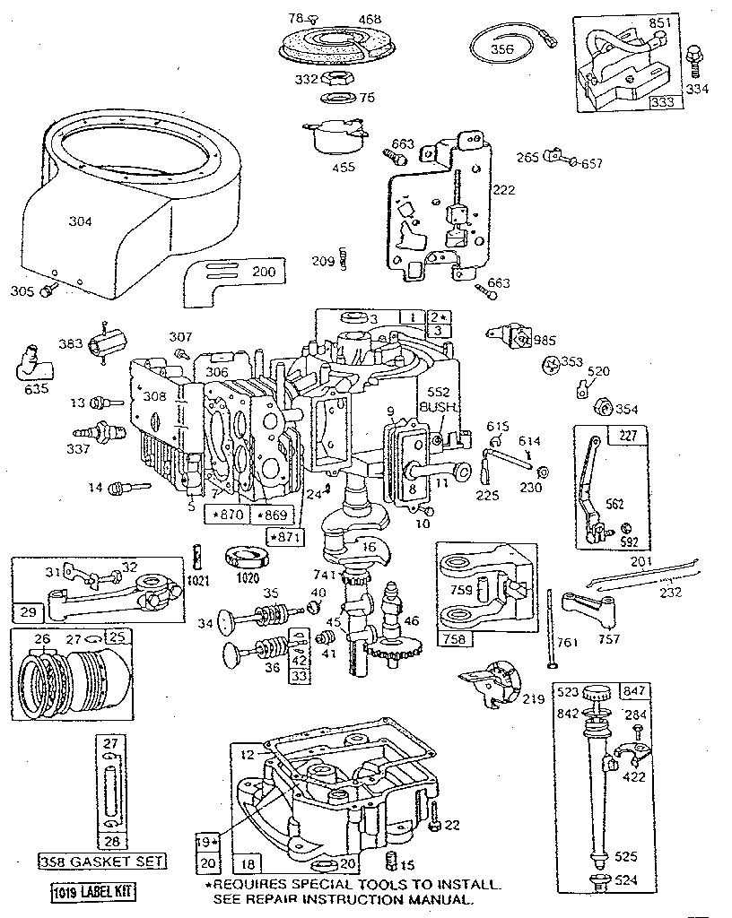
The internal framework of an engine block is critical to its overall functionality, providing both support and housing for essential components. Understanding its construction is key to maintaining and enhancing engine performance. This section covers the main structural elements, their purpose, and how they interact to ensure smooth operation.
- Cylinders: These form the core of the engine, housing the pistons. Proper alignment and material strength are crucial for compression and combustion processes.
- Crankcase: Located at the base, the crankcase houses the crankshaft and helps distribute lubrication. Its design ensures durability under high loads.
- Oil passages: Built into the block, these channels guide oil flow to critical areas, reducing friction and wear.
- Mounting points:
Fuel System Parts and Functions
The fuel system plays a vital role in ensuring proper engine performance by delivering the necessary fuel to the engine in a controlled and efficient manner. Each element within this system has a specific function, working together to maintain optimal combustion and power output. Understanding these components is essential for maintaining efficient engine operation and preventing common issues related to fuel delivery.
Fuel Tank: This component stores the liquid needed for engine operation. It is designed to keep the fuel safe from contamination and ensure a steady supply to the rest of the system.
Fuel Line: The line connects the storage area to the engine, ensuring the smooth transfer of fuel. It is made from durable materials to withstand pressure and prevent leaks.
Fuel Filter: Positioned along the line, this element is responsible for removing impurities before the fuel reaches the engine. A clean filter ensures efficient combustion and prolongs engine life.
Carburetor: This mechanism mixes air with fuel in the right proportions before sending it to the engine for combustion
Air Filter Assembly Configuration
The setup of the air filtration system is crucial for maintaining optimal engine performance. Properly arranged, it ensures that the engine receives clean airflow, preventing dust and debris from entering the combustion chamber. Below is a breakdown of the essential components involved in configuring the filter system.
- Filter Housing: The outer casing that securely holds the filter in place, protecting it from external elements.
- Filter Element: This component is responsible for trapping particles and ensuring only clean air passes through to the engine.
- Mounting Brackets: These are used to attach the filter housing to the engine, ensuring stability during operation.
- Seals and Gaskets: These prevent any unfiltered air from bypassing the filter element and entering the engine.
- Ensure the filter housing
Carburetor Design and Operation
The functionality of an air-fuel mixing device is critical for the efficient operation of various combustion engines. This component regulates the ratio of air and fuel that enters the engine, ensuring optimal performance under different operating conditions. A well-designed mechanism not only enhances efficiency but also contributes to smoother engine operation and reduced emissions.
Key Components and Their Roles
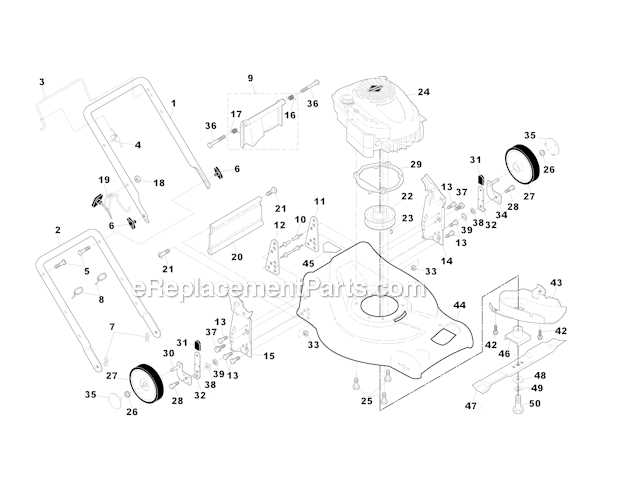
Within this device, several essential elements work together to achieve the desired air-fuel mixture. The throttle valve controls the flow of air, while the float chamber maintains a consistent fuel level. Additionally, the jet system delivers fuel at the appropriate rate based on engine demands. Each part must function harmoniously to maintain the ideal mixture, particularly during varying load conditions.
Operation Principles
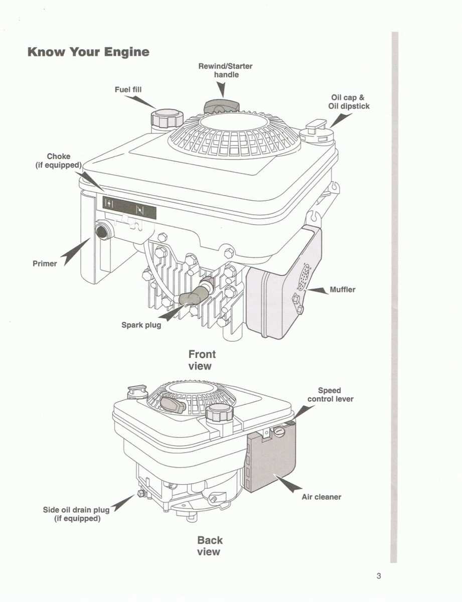
The operation of this system is based on principles of fluid dynamics. As air flows through the intake, its velocity increases, creating a drop in pressure that draws fuel from the chamber into the airstream. This process allows for precise control over the fuel delivery, adapting to the engine’s requirements as it accelerates or decelerates. Proper tuning of this system can lead to significant improvements in overall engine performance and fuel efficiency.
Ignition System Parts Overview

The ignition system plays a crucial role in the overall performance of small engines, ensuring that the combustion process occurs at the right time. This assembly is essential for starting the engine and maintaining its operation. Understanding the components involved can help in troubleshooting and maintaining optimal functionality.
Key Components
Each element within the ignition assembly has a specific function that contributes to the effective operation of the engine. Below is a brief overview of the main components found in typical ignition systems:
Component Description Coil Generates high voltage needed to ignite the fuel-air mixture. Flywheel Magnet Interacts with the coil to produce electrical current. Ignition Module Controls the timing of the spark and signals the coil to fire. Spark Plug Delivers the spark to ignite the air-fuel mixture in the combustion chamber. Maintenance Tips
Regular inspection and maintenance of the ignition components can enhance engine reliability and performance. Ensure that the connections are clean and secure, and replace any worn-out elements promptly. This proactive approach can prevent starting issues and ensure smooth operation.
Exhaust Components and Maintenance
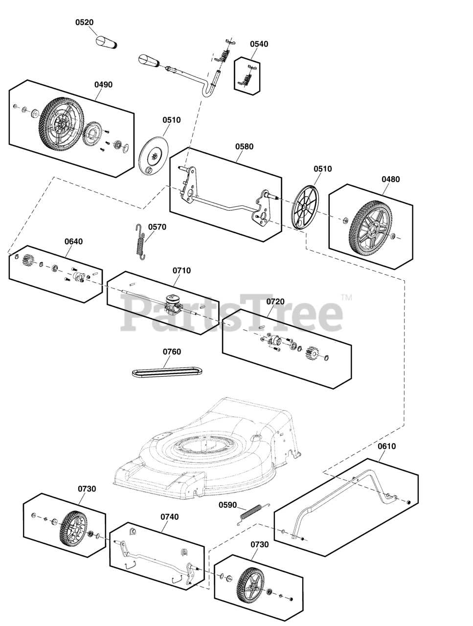
The exhaust system plays a crucial role in the efficient operation of small engines. Proper functioning of this system ensures that harmful gases are expelled safely while optimizing engine performance. Regular upkeep of exhaust components is essential for maintaining reliability and extending the lifespan of the equipment.
Key elements of the exhaust system include:
- Muffler: Reduces noise produced by the engine and directs exhaust gases away.
- Exhaust Pipe: Channels gases from the engine to the atmosphere, preventing backpressure that can hinder performance.
- Gaskets: Provide a seal between exhaust components, preventing leaks that can lead to inefficient operation.
- Heat Shield: Protects surrounding components from excessive heat generated by the exhaust.
To ensure optimal functionality, the following maintenance practices are recommended:
- Inspect all components for signs of wear or damage, especially gaskets and connections.
- Clean the muffler and exhaust pipe to remove any buildup that could restrict airflow.
- Check for leaks by examining joints and seams, and replace any damaged gaskets as needed.
- Ensure that the heat shield is intact and securely attached to prevent overheating of nearby parts.
By following these maintenance guidelines, users can help ensure that the exhaust system operates efficiently, contributing to the overall performance and durability of the engine.
Governor System Mechanism
The governor system plays a crucial role in regulating the speed of small engines. This mechanism ensures that the engine maintains a consistent speed, regardless of varying load conditions. By adjusting the fuel flow or throttle position, it helps optimize performance and efficiency, making it an essential component in the functioning of many power equipment engines.
Functionality of the Governor
This system operates by detecting changes in the engine’s speed. When the engine speed exceeds a predetermined level, the governor adjusts the throttle to reduce the power output, thereby stabilizing the engine’s operation. Conversely, if the engine slows down, the governor opens the throttle to increase power, ensuring smooth operation under different workloads.
Components of the Mechanism
The main components of a typical governor system include:
Component Description Weights These move outward as the engine speed increases, influencing the throttle position. Linkage Connects the weights to the throttle, allowing for adjustments based on speed. Spring Provides resistance to the weights, helping to determine the throttle’s response. Throttle Valve Regulates the air-fuel mixture entering the engine, controlled by the governor. Understanding the governor system mechanism is essential for effective maintenance and troubleshooting of engine performance issues. Regular inspection and adjustment of these components can lead to improved engine reliability and longevity.
Crankshaft and Piston Assembly Details
The connection between the crankshaft and piston assembly is a critical aspect of small engine functionality. This assembly is responsible for converting linear motion into rotational motion, enabling efficient power generation. Understanding the components involved and their interactions can enhance maintenance and troubleshooting efforts.
The crankshaft serves as the heart of the assembly, transforming the vertical movement of the piston into circular motion. Constructed from durable materials, it is designed to withstand significant forces during operation. The piston, on the other hand, is a cylindrical component that fits snugly within the engine cylinder. It moves up and down, creating the necessary pressure for combustion.
Proper alignment and fit of these elements are essential for optimal engine performance. The piston rings, which encircle the piston, play a vital role in sealing the combustion chamber, preventing gas leaks and ensuring efficient operation. Regular inspections and maintenance of the crankshaft and piston assembly can help identify wear and prevent costly repairs.
In summary, a thorough understanding of the crankshaft and piston assembly is crucial for effective engine maintenance. By familiarizing oneself with the components and their functions, users can ensure longevity and reliability in their small engine applications.
Oil Management and Lubrication Parts
Effective management of lubrication is crucial for the longevity and efficiency of any engine. Proper oil circulation minimizes friction between moving components, ensuring smooth operation and reducing wear. A well-designed lubrication system contributes significantly to optimal performance, making it essential to understand its components and functions.
Key Components of the Lubrication System
- Oil Filter: Responsible for trapping contaminants and ensuring clean oil circulates through the engine.
- Oil Pump: Vital for circulating oil under pressure to all necessary parts, preventing damage due to inadequate lubrication.
- Oil Sump: Serves as the reservoir for oil, allowing it to be drawn into the pump when needed.
- Dipstick: Enables users to check oil levels and condition easily, ensuring proper maintenance.
Maintenance Tips
- Regularly check and change the oil to maintain its effectiveness and protect engine components.
- Replace the oil filter according to the manufacturer’s recommendations to prevent buildup of impurities.
- Inspect the oil pump for any signs of wear or malfunction to ensure proper oil circulation.
- Monitor oil levels frequently to avoid running the engine with insufficient lubrication.
Blade Adapter and Housing Structure
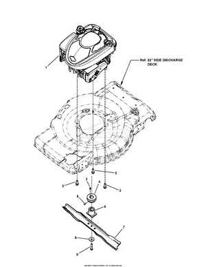
The connection between the cutting mechanism and the engine is crucial for the effective operation of lawn maintenance equipment. This component assembly not only facilitates the rotation of the blade but also contributes to the overall stability and efficiency of the machine. Understanding the design and functionality of these elements helps in maintaining optimal performance and prolonging the lifespan of the device.
Key Components of the Adapter
The adapter serves as the interface that secures the blade to the power unit. It typically features a robust construction to withstand the stresses generated during operation. Materials used in its fabrication often include durable metals, ensuring resistance to wear and tear. The design incorporates specific notches and holes that allow for proper alignment and attachment, promoting safe usage and efficiency.
Housing Structure Overview
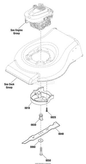
The housing structure encases the operational parts, providing protection and support. It is designed to absorb vibrations and impacts, thus enhancing the stability of the assembly during use. Adequate ventilation is also a consideration, as it helps to dissipate heat generated by the engine. A well-designed housing ensures that all components function harmoniously while minimizing the risk of damage from external elements.
Repair Tips for Common Issues
Addressing typical problems with small engines can enhance their performance and longevity. Understanding the root causes of frequent malfunctions allows for effective troubleshooting and maintenance, ensuring smooth operation. Below are some helpful insights for resolving common challenges faced by users.
Identifying Fuel-Related Problems
Fuel issues are a frequent cause of engine malfunctions. Stale fuel, improper mixing, or clogged filters can hinder performance. Always use fresh fuel and check for any blockages in the fuel lines. Regularly replacing fuel filters can also prevent potential complications.
Addressing Starting Difficulties
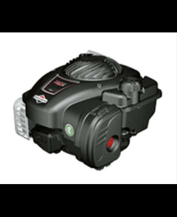
Starting problems may stem from several factors, including battery issues, spark plug wear, or air filter blockages. To enhance starting reliability, check the spark plug condition and replace it if necessary. Ensure that the air filter is clean and free from debris, allowing for optimal airflow.
Common Issues Possible Causes Suggested Solutions Engine Won’t Start Battery Failure, Clogged Air Filter Replace battery, clean or replace air filter Poor Engine Performance Stale Fuel, Dirty Spark Plug Use fresh fuel, replace spark plug Excessive Vibration Loose Components, Unbalanced Blades Tighten components, balance blades