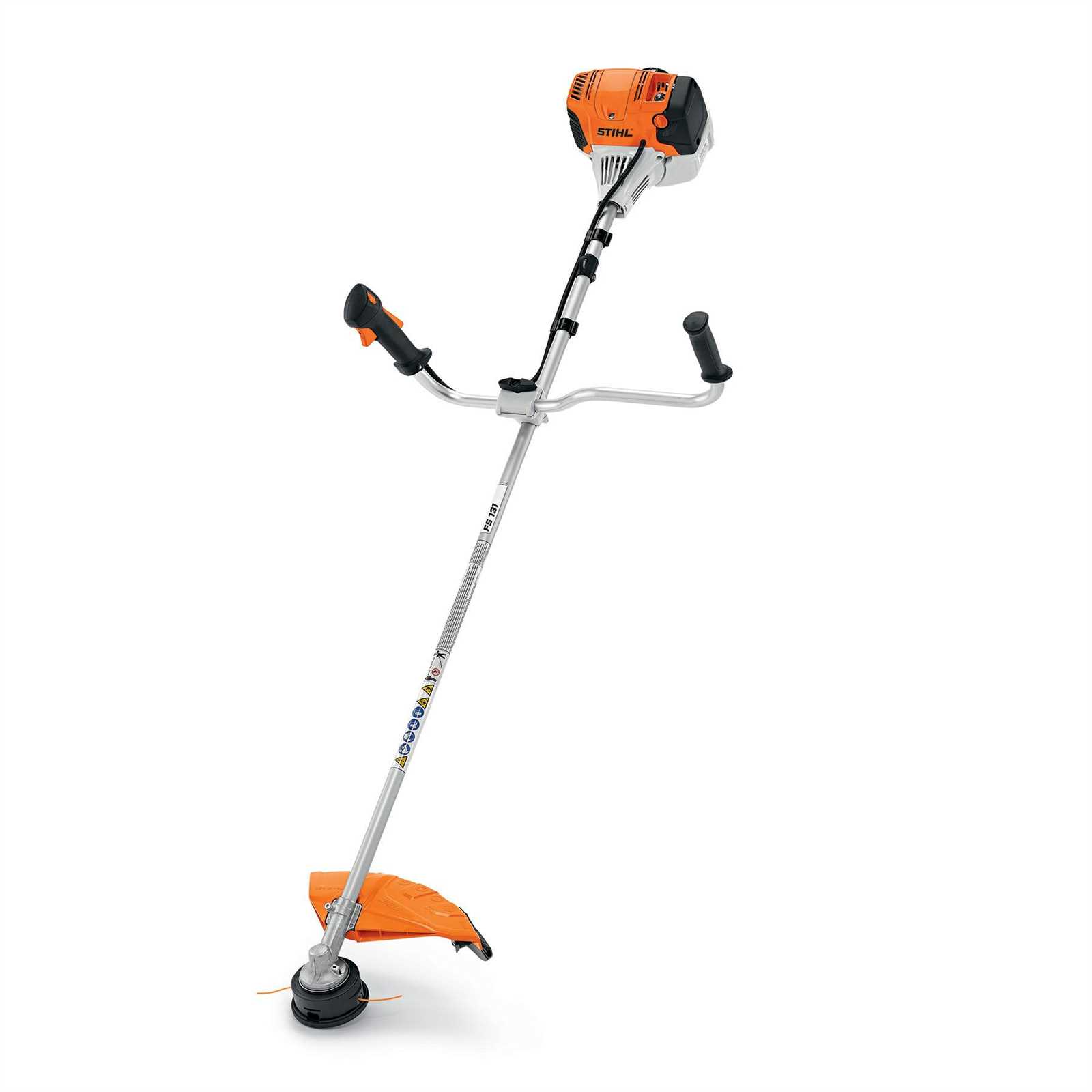
Stops the engine by grounding the ignition system, cut
Air Filter Assembly Guide
The air filter is a crucial component for ensuring the efficient operation of many devices, as it prevents dust and debris from entering the engine. Keeping this part in good condition can extend the lifespan of the machine and improve performance. In this guide, we’ll go over the basic steps involved in assembling the air filter.
- Start by locating the filter housing and ensure that the cover is securely fastened.
- Carefully remove the housing cover, paying attention to any clips or screws that may hold it in place.
- Take out the old air filter and inspect the filter area for dirt or damage.
- If necessary, clean the area around the filter to avoid contamination during reassembly.
- Insert the new or cleaned air filter, making sure it sits correctly in its slot.
- Replace the housing cover and secure it tightly.
Regular maintenance of the air filter helps to ensure smooth operation and protects the engine from harmful particles. It’s recommended to check and clean or repla
Throttle Mechanism and Maintenance
The throttle mechanism is a crucial component of any outdoor power equipment, responsible for controlling the engine speed and power output. Proper understanding and maintenance of this mechanism ensure optimal performance and longevity of the equipment. Regular checks and adjustments can help prevent issues and enhance efficiency.
Components of the Throttle Mechanism
The throttle mechanism consists of several key parts that work together to regulate engine speed:
- Throttle cable
- Throttle lever
- Spring assembly
- Carburetor linkage
Maintenance Tips
To ensure the smooth operation of the throttle mechanism, follow these maintenance tips:
- Inspect the throttle cable: Regularly check for wear or fraying. Replace if necessary.
- Clean the components: Remove dirt and debris from the throttle lever and linkage to ensure smooth operation.
- Check spring tension: Ensure that the spring is in good condition and properly tensioned to avoid sticking.
- Adjust the throttle linkage: Make sure the linkage is correctly adjusted for accurate throttle response.
Exploring the Cutting Head Structure
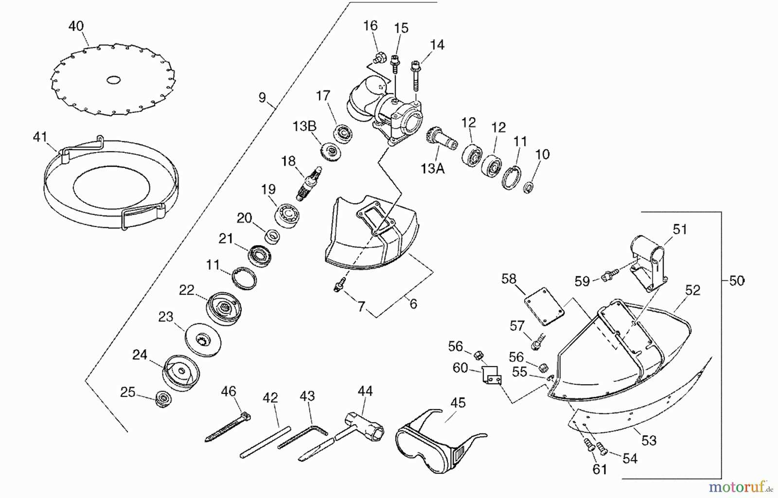
The cutting head serves as a pivotal component in the functionality of a grass trimming device. Its design significantly impacts the efficiency and precision of the tool, enabling users to achieve optimal results during various landscaping tasks. Understanding the structure of the cutting head can enhance one’s ability to maintain and operate the device effectively.
Main Components of the Cutting Head
- Cutting Line: The primary element responsible for trimming grass and vegetation.
- Spool: Houses the cutting line and allows for automatic line feeding.
- Cover: Protects the internal components and provides access for line replacement.
- Attachment Points: Designed to connect with the main shaft of the device.
Functionality of Each Component
- Cutting Line: The length and thickness of the line can vary, affecting the cutting performance based on the type of vegetation being trimmed.
- Spool: It is crucial for the smooth dispensing of the cutting line, ensuring that the user can maintain continuous operation without interruptions.
- Cover: Facilitates easy access to the spool for quick line changes, minimizing downtime during use.
- Attachment Points: Ensure a secure fit with the power head, allowing for optimal power transfer and control.
Handle and Control Setup
Proper assembly and adjustment of the handle and control mechanisms are crucial for achieving optimal performance and user comfort. A well-configured setup enhances maneuverability and ensures safe operation during usage.
To achieve an effective configuration, follow these steps:
- Begin by attaching the handle securely to the device, ensuring it is positioned at a comfortable height for the operator.
- Adjust the angle of the handle to promote ergonomic use, minimizing strain on the wrists and arms during operation.
- Connect the control elements, ensuring that they are easily accessible and functional, allowing for quick response during use.
- Test the configuration by performing a few operational checks to confirm that all components are functioning correctly and comfortably within reach.
Additionally, it is essential to regularly inspect the handle and control setup for wear or damage, as this will help maintain safety and efficiency during operation.
Shaft and Transmission Components
The shaft and transmission system plays a crucial role in the operation of a power tool, ensuring efficient power transfer from the engine to the working attachments. Understanding these components is essential for maintenance and troubleshooting, as they directly influence the tool’s performance and reliability.
Functionality Overview

The shaft is designed to transmit rotational force, while the transmission system converts this force into usable power for various attachments. This mechanism is vital for achieving optimal cutting efficiency and maneuverability during operation.
Key Components
| Component |
Description |
| Drive Shaft |
Connects the engine to the working attachment, facilitating power transfer. |
| Gearbox |
Adjusts the rotational speed and torque to match the requirements of the attachment. |
| Clutch |
Engages and disengages the power flow, allowing for better control during operation. |
| Bearings |
Support the shaft, reducing friction and wear during operation. |
Clutch System and Operation
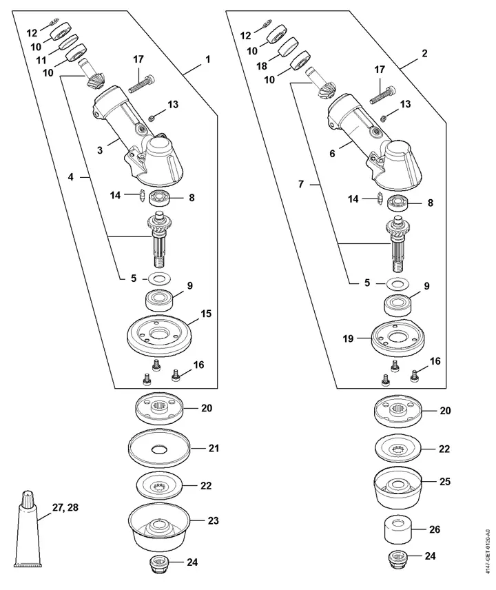
The clutch system is a crucial component in the functionality of various power equipment, enabling effective power transmission from the engine to the cutting tool. This mechanism is designed to engage and disengage power flow, ensuring smooth operation during use and preventing potential damage to the machine.
Components of the Clutch System
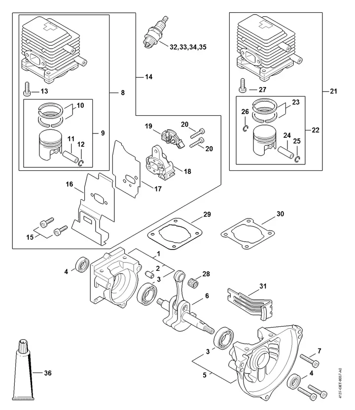
- Clutch Drum: The central part that houses the clutch shoes and connects to the engine’s output shaft.
- Clutch Shoes: These are spring-loaded components that expand against the clutch drum to engage the power transfer.
- Springs: Vital for the operation of the clutch shoes, controlling their engagement and disengagement based on engine speed.
- Driving Pin: This pin connects the clutch system to the cutting attachment, facilitating power delivery.
Operation of the Clutch System
The operation of the clutch system is primarily driven by the engine’s rotational speed. As the engine accelerates, centrifugal force acts on the clutch shoes, causing them to expand and make contact with the drum. This engagement allows power to flow to the cutting tool, enabling it to operate effectively. Conversely, when the engine speed decreases, the shoes retract due to spring tension, disengaging the power flow and allowing for idle operation. This system not only enhances performance but also ensures safety by preventing unintended engagement during startup.
Protective Guard and Safety Features
The protective mechanisms incorporated in cutting equipment play a crucial role in ensuring the safety of users. These features are designed to minimize the risk of accidents and injuries during operation, providing peace of mind while handling powerful machinery.
A well-designed shield is essential for preventing debris and hazardous materials from striking the operator. It acts as a barrier, ensuring that the user is shielded from potential flying objects that may occur during the cutting process. Additionally, safety interlocks are often included to prevent accidental starts, further enhancing the operational security of the equipment.
Moreover, ergonomic handles and grips contribute significantly to user safety by promoting a secure and comfortable hold. This reduces the likelihood of slipping, allowing for better control and precision during operation. Overall, these protective features are vital for maintaining a safe working environment and enhancing the overall user experience.
Replacing the Drive Shaft Parts
Ensuring the proper functioning of the drive mechanism is crucial for optimal performance. Over time, components within this system may wear out or become damaged, necessitating their replacement. Understanding how to effectively replace these elements can enhance the longevity of the equipment.
To begin the replacement process, gather the necessary tools and materials:
- Replacement components for the drive mechanism
- Wrench set
- Screwdriver set
- Grease for lubrication
- Safety gloves
Follow these steps for a successful replacement:
- Ensure the equipment is turned off and disconnected from any power source.
- Carefully remove the protective casing to access the drive mechanism.
- Identify the components that require replacement.
- Using the appropriate tools, detach the old components from the assembly.
- Install the new parts, ensuring a secure fit and proper alignment.
- Reapply any necessary lubrication to ensure smooth operation.
- Reassemble the protective casing, ensuring all screws are tightly secured.
Regular maintenance and timely replacement of these elements will contribute to the overall efficiency and reliability of the equipment.
|
