stihl fs 40 parts diagram pdf

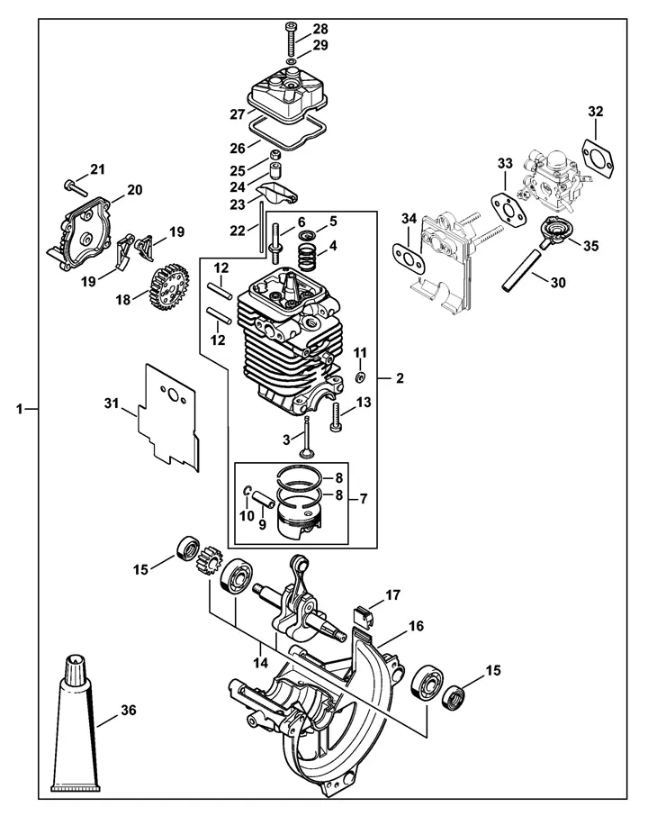
Delving into the inner workings of the FS 40 unveils a complex interplay of components and mechanisms designed to deliver reliable performance. Understanding the intricacies beneath the surface involves deciphering the assembly of essential parts that contribute to its functionality.

This examination goes beyond mere structure; it involves uncovering the integration of elements that drive the tool’s operational capabilities. Each segment plays a crucial role in ensuring efficiency and durability, reflecting meticulous engineering principles.

Peering into this intricate framework reveals the synergy between different parts, highlighting their collective contribution to the tool’s overall reliability and longevity.

Understanding Key Components of Stihl FS 40

In this section, we delve into the fundamental elements that make up the functionality of the Stihl FS 40, focusing on its essential components and their roles within the system. Exploring the integral parts that contribute to its operation, we uncover the intricacies of how each element interacts to ensure optimal performance and durability.

Engine Assembly Breakdown and Functions

The internal structure of the engine comprises several interconnected components that work in harmony to deliver power efficiently. Each element has its own role, contributing to the overall operation and ensuring smooth functionality. Understanding the layout and purpose of these components is essential for maintaining optimal performance and preventing issues during use.

Main Mechanical Components

At the heart of the system, the cylinder and piston form the core, converting fuel energy into mechanical motion. The crankshaft transfers this motion, driving other elements responsible for operation. Together, these parts ensure consistent energy output for extended operation. Regular inspection of these key elements helps in maintaining their efficiency over time.

Supporting Elements

The system also includes supporting components like gaskets, seals, and valves, which ensure that pressure is maintained, and no leaks affect performance. These parts play a vital role in balancing pressure and enabling the engine to function seamlessly. Ensuring that these smaller components are intact prevents unnecessary wear and tear on the larger elements.

Fuel System Overview and Maintenance Tips

The fuel system plays a crucial role in ensuring efficient operation and long-term reliability. It involves several components working together to deliver the necessary mixture for optimal engine performance. Keeping this system in good condition is essential for smooth functionality and minimizing potential issues.

Regular inspection of the fuel lines, filters, and connections can help prevent blockages or leaks, which could lead to reduced efficiency. Checking for cracks or wear in the tubing is important, as even small damage can disrupt fuel flow.

Maintaining a clean fuel filter ensures that contaminants don’t enter the engine, preserving its life and performance. Replacing the filter periodically according to manufacturer recommendations can prevent dirt buildup. Additionally, keeping the fuel tank free of sediment will contribute to a more stable fuel flow.

It’s essential to use the correct fuel mixture, as improper blending can cause issues such as engine stalling or poor combustion. Ensuring proper fuel storage, away from extreme temperatures, helps maintain its quality over time.

Fuel Line and Carburetor Parts Explained

The operation of small engines relies heavily on the correct flow and mixing of fuel and air. Key components ensure that fuel is efficiently delivered and that the right balance is achieved to maintain performance and reliability. In this section, we explore the vital elements responsible for managing this process, with a focus on the connectors and mechanisms involved in ensuring smooth engine operation.

Component Function
Fuel Line Transfers liquid from the reservoir to the central mixing area, ensuring a consistent supply during operation.
Carburetor Mixes liquid and air in precise proportions, regulating the engine’s power output and fuel efficiency.
Primer Bulb Facilitates starting by manually pumping fuel into the lines, bypassing potential air blockages in the system.
Gaskets and Seals Prevent leaks by ensuring a tight connection

Ignition System Parts and Their Roles

stihl fs 40 parts diagram pdf

The ignition mechanism in a power tool is a critical component that ensures smooth operation by creating the necessary spark to ignite the fuel-air mixture. Understanding the various elements involved in this process allows for better maintenance and troubleshooting, ensuring the machine remains reliable over time.

Spark plug: This small yet essential element is responsible for creating the initial spark needed for combustion. It transforms the electrical signal into a high-voltage arc that ignites the mixture in the combustion chamber.

Ignition coil: Acting as a transformer, the ignition coil boosts the low voltage from the tool’s electrical system into the high voltage required by the spark plug. Without this component, the spark wouldn’t be strong enough to start the engine.

Flywheel: The flywheel generates the magnetic field necessary to induce current in the ignition coil. Its proper functioning is essential to keep the spark consistent and timed correctly for the engine to run smoothly.

Maintaining these components and ensuring they function correctly is key to the overall performance of the machine’s ignition system.

Spark Plug and Ignition Module Insights

The ignition system in small outdoor equipment plays a crucial role in ensuring reliable operation. Understanding the relationship between key components like the spark generator and the electronic ignition unit is vital for maintaining peak performance. These elements work together to create the initial burst of energy required to start and run an engine efficiently.

Below is a summary of the core functions of the ignition components:

Component Function
Spark Generator Creates the necessary electrical arc to ignite the air-fuel mixture.
Ignition Unit Controls the timing and power of the ignition sequence for optimal engine function.
W

Cutting Mechanism and Blade Components

The efficient operation of any trimming equipment relies on its cutting system, which includes a variety of sharp-edged components designed to slice through grass and other vegetation. This system is engineered to balance durability with performance, ensuring smooth and precise cuts during use. Understanding how each element contributes to the overall functionality is essential for maintenance and repair.

Main Cutting Elements

The primary cutting tools include blades or strings that handle the actual trimming tasks. These elements are made from materials that provide strength while maintaining sharpness, allowing for clean cuts even in tougher environments. Regular inspection is necessary to prevent wear and maintain cutting efficiency.

Supporting Components

In addition to the main tools, there are various supporting elements that ensure the smooth operation of the system. These may include protective covers, fasteners, and balancing components. Each of these plays a crucial role in protecting both the user and the equipment, contributing to its overall longevity and safety during operation.

Trimmer Head and Line Replacement Guide

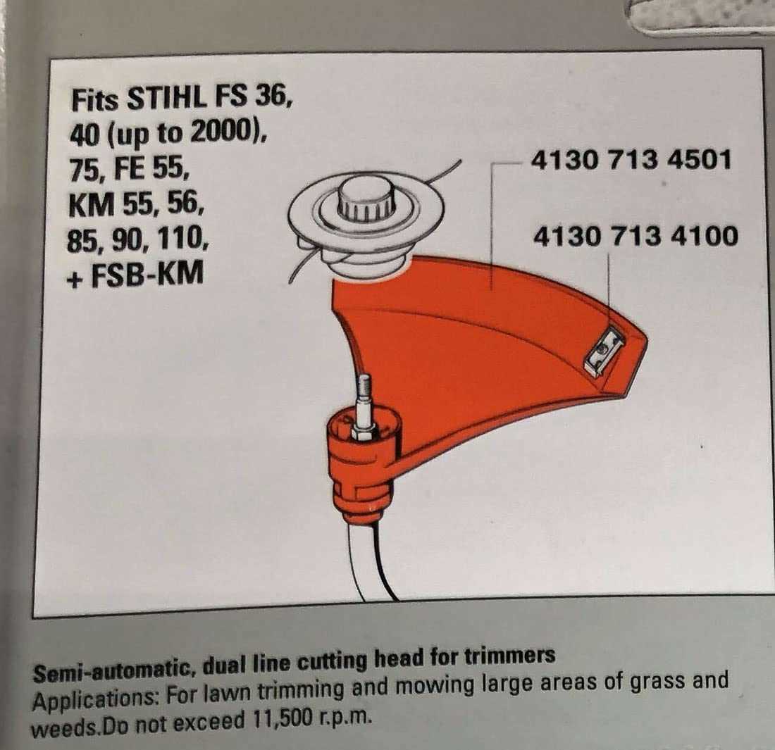
Maintaining an efficient cutting tool involves periodically changing the trimming head and line. This process not only ensures optimal performance but also enhances the longevity of your equipment. This guide provides a step-by-step approach to effectively replacing these essential components.

Before starting the replacement process, gather the necessary tools and materials:

  • New trimming head
  • Replacement line
  • Screwdriver
  • Safety gloves
  • Safety glasses

Follow these steps to successfully replace the trimming head and line:

  1. Ensure Safety: Before handling any components, disconnect the tool from the power source to prevent accidental starting.
  2. Remove the Existing Head: Use a screwdriver to unscrew the current trimming head. Carefully detach it from the main unit.
  3. Prepare the New Head: Take the new trimming head and prepare it for installation, ensuring all components are intact and ready for use.
  4. Install the New Head: Align the new head with the mounting point and secure it tightly using the screwdriver.
  5. Cut the Replacement Line: Measure and cut the replacement line to the recommended length, typically between 10-20 feet.
  6. Load the Line: Insert the new line into the head according to the manufacturer’s instructions, ensuring it is properly threaded.
  7. Final Checks: Ensure all components are securely fastened and that the line is correctly positioned for optimal cutting performance.

Regularly checking and replacing the trimming head and line can significantly improve the efficiency of your equipment. Following these steps will help ensure your tool remains in top condition for all your trimming tasks.

Handle and Throttle Controls Overview

The manipulation of controls plays a crucial role in the efficient operation of outdoor power equipment. Understanding how to properly interact with the handle and throttle mechanisms can significantly enhance user experience and performance. This section provides insights into the functionality and importance of these components in ensuring optimal operation.

Throttle Mechanism Functionality

The throttle mechanism regulates the power output of the equipment, allowing users to adjust the speed based on the task at hand. This adjustment is essential for maximizing efficiency and achieving desired results. A well-functioning throttle ensures a seamless transition between different operating speeds, enabling users to adapt to varying demands effectively.

Handle Design and Ergonomics

The design of the handle is critical for comfort and control during operation. Ergonomic considerations enhance grip and reduce fatigue, making prolonged use more manageable. Proper positioning and grip on the handle facilitate precise control, contributing to overall safety and efficiency.

Component Description Function
Throttle Lever Control for adjusting power output Regulates engine speed
Handle Grip Ergonomically designed for comfort Enhances control and reduces fatigue
Safety Lock Prevents accidental throttle engagement Ensures safe operation

Throttle Trigger and Safety Lock Assembly

The throttle trigger and safety lock mechanism play a crucial role in the functionality and safety of handheld equipment. This assembly ensures that the operator can easily control the device’s power output while minimizing the risk of accidental activation. Understanding the components and their interactions is essential for effective maintenance and operation.

Key components of this assembly include:

  • Throttle Trigger: This component allows the user to adjust the engine’s speed by controlling the flow of fuel and air. It is typically ergonomically designed for ease of use.
  • Safety Lock: The safety lock serves as a preventative feature, ensuring that the throttle trigger cannot be engaged unintentionally. This is especially important when the equipment is not in active use.
  • Linkage Mechanism: This connects the throttle trigger to the engine’s control system, translating the user’s input into actions that regulate engine performance.

Proper inspection and maintenance of the throttle trigger and safety lock are vital for optimal performance. Regular checks can help identify wear and tear, ensuring the equipment remains reliable and safe to operate.

  1. Check for smooth operation of the throttle trigger.
  2. Ensure the safety lock engages and disengages properly.
  3. Inspect for any visible damage or wear on the components.

By keeping these elements in good working order, users can enhance both the efficiency and safety of their equipment during operation.

Understanding the Air Filter and Housing

The air intake system is crucial for the optimal performance of any outdoor equipment. It plays a significant role in ensuring that the engine receives a clean supply of air necessary for efficient combustion. This section delves into the components involved, focusing on their functions and importance within the overall assembly.

Function of the Air Filter

The primary function of the air filter is to prevent dirt, debris, and other contaminants from entering the engine. A clean air supply is essential for maintaining engine efficiency and longevity. Regular maintenance of the air filter helps to ensure that the equipment operates smoothly, reducing the risk of engine damage.

Importance of the Housing

stihl fs 40 parts diagram pdf

The housing serves as the protective casing for the air filter. It is designed to securely hold the filter in place while allowing for proper airflow. Additionally, a well-constructed housing minimizes the entry of unwanted particles and supports the overall durability of the engine components. Proper sealing and installation of the housing are vital for maintaining optimal air intake conditions.

Proper Cleaning and Replacement Techniques

stihl fs 40 parts diagram pdf

Maintaining equipment in optimal condition is essential for ensuring longevity and performance. Regular cleaning and timely substitution of worn components can significantly enhance the functionality of your tool. This section outlines effective methods for cleaning various parts and guidelines for replacing them when necessary.

Cleaning Procedures

To keep your device functioning smoothly, regular cleaning is crucial. Begin by disconnecting the equipment from its power source. Use a soft brush or cloth to remove dirt and debris from accessible areas. For more stubborn grime, a mild detergent mixed with water can be applied. Always ensure that no liquid seeps into sensitive components. After cleaning, allow all parts to dry completely before reassembling.

Replacement Guidelines

Knowing when to replace components is as vital as keeping them clean. Inspect parts regularly for signs of wear, such as cracks or significant corrosion. When it’s time for a replacement, ensure you use compatible items that match the specifications of the original components. Follow the manufacturer’s guidelines for installation to avoid issues and ensure proper functionality. Keeping a record of replacement schedules can also help in maintaining the overall efficiency of the equipment.

Exploring the Drive Shaft and Gearbox

The drive shaft and gearbox are crucial components that facilitate the transfer of power within mechanical systems. Understanding their functionality and design is essential for effective maintenance and troubleshooting. These elements work in tandem to convert rotational motion into the necessary force required for operation, making them vital in various applications.

The drive shaft is responsible for transmitting torque from the engine to the working elements. Its design must accommodate significant stress and strain while ensuring efficient power transfer. The gearbox, on the other hand, serves to modify the speed and torque of the rotational motion. By selecting the appropriate gear ratios, the system can optimize performance for different tasks.

Component Function Key Features
Drive Shaft Transmits power from the engine Durable construction, lightweight materials
Gearbox Adjusts speed and torque Variable gear ratios, robust design

Regular inspection and maintenance of the drive shaft and gearbox are essential to prevent failures. Ensuring that these components are free from wear and damage will significantly enhance the longevity and reliability of the entire system. Understanding their roles and maintaining their integrity will lead to improved performance in all operations.