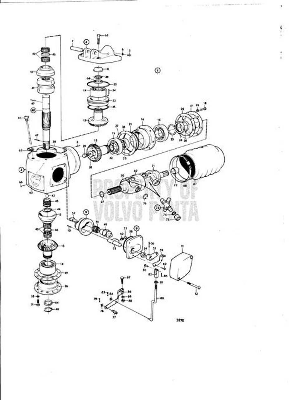
Understanding the structure and function of various mechanical systems is essential for efficient operation and maintenance. In this section, we will explore the arrangement of vital elements in a propulsion setup, emphasizing their interconnectivity and roles in ensuring smooth performance. Each component plays a critical role in the overall operation, and by examining their layout, one can gain insights into both the engineering design and functionality.
Our focus will be on the precise organization of various mechanical assemblies, providing a clear view of how different parts interact. This analysis will help in identifying crucial elements, understanding their purpose, and enabling accurate maintenance or replacement decisions. Whether you are troubleshooting or performing routine upkeep, having a detailed view of these components is invaluable for achieving long-term efficiency.
Understanding the Volvo Penta SX-M Structure
The intricate construction of this propulsion system offers a combination of performance, reliability, and efficient power transfer. By examining its key components and their interaction, one can gain insights into how the system achieves its optimal balance between control and propulsion. This section delves into the major elements of the structure and their specific functions, providing a clear overview of its design and operational principles.
Main Components and Their Functions
- Drive Unit: The core element responsible for converting engine power into effective thrust, ensuring smooth operation in various water conditions.
- Gear Housing: A critical enclosure that houses the transmission system, designed to protect moving parts from external elements while facilitating efficient gear shifts.
- Propeller Assembly: Directs the thrust generated by the engine, allowing for precise maneuvering
Key Components of the Drive Assembly
The propulsion system relies on an intricate arrangement of mechanical elements that ensure optimal performance and longevity. These interconnected parts work together to transfer power efficiently, enabling the smooth movement of the vessel through the water. Understanding the main elements in this assembly is crucial for maintenance and repair efforts, as each component plays a vital role in the system’s functionality.
Propulsion Unit
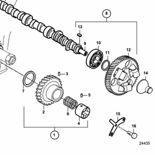
This section includes the mechanical setup responsible for converting engine output into thrust. It is designed to withstand harsh marine conditions, ensuring the vessel maintains speed and direction. Proper upkeep of this unit is essential to avoid disruptions in operation.
Steering Mechanism
The steering system provides precise control over the vessel’s movement. It ensures seamless maneuverability and quick response to directional changes.
Exploring the Exhaust System Configuration
The exhaust system is a vital component of any marine propulsion setup, ensuring the proper expulsion of gases and maintaining engine efficiency. Its configuration significantly impacts the performance, longevity, and environmental compliance of the engine. This section delves into the structural design, flow mechanisms, and the role of each element involved in guiding exhaust gases away from the engine.
Key Components Overview
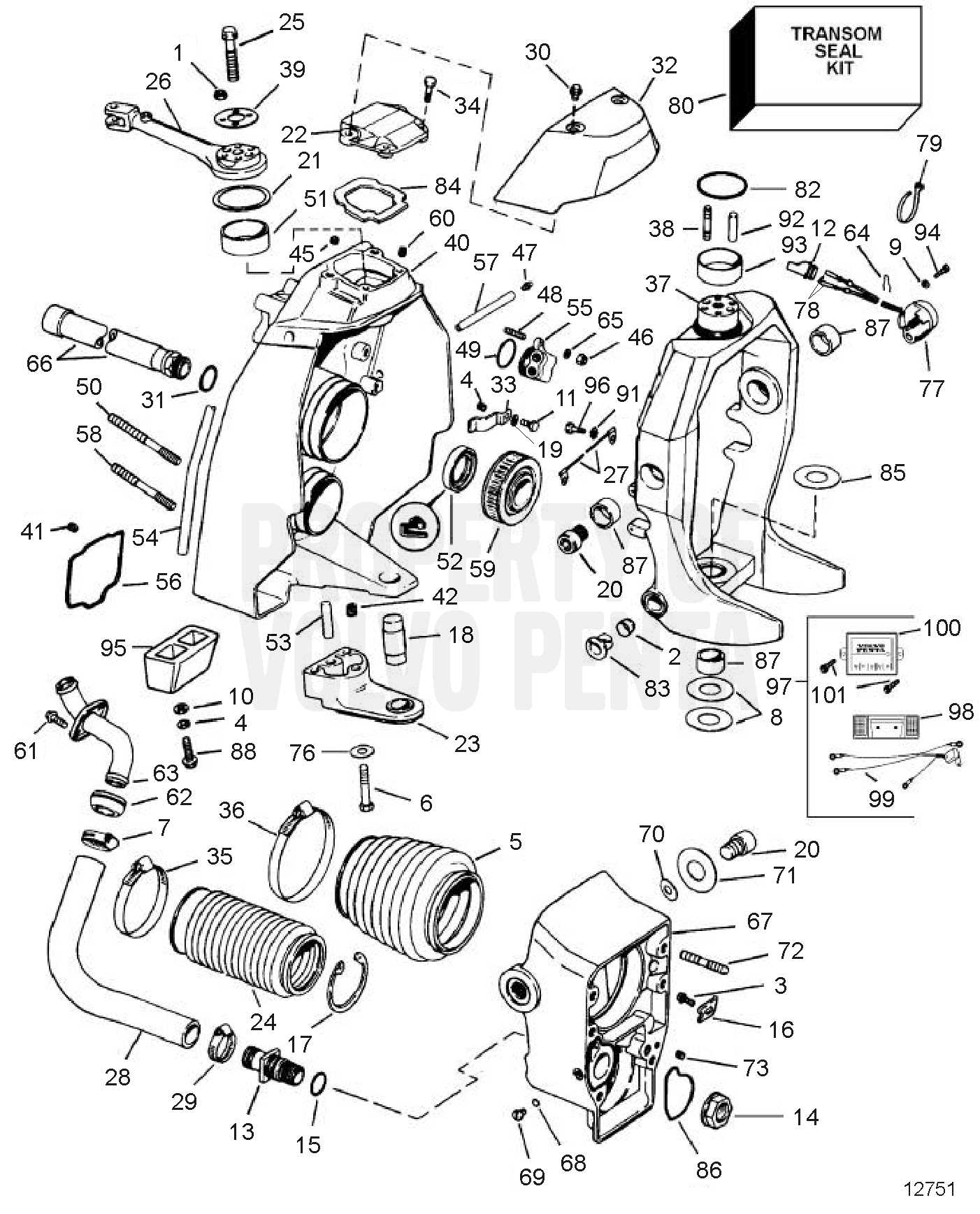
- Manifolds: These serve as the initial collection points for gases exiting the engine, directing them toward the next stages.
- Elbows: Curved connectors that channel gases downward or outward, preventing water ingress into the engine.
- Hoses: Flexible connectors that guide the exhaust to the outlet, ensuring a secure and leak-free path.
- Mufflers: Devices that reduce noise and smooth out the flow of gases, enhancing overall operational comfort.
Exhaust Flow Mechanism
The flow of exhaust gases starts from the engine, passes through the manifolds, and is then guided via the elbows to the water-cooled exhaust hoses. Each stage plays a role in optimizing both temperature control and emissions reduction. A well-configured exhaust setup
Functions of the Steering Mechanism
The steering system plays a crucial role in maintaining control and direction during movement on water. It is designed to provide seamless maneuverability, ensuring that the vessel responds accurately to the operator’s inputs. Understanding how each component works together can help ensure smooth navigation and safety in various conditions.
Core Responsibilities
- Directing the motion by transmitting input from the helm to the rudder or drive unit.
- Ensuring stability during turns and adjustments.
- Providing feedback to the operator, allowing for precise corrections.
Key Components Involved
- The helm, responsible for initiating changes in direction.
- The linkage system, which transmits the rotational movement to the drive unit.
- Hydraulic or mechanical systems that assist in reducing the effort required for steering.
By understanding these core functions, the operator can maintain better control and enjoy safer,
Overview of Cooling System Components
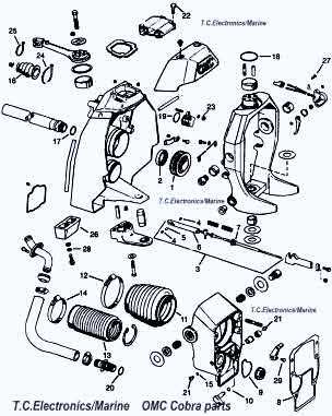
In every marine engine setup, maintaining a stable temperature is essential for optimal operation and long-term reliability. The cooling mechanism is designed to manage excess heat generated during combustion, ensuring the motor runs smoothly and efficiently. The key elements of this system work together to regulate temperature, prevent overheating, and support the overall performance of the engine.
Key Elements of the System
The core elements responsible for maintaining temperature balance include water pumps, hoses, and thermostats. Each of these components plays a unique role in directing coolant flow, allowing heat exchange, and maintaining proper temperature levels across various operating conditions.
Flow Path and Operation
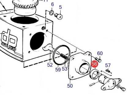
The cooling medium is circulated through different parts of the engine in a controlled manner. This flow ensures that areas most prone to heat build-up are adequately cooled. The system relies on a network of pumps and valves to manage the movement of the coolant, making sure the temperature remains stable.
Component Inspecting the Propeller Shaft Layout
Understanding the structure and alignment of the rotating assembly is crucial for ensuring optimal performance in marine applications. By thoroughly examining how each component is arranged and interacts with the others, you can identify potential issues that may affect the overall efficiency of the system. Regular checks and assessments of the rotating mechanism help in maintaining smooth operation and longevity.
The rotating assembly consists of several interconnected elements, each playing a vital role in transferring power effectively. Paying attention to how these parts are positioned and supported within the system is essential to prevent imbalances or misalignments that could lead to premature wear or damage. Proper maintenance and adjustments, when necessary, ensure smooth and reliable operation under varying conditions.
Trim and Tilt System Breakdown
The trim and tilt mechanism plays a crucial role in adjusting the angle and position of a marine propulsion system. This functionality enhances performance, allowing smoother navigation by raising or lowering the propulsion unit based on varying conditions. Understanding its components and how they interact ensures optimal handling, especially in challenging environments.
Core Components and Functions: The system typically consists of hydraulic elements, electric actuators, and mechanical linkages. These parts work together to modify the orientation of the propulsion unit, allowing for both vertical adjustments and fine-tuning of the angle. This helps in controlling the vessel’s movement through various water conditions.
Operational Considerations: Proper maintenance and regular inspections of this system are essential to prevent malfunction. Keeping the hydraulic fluids at proper levels and ensuring the actuators
Clutch and Gear Mechanism Overview
The intricate system of components responsible for transmitting power and controlling motion within a marine propulsion setup requires a detailed understanding of its core functions. This section outlines the essential interaction between the clutch and gear mechanism, focusing on their roles in enabling smooth transitions and efficient operation under varying conditions. With a focus on precision and durability, these elements are key to maintaining reliable functionality.
Component Function Clutch Assembly Engages and disengages power to the drive system, allowing control over propulsion. Gear Set Transfers rotational motion while adjusting the torque and speed of the system. Shift Mechanism Fuel System Parts and Connections
The fuel system is a critical component in ensuring optimal engine performance. It comprises various elements that work together to deliver fuel efficiently from the tank to the engine. Understanding the layout and relationships between these components is essential for effective maintenance and troubleshooting.
Key Components of the Fuel System
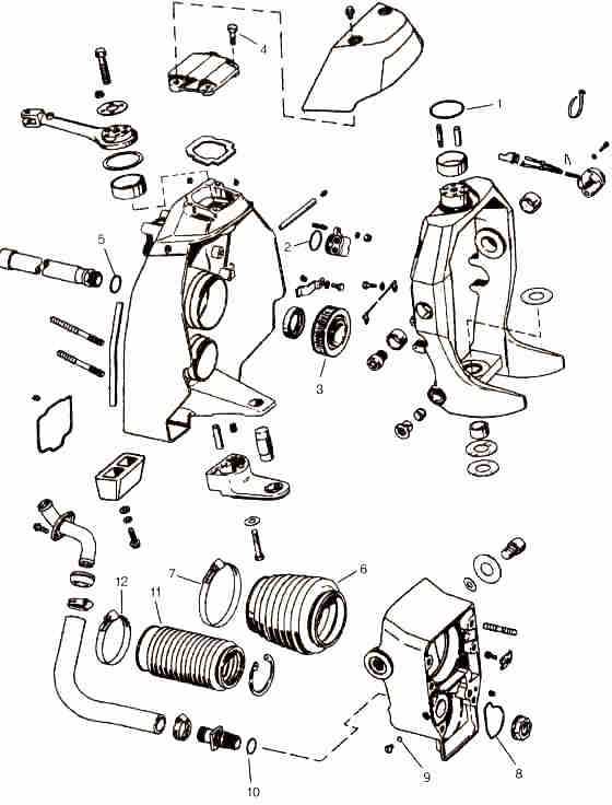
Each element within the fuel mechanism serves a specific purpose, contributing to the overall functionality. The main components typically include fuel pumps, filters, injectors, and hoses. Each part plays a vital role in regulating fuel flow, maintaining pressure, and ensuring that the engine receives the right amount of fuel at the right time.
Connections and Flow Path
Proper connections between these components are crucial for seamless operation. Any obstruction or failure in the connections can lead to fuel delivery issues, affecting engine performance. Below is a summary of typical connections and their respective functions:
Component Function Fuel Pump Moves fuel from the tank to the engine. Fuel Filter Removes impurities and contaminants from the fuel. Fuel Injectors Injects the appropriate amount of fuel into the engine’s combustion chamber. Hoses Transport fuel between components while maintaining pressure. Hydraulic System Component Layout
The hydraulic system plays a crucial role in the overall functionality of marine propulsion systems. Understanding the arrangement of its components is essential for effective maintenance and troubleshooting. This section outlines the key elements within the hydraulic framework and their interconnections, which contribute to the seamless operation of the vessel.
Main Components
- Hydraulic Pump: Converts mechanical energy into hydraulic energy, providing necessary pressure.
- Hydraulic Reservoir: Stores hydraulic fluid, ensuring a steady supply to the system.
- Actuators: Facilitate the movement of various parts by converting hydraulic pressure into mechanical motion.
- Valves: Control the flow and direction of hydraulic fluid, allowing for precise manipulation of the system.
- Hoses and Fittings: Transport hydraulic fluid between components, maintaining system integrity.
System Flow Overview
The flow of hydraulic fluid is pivotal in ensuring efficient operation. The following sequence outlines the typical flow path within the hydraulic circuit:
- Fluid is drawn from the reservoir by the hydraulic pump.
- The pump pressurizes the fluid and directs it to the valves.
- Valves regulate the flow to actuators, initiating movement.
- Fluid returns to the reservoir after passing through the actuators, completing the cycle.
Electrical Connections and Wiring Diagram
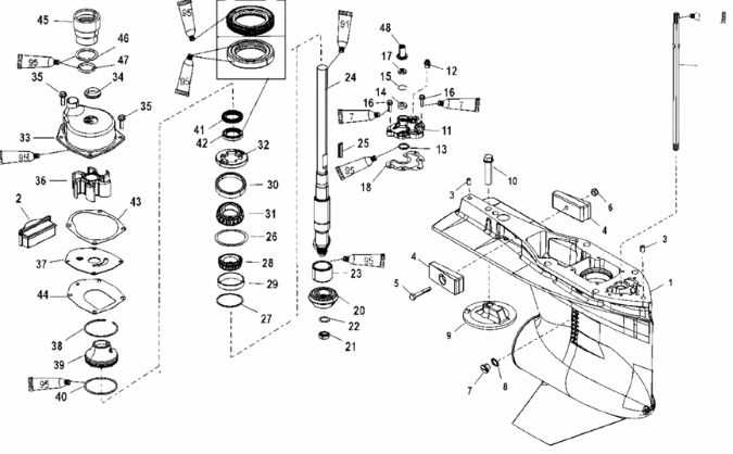
This section provides an overview of the electrical interfaces and wiring configurations essential for the smooth operation of marine propulsion systems. Understanding these connections is crucial for ensuring that all components communicate effectively and function reliably in various operating conditions.
Overview of Electrical Interfaces
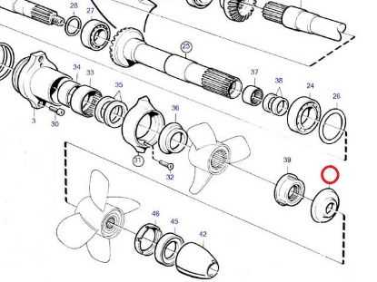
Proper integration of electrical systems involves recognizing the roles of each connection point. These interfaces facilitate communication between different elements, such as sensors, actuators, and control units. An accurate understanding of these interactions can help in troubleshooting and enhancing overall performance.
Wiring Configurations
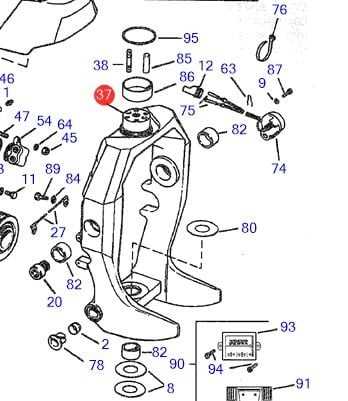
The wiring layout typically consists of color-coded cables that indicate specific functions. It is vital to adhere to standard practices when connecting these wires, as incorrect configurations can lead to system failures. For instance, power cables should be adequately insulated and secured to prevent short circuits, while signal wires must be routed away from sources of interference to maintain signal integrity.
Emphasis on Safety: Always prioritize safety during installation and maintenance. Ensure all connections are tight, and use protective equipment when working with electrical systems.
Maintenance Tips for Key Parts
Proper upkeep of essential components is vital for ensuring the longevity and efficiency of your marine engine system. Regular attention to these elements can prevent costly repairs and enhance overall performance. Here are some practical suggestions for maintaining critical elements of your watercraft.
Regular Inspections
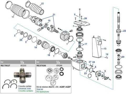
Conducting frequent examinations is crucial for identifying wear and tear early. Look for signs of corrosion, cracks, or unusual wear on the following components:
- Drive unit seals
- Propeller and its components
- Trim cylinders
- Exhaust system
Lubrication and Cleaning
Keeping moving parts well-lubricated and clean will significantly improve functionality. Consider the following practices:
- Use high-quality lubricant for gear systems and joints.
- Regularly clean away salt and debris from all surfaces.
- Check and replace grease in bearings as needed.
By adhering to these maintenance practices, you can enhance the reliability and performance of your engine components, ensuring a smoother and more enjoyable experience on the water.
Identifying Common Wear and Tear Areas
Understanding the areas prone to deterioration in marine propulsion systems is crucial for maintaining optimal performance and longevity. By recognizing these key regions, operators can proactively address issues, ensuring reliability during operation.
Key Areas of Concern

- Propeller and Drive Shaft: Regular inspection of these components is essential, as they are exposed to harsh conditions and may suffer from pitting, corrosion, or misalignment.
- Seals and Gaskets: Over time, seals can degrade due to exposure to water and varying temperatures, leading to leaks that may affect performance.
- Transom Assembly: This area is susceptible to wear from constant movement and environmental exposure, which can result in structural weaknesses.
- Trim and Tilt Mechanism: Frequent use can lead to wear on hydraulic components, impacting the overall functionality of the system.
Maintenance Tips
- Conduct routine inspections and maintenance schedules to catch issues early.
- Replace worn components promptly to prevent further damage.
- Utilize quality materials for repairs to enhance durability.
- Stay informed about common issues specific to the system to facilitate timely interventions.