Marine engines are complex systems that rely on the smooth operation of many individual elements to function effectively. Whether for maintenance or upgrading, having a clear view of how these components work together is essential. By exploring the structure of these mechanical systems, you can better understand how to maintain and optimize them.
Maintenance and proper alignment of various elements within the system ensure the longevity and performance of marine engines. Knowing how these critical elements interact helps prevent potential issues, leading to smoother operations and enhanced reliability on the water.
When it comes to keeping your engine in top condition, paying attention to the details and regularly checking key components is vital. Each piece plays an important role in the overall functionality, ensuring that your marine adventures are safe and enjoyable.
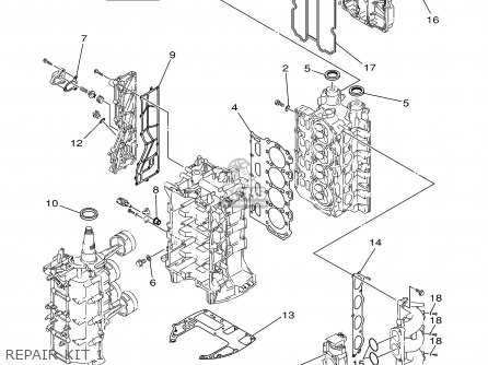
Yamaha F115 Engine Components Overview
The outboard motor in question features a variety of essential internal systems that ensure smooth operation and long-lasting performance. Each part plays a critical role in maintaining efficiency, reliability, and power output. Understanding the key elements involved provides a clearer picture of how these machines function and what makes them durable.
Key mechanical elements include the primary power generation unit, fluid systems for cooling and lubrication, and electrical components for ignition and control. These components work in unison to offer both high efficiency and adaptability, regardless of conditions.
Additionally, the layout of these systems is designed to facilitate maintenance and reduce downtime, allowing for easier access to critical parts during inspections or repairs. This ensures both professional users and recreational owners can keep their equipment in top condition with minimal hassle.
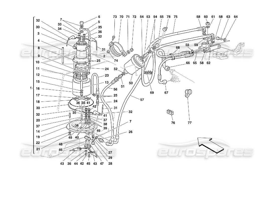
Understanding the Fuel System Layout
The fuel system is an essential component in ensuring the engine runs smoothly and efficiently. Its structure involves several interconnected elements that work together to deliver fuel from the tank to the engine in a controlled and optimized manner. Understanding how each component contributes to this process can help in maintaining and troubleshooting any potential issues.
Main Components of the Fuel System
The fuel system is made up of various parts that collaborate to provide a continuous and stable flow of fuel. Here are the key elements:
- Fuel tank: Stores the fuel before it’s delivered to the engine.
- Fuel pump: Transfers fuel from the tank to the engine at the required pressure.
- Fuel filter: Removes impurities to ensure clean fuel reaches the engine.
- Injec
Electrical Wiring and Connections Explained
Understanding the intricate nature of electrical wiring and connections is essential for ensuring the proper functioning of any motorized system. The layout of wires, combined with their precise connectivity, directly impacts both performance and safety. Well-organized wiring reduces the risk of short circuits and helps maintain efficiency across all electrical components.
Wire Types and Functions play a crucial role in transmitting power and signals. Different gauges and materials are chosen based on the load they need to carry, while insulation quality determines their durability and safety. Properly identifying the correct wiring ensures that the electrical flow is uninterrupted and reliable.
Connection methods such as crimping, soldering, and using connectors are vital for stable links between components. Each technique offers its advantages, but the ultimate goal is to achieve a secure and lasting bond that can withstand vibrations, heat, and environmental stress. Poor connections can lead to power loss or system failure, so precision is key.
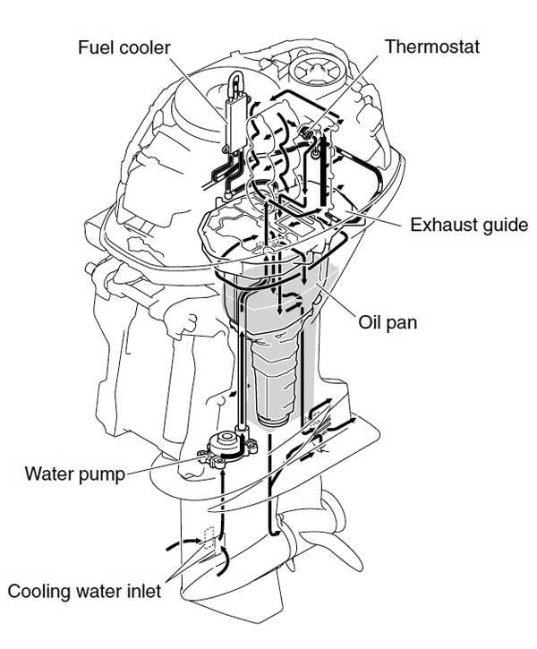
Detailed Breakdown of the Cooling System
The cooling system is designed to maintain optimal temperature levels during operation, ensuring the engine runs smoothly and efficiently. By regulating heat, it prevents overheating and contributes to the overall performance and longevity of the machinery.
Main Components of the Cooling Mechanism
The cooling mechanism consists of several key elements, each playing a crucial role in managing the engine’s temperature. These components work together to circulate coolant, drawing heat away from critical areas and dissipating it effectively.
How the Cooling Process Works
The process begins when the engine heats up. The coolant absorbs the excess heat and moves through various channels to the radiator, where the temperature is reduced. This continuous cycle ensures that the engine stays within a safe temperature range, preventing damage and ensuring reliability during prolonged use.
Throttle and Control Mechanisms Overview

In marine engines, throttle and control systems are crucial for ensuring smooth operation and maneuverability. These mechanisms help regulate the engine’s speed and response, providing the operator with full command over the vessel. Efficient control systems are essential for optimizing performance, ensuring safety, and providing a comfortable user experience.
Main Components of the Throttle System
The throttle system typically includes a lever, cables, and connecting elements. The lever is used to adjust the engine speed, while the cables transmit this motion to the engine. The precision and responsiveness of these components are vital for proper operation.
Importance of Control Mechanisms
Control mechanisms encompass more than just throttle management. They include steering, shifting gears, and various sensors. These components work together to ensure the vessel can be controlled with accuracy and ease, making it possible to navigate different water conditions.
Regular maintenance and timely inspections of
Key Components of the Exhaust System
The exhaust system of an outboard motor is crucial for controlling emissions and directing gases away from the engine. It ensures optimal performance by reducing noise and managing the release of hot gases, contributing to smoother operation and longevity of the engine. Understanding the key elements that make up this system can help in identifying potential issues and maintaining overall efficiency.
Components Involved in the Exhaust Flow
The exhaust system is comprised of several vital parts that work together to ensure proper gas expulsion and cooling. These components are designed to handle extreme conditions, including high temperatures and corrosive environments. Each part plays a role in maintaining engine power while keeping it environmentally friendly.
Exhaust Components Overview
Component Description Function Exhaust Manifold Directs exhaust gases from the engine’s cylinders. Ensures gases are expelled efficiently, minimizing engine strain. Water Cooled Exhaust A system that circulates water around the exhaust to cool the gases. Prevents overheating and reduces engine noise. Exhaust Pipe A channel that carries exhaust gases to the outlet. Transfers the gases from the engine to the exterior, minimizing backpressure. Exhaust Muffler Reduces the noise created by the engine. Minimizes sound pollution while maintaining exhaust efficiency. Exhaust Port The exit point where the gases leave the engine. Directs the gases safely away from the engine, preventing backflow. Ignition System Structure and Function
The ignition system in an outboard engine plays a vital role in ensuring efficient combustion by generating a spark at the right moment. It consists of several key components working together to initiate the process that powers the engine. Each part of this system contributes to the timely creation of electrical energy that is transformed into a spark, enabling the fuel-air mixture to ignite and produce power.
At the heart of this system is the coil, which stores and amplifies electrical energy from the battery. This energy is then released at the optimal time, creating a spark through the spark plug. The system is carefully designed to ensure that this ignition process happens reliably and consistently, providing smooth operation and maximum performance. Other components, such as the trigger and stator, help regulate the timing and strength of the spark, making the ignition system a crucial element in the overall function of the engine.
Oil Flow and Lubrication Diagram
The lubrication system is essential for maintaining optimal performance and longevity of an engine. It ensures that all moving parts receive proper oil distribution, reducing friction and wear. This system typically includes oil channels, pumps, and filters that work together to circulate the lubricant throughout the engine components.
A clear understanding of how oil circulates through the engine allows for better maintenance and troubleshooting. The process begins with oil being drawn from the sump, pumped through filters, and distributed to areas requiring lubrication, such as the crankshaft and camshaft. Once the oil has lubricated the components, it returns to the sump to be recirculated.
Gearbox Assembly and Components Guide

The gearbox is a critical element in any marine engine, responsible for transmitting power from the engine to the propeller. Understanding the assembly and key components is essential for proper maintenance and optimal performance. This guide outlines the different parts and how they work together to ensure smooth operation and longevity of the system.
Key Components of the Gearbox

The main components of the gearbox include the drive shaft, gears, and housing. These elements work in unison to manage the direction and speed of the vessel. The drive shaft connects the engine’s output to the gear system, while the gears control the speed and torque transferred to the propeller. The housing encloses and protects the internal components from water and debris.
Assembly Process
When assembling the gearbox, each component must be precisely aligned to avoid unnecessary wear and ensure efficient function. Proper lubrication is crucial for minimizing friction and preventing overheating. It’s important to follow the manufacturer’s specifications to guarantee that the system functions as designed and maintains durability over time.
Propeller Parts and Maintenance Tips
Ensuring the longevity and optimal performance of your boat’s propeller system requires regular inspection and upkeep. A well-maintained propeller not only enhances fuel efficiency but also ensures smoother navigation through water. Proper care involves understanding the key components that contribute to its function and taking proactive steps to avoid common wear and tear.
Key Components of a Propeller Assembly
The propeller assembly consists of several crucial elements, each playing a role in driving the vessel forward. These include the blades, hub, and shaft. The blades, often made of durable materials, are responsible for generating thrust. The hub connects the blades to the shaft, transferring the engine’s power efficiently. Regular checks of these components will help identify any signs of damage or corrosion.
Maintenance Tips for Longevity
Maintaining your propeller involves routine cleaning, inspection for cracks or dents, and ensuring proper alignment with the shaft. It is also recommended to inspect the blades for any debris or marine growth that may impede their efficiency. Lubricating the hub and keeping the shaft free from rust will help prevent premature wear, ensuring smooth and safe operation during your outings on the water.
Hydraulic System Overview
The hydraulic system in a marine engine plays a crucial role in ensuring smooth operation and efficient power transfer. It is responsible for controlling the movement of various components, such as the steering and trim systems, which are vital for the performance and maneuverability of the vessel. Understanding the key elements of this system helps in maintaining optimal functionality and addressing any potential issues that may arise over time.
Key Components of the Hydraulic System
- Pump: Responsible for generating hydraulic pressure that powers the system.
- Reservoir: Stores the hydraulic fluid necessary for smooth operation.
- Actuators: Convert hydraulic pressure into mechanical movement, controlling steering and trim angles.
- Hoses and Fittings: Transmit hydraulic fluid between components while ensuring a leak-free connection.
- Control Valves: Direct the flow of hydraulic fluid to specific areas within the system.
Maintenance Tips for the Hydraulic System
- Regularly check the hydraulic fluid level to ensure proper operation and prevent air from entering the system.
- Inspect hoses and fittings for wear, cracks, or leaks to maintain a secure and efficient hydraulic flow.
- Clean and replace the reservoir filter as needed to prevent contaminants from damaging the system.
- Test the pressure regularly to ensure the system operates within the manufacturer’s recommended range.
- Address any unusual noises or performance issues promptly to avoid further damage to the system.